3D Reconstruction of Occluded Luminous Objects
Akira Nagatsu, Fumihiko Sakaue and Jun Sato
Nagoya Institute of Technology, Nagoya 466-8555, Japan
Keywords:
NLOS, Occluded Objects, Luminous Object, 3D Reconstruction, GAN, Luminance Distribution.
Abstract:
In this paper, we propose a method for recovering the 3D shape and luminance distribution of an invisible
object such as a human around a corner. The human body is a heat-generating object, so it does not emit
visible light but emits far-infrared light. When a luminous object is around the corner, it cannot be observed
directly, but the light emitted by the luminous object reflects on the floor or wall and reaches the observer.
Since the luminous intensity of an object such as a human body surface is not uniform and unknown, its 3D
reconstruction is not easy. In this paper, we propose a method to recover an occluded luminous object with
non-uniform luminance distribution from changes in intensity patterns on the intermediate observation surface.
1 INTRODUCTION
Measuring the shape, location, and speed of an un-
seen object such as a human around the corner is very
important for avoiding accidents on the road. The re-
covery of information on occluded objects is called
NLOS (Non-Line of Sight), and research in this field
has advanced in recent years (Velten et al., 2012;
Chen et al., 2019).
However, the conventional NLOS methods re-
quire special measurement systems that scan and ir-
radiate the laser beam and also require prior mea-
surement of the reflectance of the observation surface,
such as a wall surface. Therefore, we in this paper
propose a new method for the 3D reconstruction of
occluded objects without using active light illumina-
tion and without knowing the reflectance of the obser-
vation surface.
Generally, in human recognition and reconstruc-
tion, the human body is treated as an object that does
not emit light. However, since the human body is
a heat-generating object, it emits far-infrared light.
Therefore, in the far-infrared region, the human body
can be considered a luminous object. In this paper,
we propose a method for recovering the 3D structure
of a luminous object such as a human body that exists
in an invisible position by using indirect light.
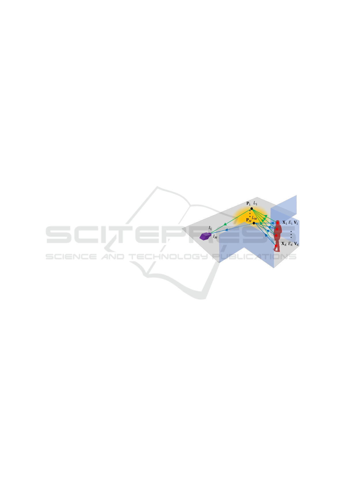
As shown in Fig. 1, the light emitted by the lumi-
nous object reflects on the floor or wall and reaches
the observer. Thus, the observer can observe the in-
direct light emitted by the luminous object. The lu-
minous intensity of a luminous object is in general
not uniform but varies from point to point. Thus,
Figure 1: Indirect observation of luminous objects.
we aim to realize 3D reconstruction of occluded lu-
minous objects with non-uniform luminance distribu-
tion. For this objective, we propose a method for re-
covering the luminance distribution E and 3D shape
X of the luminous object simultaneously from indirect
light observation images I. In this paper, we assume
that the camera is appropriately selected according to
the wavelength of light emitted from the luminous ob-
ject, and treat visible light and invisible light without
distinction.
2 RELATED WORK
The recovery of information on objects in occluded
locations is called NLOS (Non-Line of Sight) mea-
surement, and its research has been progressing in re-
cent years. In general, NLOS measurements are per-
formed by projecting a laser beam or other light onto
a wall and observing the reflected light coming back
990
Nagatsu, A., Sakaue, F. and Sato, J.
3D Reconstruction of Occluded Luminous Objects.
DOI: 10.5220/0011724800003417
In Proceedings of the 18th International Joint Conference on Computer Vision, Imaging and Computer Graphics Theory and Applications (VISIGRAPP 2023) - Volume 5: VISAPP, pages
990-996
ISBN: 978-989-758-634-7; ISSN: 2184-4321
Copyright
c
2023 by SCITEPRESS – Science and Technology Publications, Lda. Under CC license (CC BY-NC-ND 4.0)

from the object through the wall surface. (Velten et al.,
2012; Chen et al., 2019). For this reason, these NLOS
methods require complex optics and special observa-
tion systems that scan and measure the laser or beam
light at high speed.
In contrast, in recent years, Some methods for re-
covering an occluded scene only from images pas-
sively observed by a camera have been developed.
Most of these methods are based on placing some
shielding objects between the scene and the wall,
and using the half-shadow information produced by
the shielding objects (Bouman et al., 2017; Saunders
et al., 2019; Yedidia et al., 2019). However, these
methods can only recover 2D image information of
the scene, and cannot recover 3D shapes of objects
in the scene. A method for recovering the light field
in the scene has also been proposed. (Baradad et al.,
2018). However, this method can only recover 2D
images at multiple viewpoints and cannot recover 3D
objects in the scene which are the source of the light
field. In other words, this method cannot obtain the
correspondence of light rays in the light field.
On the other hand, there are some attempts to per-
form 3D measurements by passive NLOS observation
of luminous objects (Maeda et al., 2019; Kaga et al.,
2019). However, these are limited to the estimation of
a single light source or planar luminous objects with
uniform luminous intensity. No generalized method
for estimating the 3D shape of a luminous object and
its non-uniform luminance distribution has been con-
sidered so far.
Thus, we in this paper propose a method for recov-
ering 3D structure and non-uniform luminance distri-
bution of occluded luminous objects. We believe that
this is the first paper to tackle this difficult problem.
3 PROPOSED METHOD
3.1 Indirect Observation of Luminous
Objects
Suppose a luminous 3D object and a camera that ob-
serves it are separated from each other by a wall and
are positioned so that they cannot see each other as
shown in Fig. 1. The light emitted from the luminous
object is diffusely reflected at an intermediate obser-
vation surface such as a wall or floor, and the reflected
light is observed by the camera.
In this paper, the 3D shape of a luminous object
is represented by K 3D points X
k
= [X
k
, Y
k
, Z
k
]
⊤
(k =
1, ··· , K), and each of these 3D points has a different
luminous intensity E
k
(k = 1, ··· , K).
When the surface is illuminated by these K light
source points X
k
, the illuminance L
m
(m = 1, ··· , M)
at M points P
m
(m = 1, ··· , M) on the observed sur-
face can be described as follows:
L
m
=
K
∑
k=1
V
km
E
k
cosθ
km
∥X
k
− P
m
∥
2
(1)
where, θ
km
represents the angle between the surface
normal N
m
at point P
m
on the observation surface and
the direction of the light source X
k
. Assuming that the
observation surface is planar, θ
km
can be described by
using the surface normal N
m
as follows:
cosθ
km
=
(X
k
− P
m
) · N
m
∥X
k
− P
m
∥
(2)
V
km
represents the visibility, and it takes 1 if the
source point X
k
is visible from P
m
on the observation
surface, and takes 0 if it is invisible.
Suppose the reflectance of the point P
m
on the ob-
servation surface is ρ
m
, and the nonlinear intensity
response function of the camera is C. Then, the in-
tensity I
m
of point P
m
observed by the camera can be
described as follows:
I
m
= C[ρ
m
L
m
] (3)
In this paper, we assume that the response function C
can be obtained a priori and consider the normalized
intensity J
m
, in which the effect of C is removed as
follows:
J
m
= C
−1
[I
m
] = ρ
m
L
m
(4)
Unfortunately, it is not possible to obtain the 3D
structure of the light source X
k
(k = 1, ··· , K) from
the M intensity values J
m
(m = 1, · · · , M) in the im-
age. This is because there are a total of M + 4K un-
knowns (3K of the 3D point coordinates, K of their
luminances, and M of the reflectance of the observed
surface), while there are only M intensity informa-
tion obtained by observation. Therefore, no matter
how many observation points M are increased, the
3D points cannot be recovered. One way would be
to measure the reflectance of the observed surface in
advance, but this would severely hamper its applica-
tion to unknown scenes. Thus, in the next section,
we solve this problem by using observations at multi-
ple time instants assuming that the luminous object is
moving in the scene.
3.2 Recovering Occluded 3D Luminous
Objects
Suppose a 3D luminous point X
k
is moving in the 3D
space and its motion is V
k
= [V
Xk
, V
Y k
, V
Zk
]
⊤
. The 3D
3D Reconstruction of Occluded Luminous Objects
991
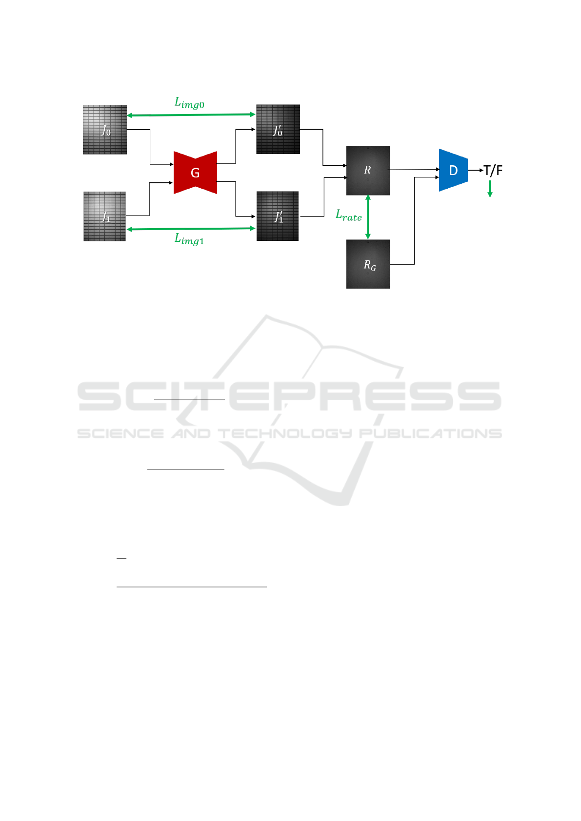
Figure 2: Network used in our method, which generates a pair of specular-free images from input camera images.
luminous object can be rigid or non-rigid, so the mo-
tion of the 3D luminous points can be different or the
same from point to point. Then, the luminous point
existing at X
k
at the current time exists at X
k
−tV
k
at
t time ago. Thus, the intensity J
t
m
observed at t time
ago can be described as follows:
J
t
m
= ρ
m
K
∑
k=1
V
km
E
k
cosθ
t
km
∥X
k
−tX
k
− P
m
∥
2
(5)
where, cos θ
t
km
is the angle between the direction of
the light source and the surface normal at time t, and
can be expressed as follows:
cosθ
t
km
=
(X
k
−tX
k
− P
m
) · N
∥X
k
−tX
k
− P
m
∥
(6)
Now, since the reflectance ρ
m
of point P
m
is in-
variant before and after the light source motion, the
ratio R of the intensity J
0
m
at the current time to the
intensity J
t
m
at time t is invariant to the reflectance ρ
m
,
as in the following equation:
R
t
m
=
J
t
m
J
0
m
=
∑
K
k=1
V
km
E
k
cosθ
t
km
∥X
k
−tX
k
− P
m
∥
−2
∑
K
k=1
V
km
E
k
cosθ
0
km
∥X
k
− P
m
∥
−2
(7)
In this paper, we use R
t
m
obtained in this way and
perform a 3D reconstruction of the light sources with-
out knowing the reflectance of each surface point. As
a result, our method can recover the 3D structure of
the light source object, even if the reflectance of the
intermediate observation surface is not uniform and
unknown.
The 3D reconstruction of the light source is
performed by simultaneously determining the light
source position X
k
, the light source intensity E
k
and
velocity V
k
(k = 1, ··· , K), which minimize the error
between the observed intensity obtained by the cam-
era and the observed intensity computed from Eq. (7)
as follows:
{
X
1
, E
1
, V
1
, ··· , X
K
, E
K
, V
K
}
= argmin
T −1
∑
t=1
M
∑
m=1
R
t
m
−
ˆ
R
t
m
(8)
In this research, we used matlab optimization function
for this estimation.
However, this estimation has an ambiguity with
respect to the magnitude of light source luminance.
Therefore, we fix the luminance of one of the light
sources to 1 and compute the relative luminance of
the remaining light sources. In our experiments, the
estimation was performed with E
1
= 1.
Now, let us now consider the conditions under
which the proposed method works. The proposed
method obtains M(T − 1) observations R by observ-
ing the intensity at T times (T ≥ 2) at M points on
the observation surface. On the other hand, the un-
knowns to be obtained are K 3D coordinates of each
light source point, K light source intensity, and K 3D
motions. Since we have an indefiniteness of magni-
tude with respect to light source intensity, the number
of unknowns to be computed is 7K − 1.
Therefore, under the condition that the following
inequality holds, the positions, luminous intensities,
and motions of all light source points can be obtained
from the observed image intensity:
M(T − 1) ≥ 7K − 1 (9)
In our experiments, we show that 3D reconstruction
is possible under these conditions.
VISAPP 2023 - 18th International Conference on Computer Vision Theory and Applications
992

(a) original 3D shape and luminance (b) images before and after motion (c) estimated 3D shape and luminance
Figure 3: 3D luminous objects used in synthetic image experiments, observed images, and recovered results.
4 REMOVAL OF SPECULAR
REFLECTION
Up to now, we have considered the case where an in-
termediate observation surface such as a wall has an
ideal diffuse reflection. However, real intermediate
surfaces such as walls and floors also have specular
reflections in general. Therefore, we next describe a
method for generating an ideal input image by remov-
ing specular reflection components from the real input
image. By using the ideal input image obtained in
this way, the proposed method described in section 3
works properly.
In this paper, we remove the specular reflec-
tion components in real images by using conditional
GAN (Mirza and Osindero, 2014), (Isola et al., 2017),
which is trained to generate specular reflection-free
images from input camera images.
As described in section 3, we in this research per-
form 3D reconstruction using the ratio of the inten-
sity of two images, J
0
and J
1
, obtained before and
after moving the light source. Thus, we train our
network so that the network takes a pair of images
{J
0
, J
1
} as input and output a pair of specular-free im-
ages {J
′
0
, J
′
1
}. The network is trained so that the ratio
R of the generated images, J
′
0
and J
′
1
, becomes the
ground truth ratio R
G
. The ground truth ratio can be
obtained by using Eq. (7).
Fig. 2 shows our network for generating a pair of
specular-free images. Generator (G) generates a pair
of images {J
′
0
, J
′
1
} by removing the specular reflec-
tion component from a pair of camera images {J
0
, J
1
}.
Then, we generate an image R by taking the pixel-
wise ratio of J
′
0
and J
′
1
, and compare it with its ground
truth image R
G
for computing the loss L
rate
. Also, the
discriminator (D) is used for adversarial learning, and
it learns to discriminate between R and R
G
by using
the adversarial loss L
GAN
.
The training is performed by minimizing the fol-
lowing loss for various light source configurations,
light source motions, light source intensities, and re-
flectance of intermediate surfaces:
L = L
rate
+ λ
1
(L
img0
+ L
img1
) + λ
2
L
smooth
+λ
3
L
GAN
(10)
where, L
img0
and L
img1
is the difference between the
input and output images at the two time instants, and
L
smooth
is the smoothness of R.
5 EXPERIMENT
5.1 Synthetic Image Experiment
We next show the experimental results from our
method. We first tested our method by using syn-
thetic images. In this experiment, we used synthetic
human faces as luminous objects, and their 3D shape
and non-uniform luminance distributions were recov-
ered by using the proposed method. Fig. 3 (a) shows
the 3D shape and non-uniform luminance distribution
of two different faces. The size of the face is approx-
imately 30 cm x 20 cm in length and width.
These luminous objects were placed 100 cm away
from the wall surface and approached the wall at a
speed of 5 cm/frame. The images observed on the
wall before and after the object motion are shown in
Fig. 3 (b). These images show that the observed in-
tensity increases as the object gets closer to the wall
surface. We used these images for recovering the 3D
shape and luminance distribution of faces by using
our method.
The size of the image is 45 × 45, so the number
of observations M is 2025. The number of luminous
3D Reconstruction of Occluded Luminous Objects
993
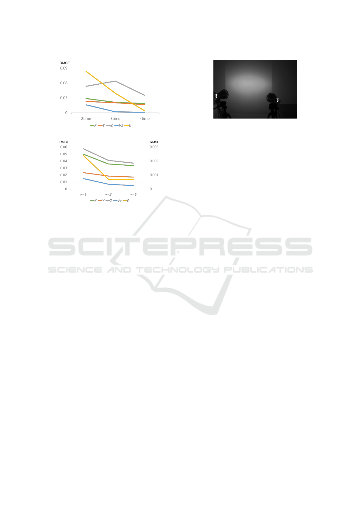
(a) Number of observation times.
(b) Moving speed of luminous objects.
Figure 4: Relationship between the number of observation
times, the moving speed of luminous objects, and the accu-
racy of estimation (RMSE).
points is 57 for face1 and 55 for face 2, so the infor-
mation to be recovered is 57 × 7 for face1 and 55 × 7
for face2. Thus, we have a sufficient number of ob-
servations for 3D reconstruction.
The 3D shapes and luminance distributions re-
covered by using the proposed method are shown in
Fig. 3 (c). Comparing (a) with (c), we find that both
the 3D shape and the luminance distribution can be
estimated quite accurately. These results show that
the 3D shape of an occluded object and its lumi-
nance distribution can be recovered from indirect im-
age observation through a wall by using the proposed
method.
5.2 Quantitative Evaluation
We next present the results of a quantitative evaluation
of the proposed method using synthetic images.
In the proposed method, reconstruction can be
performed with observations at a minimum of two
time instants, but it can be expected that the more time
images are used, the more information will be ob-
tained and the better estimation will be made. There-
fore, we evaluated the estimation accuracy while in-
creasing the number of times used from 2 to 4.
Fig. 4 (a) shows the change in accuracy (RMSE)
of estimated shape (X, Y, Z ), luminous intensity E,
and velocity V
z
. As can be seen from this figure, in-
Figure 5: Experimental setup. Two light sources were
used, and the intensity of the wall illuminated by these light
sources was observed with a camera.
creasing the number of observation times significantly
improves the accuracy of estimation of both shape, lu-
minous intensity, and velocity.
We next evaluate the change in accuracy due
to differences in the motion speed of the luminous
object. Fig. 4 (b) shows the estimation accuracy
(RMSE) when the moving speed is 5cm, 10cm, and
25cm per frame. The left scale of the graph repre-
sents position (X, Y, Z) and velocityV
z
errors, while
the right scale represents light source luminance E er-
rors. From this graph, we find that the estimation ac-
curacy is also highly dependent on the speed at which
the object is moving.
5.3 Real Image Experiments
We next show reconstruction results from real images.
In this experiment, a visible light camera was used
to perform a 3D reconstruction of an object emitting
visible light.
Fig. 5 shows the experimental setup used in this
experiment. As shown in the figure, two light sources
were used, and the intensity of the wall illuminated
by these light sources was observed with a camera to
reconstruct the light source position, luminance inten-
sity, and light source motion. Since the luminance of
these light sources can be varied, the luminance of the
two light sources were set to different values.
These light sources were moved at arbitrary
speeds, and images were taken at two time instants
before and after the motion. To eliminate the influ-
ence of ambient light, we also acquired an image with
the light source off and subtracted from the image
with the light source on to obtain an image illumi-
nated only by the light source.
Since our method is invariant to the reflectance
of the intermediate observation surface and is not
affected by the texture on the surface, we tested
our method using five different walls as interme-
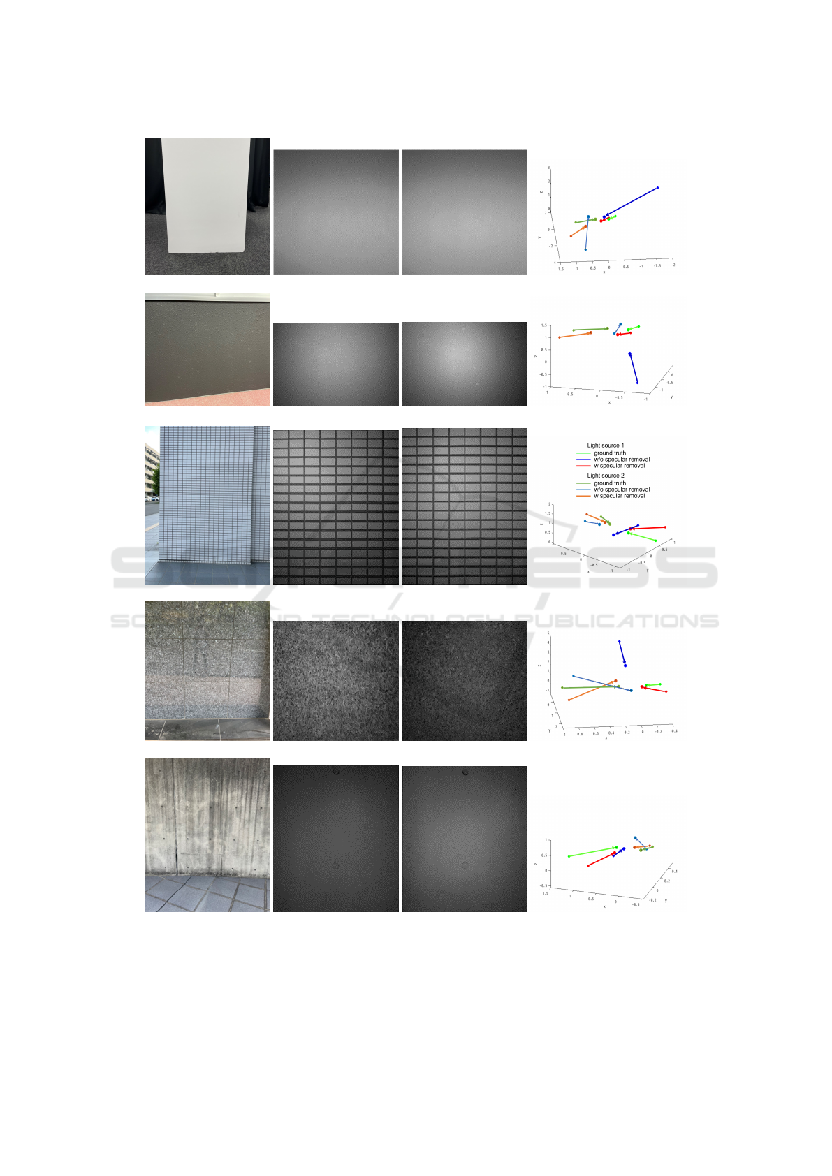
diate observation surfaces. Fig. 6 (a) shows five
different walls used in this experiment, which are
VISAPP 2023 - 18th International Conference on Computer Vision Theory and Applications
994
Smooth surface
Rough surface
Lattice surface
Mirror surface
Concave surface
(a) observation surface (b) image before motion (c) image after motion (d) estimated motion
Figure 6: Observation surfaces, observed images, and recovered light source motions in real image experiment. Points and
arrows in (d) show the position and motion of light sources.
3D Reconstruction of Occluded Luminous Objects
995

Table 1: Comparison of restoration accuracy (RMSE) by
removal of specular reflection component
before removal after removal
(m) (m)
Smooth surface 4.759 1.555
Rough surface 8.068 1.716
Lattice surface 9.325 2.474
Mirror surface 7.633 1.853
Concave surface 7.412 1.989
smooth surface, rough surface, lattice surface, sur-
face with strong specular reflection component (mir-
ror surface), and concave surface. For removing the
specular components by using the method shown in
section 4, network training was performed with 720
training data and 180 test data.
Fig. 6 (b) and (c) show the observed images be-
fore the specular component removal, and Fig. 6 (d)
shows the estimated results of the 3D light source
positions before and after light source motion. The
points and arrows show the position and motion of the
light sources. Light and dark colors represent the first
and second light sources respectively. The green ar-
rows represent the ground truth light source motions,
the blue arrows represent the light source motions re-
covered from the images before the specular compo-
nent removal, and the red arrows represent the light
source motions recovered from the images after the
specular component removal. As shown in this fig-
ure, the proposed method can recover the occluded
light source positions and motions from the indirect
intensity on many different types of walls. This is
because the proposed method uses the reflectance in-
variant for estimating the occluded light sources. In
particular, the red arrows are closer to the green ar-
rows, so we find that the specular component removal
is effective in our method.
Table 1 compares the RMSE of the results recov-
ered from the images before and after the specular
component removal for each intermediate observation
surface. From this table, we find that the accuracy
of the estimation is drastically improved by removing
the specular components using the method shown in
section 4.
6 CONCLUSIONS
In this paper, we proposed a method for recovering
the 3D structure and luminance distribution of lumi-
nous objects that cannot be directly observed from the
camera. For this objective, we modeled the observa-
tion process of the light emitted from a luminous ob-
ject, reflecting off walls and floors and reaching the
camera. Then, we showed that 3D shape and lumi-
nance distribution can be estimated simultaneously by
using images obtained at multiple time instants. Ex-
periments with synthetic and real images confirmed
that the proposed method works under many different
types of intermediate walls.
REFERENCES
Baradad, M., Ye, V., Yedidia, A. B., Durand, F., Freeman,
W. T., Wornell, G. W., and Torralba, A. (2018). In-
ferring light fields from shadows. In Proceedings of
the IEEE Conference on Computer Vision and Pattern
Recognition, pages 6267–6275.
Bouman, K. L., Ye, V., Yedidia, A. B., Durand, F., Wornell,
G. W., Torralba, A., and Freeman, W. T. (2017). Turn-
ing corners into cameras: Principles and methods. In
Proceedings of the IEEE International Conference on
Computer Vision, pages 2270–2278.
Chen, W., Daneau, S., Mannan, F., and Heide, F. (2019).
Steady-state non-line-of-sight imaging. In Proceed-
ings of the IEEE/CVF Conference on Computer Vision
and Pattern Recognition, pages 6790–6799.
Isola, P., Zhu, J.-Y., Zhou, T., and Efros, A. A. (2017).
Image-to-image translation with conditional adversar-
ial networks. In Proceedings of the IEEE conference
on computer vision and pattern recognition, pages
1125–1134.
Kaga, M., Kushida, T., Takatani, T., Tanaka, K., Funatomi,
T., and Mukaigawa, Y. (2019). Thermal non-line-of-
sight imaging from specular and diffuse reflections.
IPSJ Transactions on Computer Vision and Applica-
tions, 11(1):1–6.
Maeda, T., Wang, Y., Raskar, R., and Kadambi, A. (2019).
Thermal non-line-of-sight imaging. In 2019 IEEE In-
ternational Conference on Computational Photogra-
phy (ICCP), pages 1–11. IEEE.
Mirza, M. and Osindero, S. (2014). Conditional generative
adversarial nets. arXiv preprint arXiv:1411.1784.
Saunders, C., Murray-Bruce, J., and Goyal, V. K. (2019).
Computational periscopy with an ordinary digital
camera. Nature, 565(7740):472–475.
Velten, A., Willwacher, T., Gupta, O., Veeraraghavan, A.,
Bawendi, M. G., and Raskar, R. (2012). Recovering
three-dimensional shape around a corner using ultra-
fast time-of-flight imaging. Nature communications,
3(1):1–8.
Yedidia, A. B., Baradad, M., Thrampoulidis, C., Freeman,
W. T., and Wornell, G. W. (2019). Using unknown
occluders to recover hidden scenes. In Proceedings
of the IEEE/CVF Conference on Computer Vision and
Pattern Recognition, pages 12231–12239.
VISAPP 2023 - 18th International Conference on Computer Vision Theory and Applications
996
