
Ultra-Low Power Electronic Circuits Inspired by Biological Genetic
Processes
Ilan Oren, Raghd Abu-Sinni and Ramez Daniel
Faculty of Bio-Medical Engineering, Technion - Israel Institute of Technology, Haifa 3200003, Israel
Keywords:
Subthreshold Electronic Circuits, Analog Design, Neural Network, Molecular Network, Bio-Inspired.
Abstract:
Neuromorphic engineering, inspired by principles and architecture of neuronal circuitries, enabled the design
of Artificial Neural networks (ANNs) for Intelligent systems. These systems perform very complex computa-
tion tasks, yet they consume significant power. Thus, using artificial intelligence (AI) for applications where
only a small power source is available is very limited. While the neuronal networks in the brain can recognize
complex patterns and memorize enormous elements, molecular and protein networks can perform other com-
plex tasks such as adaptive immunity and cell differentiation at high energy efficiency. Here, we claim that a
bio-inspired computing platform mimicking molecular protein networks can lead to ultra-low power emergent
computation. Previously, we proposed a molecular-inspired computing model named Perceptgene that has the
attributes of learning and adaptivity as the neural network (Rizik et al., 2022). Similarities were found be-
tween equations describing biochemical reactions and transistor operation at subthreshold (Sarpeshkar, 2011)
enabling the design of Perceptgene with subthreshold electrical circuits. Thus, the subthreshold Perceptgene
circuits are expected to allow computing and learning capabilities at ultra-low power consumption.
1 INTRODUCTION
Biological neural systems are comprised of remark-
able parallel and distributed computing networks with
adaptive, self-repairing, and replicative capacities in
the performance of real-world tasks. Scientists and
engineers have been inspired to mimic these features
when designing artificial intelligence systems. Neu-
romorphic computing (Mead, 1990) applies abstract
models of neural systems, such as the perceptron
(Haykin, 2004), and uses microelectronics to build
artificial intelligent machines. Today, the world is in-
creasingly dependent upon this artificial intelligence
(AI) and machine learning (ML) systems in several
fields. Among these fields are health and finance, face
and object recognition, command of autonomous ve-
hicles, speech recognition, and natural language pro-
cessing. However, the power consumption of cur-
rent deep-learning machines and ‘layered neural net-
works’ is one of the most challenging limitations
of these systems. The steep increase in their en-
ergy consumption and the computing power required
for training them, which has grown 300,000-fold be-
tween 2012-18, are both unsustainable, putting sub-
stantial applications beyond the reach of all but well-
resourced organizations. While the brain can perform
sophisticated information processing by employing
complex neuronal circuit topologies with highly inter-
connected nodes, molecular biological systems con-
tain extensively noisy parts that collectively interact
to solve parallel tasks online with high energy effi-
ciency. A single cell in the body, for example, per-
forms 10 million energy-consuming biochemical op-
erations per second on its noisy molecular inputs at
1pW of average power (Sarpeshkar, 2010). In this
study, we propose ultra-low power electronic cir-
cuits inspired by gene networks to demonstrate
the computational abilities of neuronal networks.
This approach relies on insights we have gained
that map neuronal networks to molecular biologi-
cal systems (biomorphic (Rizik et al., 2022) (Daniel
et al., 2013)) and then to electronic circuits (cyto-
morphic (Sarpeshkar, 2011) (Hanna et al., 2020) ),
as shown in Fig. 1. The proposed computational ap-
proach is realized by building subthreshold electronic
circuits mimicking molecular networks based on the
Perceptgene model [1]. We anticipate that subthresh-
old Perceptgene circuits will enable the implementa-
tion of an adaptive system with ultra-low power com-
putation abilities.
150
Oren, I., Abu-Sinni, R. and Daniel, R.
Ultra-Low Power Electronic Circuits Inspired by Biological Genetic Processes.
DOI: 10.5220/0011707800003414
In Proceedings of the 16th International Joint Conference on Biomedical Engineering Systems and Technologies (BIOSTEC 2023) - Volume 1: BIODEVICES, pages 150-156
ISBN: 978-989-758-631-6; ISSN: 2184-4305
Copyright
c
2023 by SCITEPRESS – Science and Technology Publications, Lda. Under CC license (CC BY-NC-ND 4.0)
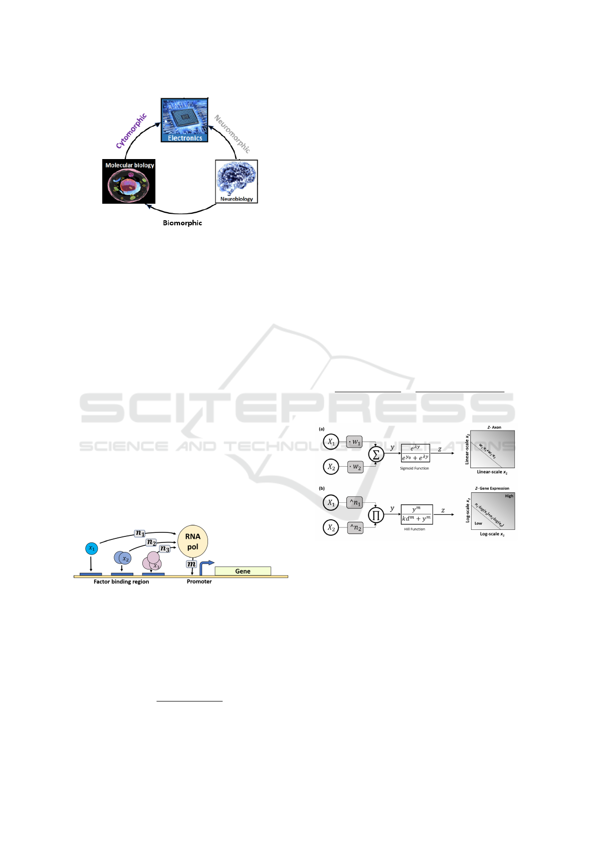
Figure 1: From Biomorphic to cytomorphic. Biomorphic:
implementation of neural networks into synthetic molecu-
lar networks. Cytomorphic: implementation of molecular
networks into electronics. Neuromorphic: implementation
of the neural network into electronics.
2 BIO-MOLECULAR ”NEURON”
Our neural model was inspired by combinatorial gene
regulation kinetics of promoter activation (Fig. 2) . A
combinatorial promoter is regulated by multiple tran-
scription factors x
i
, each transcription factor binds to
its designated region and afterward participates in re-
cruiting the RNA polymerase to form the activation
complex. In our model, several biological parame-
ters are involved, such as the biological cooperativ-
ity of proteins, the number of binding sites in the
promoter, the protein quaternary structure, and the
binding affinities of protein-protein/protein-DNA re-
actions. In this process, multiple transcription factors
participate and bind upstream to a gene sequence. To-
gether they facilitate the binding of RNA polymerase
to the promoter region forming the activation complex
which initiates gene transcription.
Figure 2: Anatomy structure of operating principles of gene
regulatory network.
For a combinatorial activation, the relation be-
tween the transcription factors concentration and the
promoter transcription rate, under certain conditions
(Bintu, 2005), can be simplified and modeled as fol-
lows:
P =
(
∏
N
i
x
n
i
i
)
m
(
∏
N
i
x
n
i
i
)
m
+ kd
m
(1)
Where P is the activation rate, x
i
is the transcrip-
tion factor concentration, n
i
is the Hill coefficient of
transcription factor i associated with the activation
complex formation, m is the Hill coefficient for the
binding of the activation complex with the promoter
and kd is the dissociation constant for the complex
binding with the promoter.
By applying a logarithmic transform to Eq. 1, we
obtain a new abstract model analogous to the percep-
tron model that is used in artificial neural networks
(Fig. 3a). Similar to other artificial neuron models that
operate as binary classifiers, this model achieves clas-
sification via a weighted input integration followed by
a threshold activation for the output. However, three
notable differences exist. First, the weighing of the
inputs is done here according to a power law and not
multiplication. Second, the inputs are integrated via a
product rather than a summation. And third, the ac-
tivation function used for this model is the Hill equa-
tion instead of the standard logistic function. Inter-
estingly the perceptgene model can be viewed as a
perceptron (Fig. 3) with a log transform over its input
dynamic range, the proof is straightforward from the
following equality:
P =
(
∏
N
i
x
n
i
i
)
m
(
∏
N
i
x
n
i
i
)
m
+ kd
m
=
e
m
∑
N
i
n
i
Ln(x
i
)
e
m
∑
N
i
n
i
Ln(x
i
)
+ e
mLn(kd)
(2)
Figure 3: Abstract artificial intelligence models for (a) per-
ceptron inspired by neural networks: x
i
are the inputs, w
i
are
multiplicative weights, input integration is done via sum-
mation, and the activation function is the sigmoid function.
Depicted on the right is the resulting linear separable clas-
sification of the analog inputs x1 and x2 (b) perceptgene
inspired by genetic networks: x
i
are the inputs, n
i
are power
weights, input integration is done via a product, and the acti-
vation function is the Hill equation. Depicted on the right is
the resulting logarithmically separable classification of the
analog inputs x1 and x2.
Ultra-Low Power Electronic Circuits Inspired by Biological Genetic Processes
151
3 PERCEPTGENE CIRCUIT
CONCEPT
Analogous to perceptron implementation using ana-
log linear circuits (e.g., resistors), we implement
the Perceptgene using analog logarithmic circuits.
Specifically, we use translinear analog circuits
(Gilbert, 1975) with MOSFET transistors operating
at the subthreshold region. The circuits implement
power-law and multiplication functions for the input
signals, while a nonlinear activation function circuit
generates the output result. The proposed analog cir-
cuit for implementing the Perceptgene model as can
be seen in Fig. 3b includes three subcircuits: 1. Power
circuit – to implement the power (n1, n2) function
over X1, X2 inputs 2. Multiplication circuit – to mul-
tiply the output of the power circuits 3. Activation
function – a decision-making circuit based on the Hill
equation
The analog subcircuits are translinear circuit that
operates at the subthreshold region. The operation at
the subthreshold region ensures that the current of the
transistors depends exponentially on the voltage be-
tween the gate and the source of the transistor (Eq. 3).
The translinear circuits follow the Trans Linear Prin-
ciple (TLP) which refers to the summation of volt-
ages with exponential dependency over closed loops.
On these circuits, the product of the currents through
the clockwise Translinear Elements (TEs) equals the
product of the currents through the counter-clockwise
TEs (Eq. 4). The usage of translinear subthreshold
circuits enables us to implement the arithmetic func-
tion needed for Perceptgene at ultra-low power.
Ids = I
0
· Exp
(V
GS
−V
th
)
U
T
(3)
Cw{π(I
n
)} = CCw{π(I
n
)} (4)
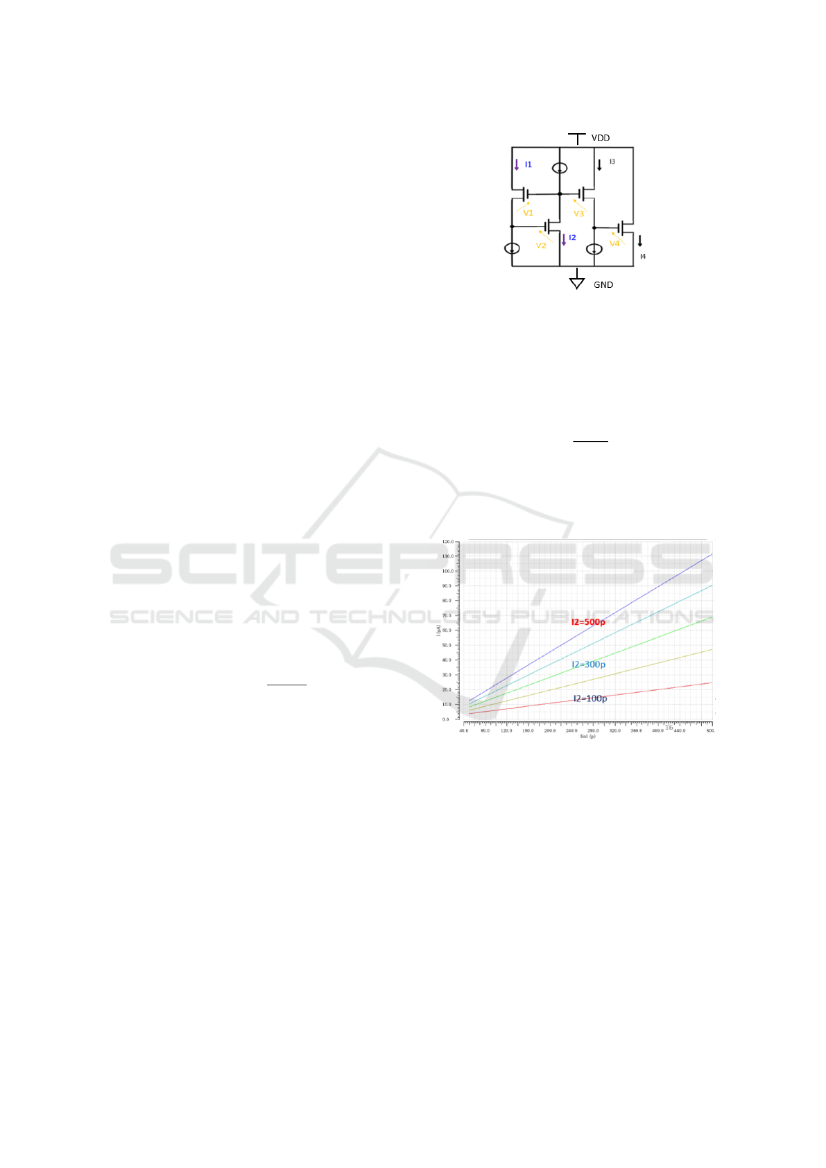
3.1 Multiplication Circuit
The purpose of the multiplication circuit is to imple-
ment the multiplication function between the outputs
of the power circuits. An illustration of the proposed
translinear subthreshold analog circuit for implement-
ing the multiplication can be viewed in Fig. 4. Since
all the transistors operate in the subthreshold region,
the current through them is exponentially influenced
by their gate-source voltage. According to KVL, the
voltages of the transistors sums up over a closed loop.
The log summation of the voltages over a closed-loop
turns into a multiplication of currents (Eq.5) as ex-
pected according to the TLP. Thus, for input currents
I1,I2, and a constant current I3 we get the required
functionality.
Figure 4: Multiplication subthreshold translinear circuit.
V
1
+V
2
−V
3
−V
4
= 0
ln(I1) +ln(I2) − ln(I3) − ln(I4) = 0
I4 =
I1 ∗ I2
I3
(5)
Spice sweep simulations (Fig. 5) with I3=100pA
and a I1, I2 varying from 100pA to 500pA resulted
in the expected behavior of multiplication between I1
and I2.
Figure 5: Multiplication circuit simulations.
3.2 Power Circuit
The goal of the power circuit is to implement the
power (n1, n2) function over the input signals X1 and
X2. An illustration of the proposed translinear sub-
threshold analog circuit which implements the power
function can be viewed in Fig. 6.
The power circuit is similar to the multiplication
circuit except for the resistors (R1, R2) which are con-
nected to the device’s gates. These resistors are con-
nected as voltage dividers and thus define the Vgs of
the transistors (Eq. 6). The relation between these re-
sistors will be used to define the power constant n1,
n2 (Eq. 7)
BIODEVICES 2023 - 16th International Conference on Biomedical Electronics and Devices
152
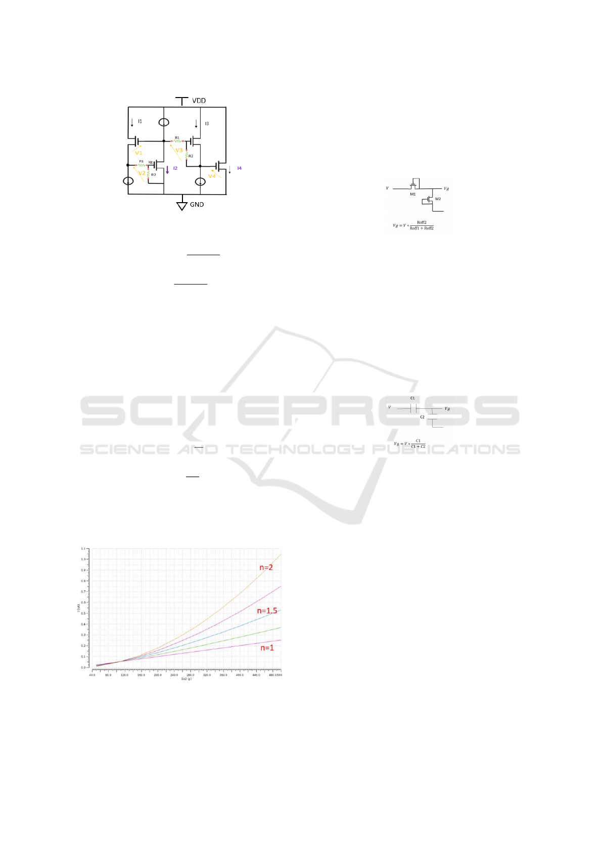
Figure 6: Power subthreshold translinear circuit.
V gs = V ∗
R2
R1 + R2
(6)
n =
R1 + R2
R2
(7)
Due to the operation in the subthreshold region,
the current is an exponential function of the Vgs volt-
age which is set by the ratio of the resistors. Thus we
get a voltage that is a function of the power (n) of the
current (Eq. 8)
V = ln(Ids
n
) (8)
Summation of the voltages over a closed loop and
a constant reference current (I1, I3) will then give the
power (n) dependency between the input (I2) and the
output (I4) currents (Eq. 9) as required.
I4 = I1 ∗ (
I2
I3
)
n
I4 = (
I2
n
K
) (9)
Spice sweep simulations (Fig. 7) with I3=200pA
, I1=100pA and Iin varying from 50pA to 500pA re-
sulted in the expected behavior of a power function
for different n values.
Figure 7: Power circuit simulations.
To insure minor currents through the voltage di-
viders the value of the resistors (R1,R2) should be
extremely high. The ability to design Giga ohms
pseudo-resistors using transistors was already demon-
strated ((Kassiri et al., 2013), (Puddu et al., 2016)).
Our implementation of the voltage dividers might also
include transistors or capacitors instead of resistors as
can be viewed in Fig. 8 and Fig. 9 below.
Figure 8: Transistors Voltage dividers.
The transistors implementation of the voltage di-
vider (Fig. 8) includes transistors that operate at a
subthreshold region and thus demonstrate huge resis-
tivity. For deep subthreshold or cut-off connectivity
where Vgs=0 the resistance can get to hundreds of
Giga Ohms. The sizes of these transistors which are
connected in series will define the exact amount of
voltage divider which is implemented. The main chal-
lenge of this implementation is its sensitivity due to
the exponential dependency of the current and thus
the resistance in threshold voltage Vt.
Figure 9: Capacitors Voltage dividers.
The capacitors implementation of the voltage di-
vider (Fig. 9) includes capacitors that are connected
in series. The capacitors are charged to different volt-
age values based on their capacitance thus creating
a voltage divider with 0 dc current as required. The
main challenge of this implementation is the need to
deal with the dynamic behavior of the divider which
might require extra switches for discharging the ca-
pacitors. On both implementations of the voltage di-
vider, the n power coefficient of the circuit will be
tuned by changing the capacitor or transistor sizes.
3.3 Activation Function Circuit
The Activation Function (AF) Circuit is a decision-
making circuit implementing the Hill function (Eq. 1)
and it generates the result based on multiplication cir-
cuit output. The nonlinear activation function circuit
previously suggested in (Daniel et al., 2011) is based
on a differential amplifier and 2 current mirrors as il-
lustrated in Fig. 10.
Due to the symmetry of the circuit and the current
Ultra-Low Power Electronic Circuits Inspired by Biological Genetic Processes
153
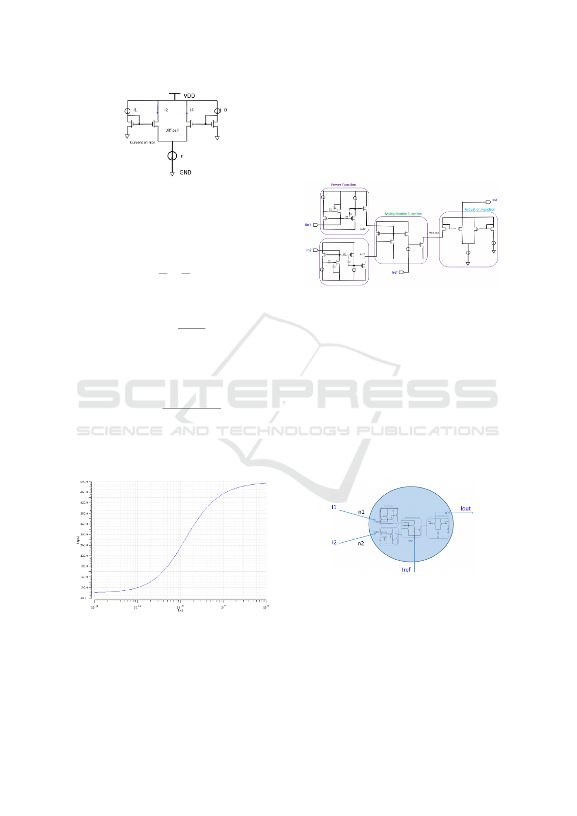
Figure 10: Activation function circuit.
mirrors, the ratio of the currents can be defined by
(Eq. 10) The total current (It) of the differential pair
is the summation of the currents on its branches and
thus we get an output current (Eq. 11) which follow
the Hill equation.
I2
I1
=
I4
I3
(10)
I t = I2 + I4
I2 = It ∗
I1
I1 + I3
(11)
The output current I2 is a nonlinear function of
input current I1. When operated on the log scale we
get the sigmoid activation function described in Eq.
12 below.
I2 = It ∗
e
Ln(I1)
e
Ln(I1)
+ e
Ln(I3)
(12)
Fig. 11 shows the spice simulation results of the
circuit. In that simulation, I1 varying from 10pA to
1nA (while It=500pA, I3=100pA) and the result in
the log domain shows the expected sigmoid behavior.
Figure 11: Activation circuit simulations.
3.4 Full Perceptgene Circuit
The circuits described in the previous sections were
integrated into the full Perceptgene circuit as can be
seen in Fig. 12 below. The full Perceptgene circuit
includes 2 power function circuits a multiplier and an
AF circuit. The 2 input currents Iin1 and Iin2 are be-
ing processed by the circuit to generate the output cur-
rent Iout. The Weights of the Perceptgene can be con-
figured by changing the voltage dividers values and
the Bias can be configured by changing the Iref cur-
rent of the multiplier.
Figure 12: Full Perceptgene circuit.
As expected, due to its subthreshold operation,
simulations of the circuit resulted in ultra-low power
consumption ranging from a few to hundred nano
Watts depending on the inputs and usage.
4 BASIC CLASSIFIER AND ANN
IMPLEMENTATION
To build an ANN network, the perceptgene circuit
needs to demonstrate its classification capabilities.
Thus basic classifiers were implemented using a sin-
gle neuron ANN realized by perceptgene circuit (Fig.
13).
Figure 13: Single neuron classifier.
The first single perceptgene classifiers imple-
mented two inputs OR/AND logic functions. Those
functions were created by configuring the weights
(R1, R2) and the bias (Irefm) of the perceptgene cir-
cuit. The following simulation results in Fig. 14 show
that the circuit function as AND classifier when using
the correct weights.
Spice simulation results of a perceptgene circuit in
which the weights and bias were set to create an OR
BIODEVICES 2023 - 16th International Conference on Biomedical Electronics and Devices
154

Figure 14: Two inputs AND simulations.
function can be viewed in Fig. 15 below.
Figure 15: Two inputs OR simulations.
From a single perceptgene classifier we move to
a multi-layer ANN implementation. An example of
such ANN can be viewed in Fig. 16. The three inputs
ANN includes three perceptgene cells organized in
two layers to implement the majority function when
the correct weights (n1-n8) are set. The majority
function is a logic function in which its output is
high when the majority of its inputs are high. Find-
ing the weights (n1-n8) which will enable the ANN
to execute the majority function required the use of
a Back-Propagation Gradient-Descend (BPGD) algo-
rithm. Due to differences between the perceptron and
the perceptgene a special version of the BPGD algo-
rithm was developed.
Figure 16: Three inputs Majority ANN.
In the Back-Propagation Gradient-Descend algo-
rithm, the inputs are fed to the ANN and the weights
are tuned based on the difference between the actual
result at its output vs. the expected result. The al-
gorithm search for the required weights of the ANN
which provide the minimum error as can be viewed in
Fig. 17.
The BPGD algorithm was tuned to operate in the
log domain to fit the perceptgene operation. Thus the
LOG of the error is calculated as can be viewed in Eq.
13.
Error = 1/2 ∗ Log(
Out put
Actual
Out put
Expected
)
2
(13)
The tuned BPGD algorithm was used successfully
Figure 17: Gradient descends algorithm.
to build a few other multi-layer ANN which imple-
ments logic functions such as Muxes and full-adders.
5 CONCLUSION
We propose ultra-low power electronic circuits in-
spired by gene networks to demonstrate the compu-
tational abilities of neural networks. These circuits
were implemented using MOSFET devices operat-
ing at the sub-threshold region. Basic training abil-
ities for two and three inputs perceptgene networks
were demonstrated. This study presents an energy-
efficient bio-inspired platform that allows ANN com-
puting with learning capabilities
ACKNOWLEDGEMENTS
We gratefully acknowledge the financial support by
the Israel Ministry of Science (MOS) through grant
3-14364
REFERENCES
Bintu, L. (2005). Transcriptional regulation by numbers:
models. Curr Opin Genet.
Daniel, R., Rubens, J., Sarpeshkar, R., and Lu, T. (2013).
Synthetic analog computation in living cells. Nature.
Daniel, R., Woo, S., Turicchia, L., and Sarpeshkar, R.
(2011). Analog transistor models of bacterial genetic
circuits. IEEE biomedical circuits and systems con-
ference (BioCAS).
Gilbert, B. (1975). Translinear circuits: a proposed classifi-
cation. Electron Lett.
Hanna, H., Danial, L., Kvatinsky, S., and Daniel, R. (2020).
Cytomorphic electronics with memristors for model-
ing fundamental genetic circuits. IEEE Transactions
on Biomedical Circuits and Systems.
Haykin, S. (2004). Neural networks: A comprehensive
foundation. Pearson Education.
Kassiri, H., Abdelhalim, K., and Genov, R. (2013). Low-
distortion super-gohm subthreshold-mos resistors for
cmos neural amplifiers. Biomedical Circuits and Sys-
tems Conference (BioCAS).
Ultra-Low Power Electronic Circuits Inspired by Biological Genetic Processes
155

Mead, C. (1990). Neuromorphic electronic systems. Proc
IEEE.
Puddu, R., Carboni, C., Bisoni, L., Barabino, G., D.Pani,
L.Raffo, and Barbaro, M. (2016). A precision pseudo
resistor bias scheme for the design of very large time
constant filters. IEEE Transactions on Circuits and
Systems.
Rizik, L., Danial, L., Habib, M., Weiss, R., and Daniel, R.
(2022). Synthetic neuromorphic computing in living
cells. Nature communications.
Sarpeshkar, R. (2010). “the big picture: Ultra-low power in-
formation processing in biology. In Ultra Low Power
Bioelectronics. Cambridge University Press.
Sarpeshkar, R. (2011). “cytomorphic electronics: cell-
inspired electronics for systems and synthetic biology.
In Ultra Low Power Bioelectronics. Cambridge Uni-
versity Press.
BIODEVICES 2023 - 16th International Conference on Biomedical Electronics and Devices
156
