
Application of a Process-Oriented Build Tool for Verification and
Validation of a Battery Slave Controller for a Battery Modular Multilevel
Management System Along the DO-178C/DO-331 Process
Purav Panchal
1
, Nina Sorokina
2
, Manuel Kuder
2
, Stephan Myschik
1
, Konstantin Dmitriev
3
and Florian Holzapfel
3
1
Institute for Aeronautical Engineering, Universit
¨
at der Bundeswehr M
¨
unchen, 85521 Neubiberg, Germany
2
Department of Electrical Engineering, Universit
¨
at der Bundeswehr M
¨
unchen, 85521 Neubiberg, Germany
3
Institute of Flight System Dynamics, Technische Universit
¨
at M
¨
unchen, 85748 Garching, Germany
{konstantin.dmitriev, florian.holzapfel}@tum.de
Keywords:
Process Oriented Build Tool, Model-Based Design, Modeling Guidelines, Naming Convention, Model
Coverage, Code Coverage, Cyclomatic Complexity, Build Automation, Model Standards, DO-178C, DO-331.
Abstract:
Software development of safety-critical systems is accompanied with strict methodologies, handling of a large
number of artifacts, and transparent verification activities. In order to achieve compliance to the DO-178C/DO-
331 standard. These requirements reduces the flexibility of the development and demands highly skilled per-
sonnel. This increases both money and time requirements. To address this problem, a process-oriented build
tool has been developed and applied to safety-critical applications, such as flight control algorithms. Advan-
tages of this build-tool include automatic verification jobs, interlinking of tools, artifact handling, bottom-to-
top code generation, change impact analysis, handling of multiple modules, etc. In this paper, the build tool
is used to develop and verify a battery slave controller for a Battery Modular Multilevel Management (BM3)
module. This paper presents the important verification results achieved, including model coverage, code cov-
erage and cyclomatic complexity of the slave controller. These results help in demonstrating the mentioned
advantages of the use of the build-tool and provides a practical application point of view.
1 INTRODUCTION
Safety in general is defined as ‘freedom from those
conditions that can cause death, injury, illness, dam-
age to or loss of equipment or property, or environ-
mental harm’ (Rierson, 2017). As humans become
more dependent on technology for comfort and living,
the risk of harm caused by technology also increases.
Hence, the safety aspect of technology must be con-
sidered thoroughly. Systems that have an impact
on human safety upon failure are defined as safety-
critical systems. Examples of safety-critical systems
are found in aerospace, automotive, railway, medi-
cal and nuclear applications. Failure of software in
safety-critical systems has resulted in numerous loss
of human lives in the past (Macola, 2021; Mamiit,
2015). Therefore, this type of software must be tested
extensively according to the respective standards.
Assuring the safety of the software is not a hassle-
free task as this requires lot of regulations and strict
methodologies to be followed according to the certifi-
cation standards resulting in extensive documentation
and efforts. Strict methodologies reduces the flexi-
bility of incorporating changes in requirements at a
later stage, for example, adding a new feature after
certification is expensive and efforts consuming. This
problem, known as the ‘big-freeze’ problem (Cleland-
Huang et al., 2021), places a burden on small-scale
companies due to their limited resources. Information
on tool interlinking and setup is usually a part of intel-
lectual property of the large scale companies, further
hindering the progress of small scale companies and
also affecting the overall advancement of technology,
especially in the industries of electrical aviation, as
well as unmanned aerial vehicles (UAVs) and electric
vertical take-off and landing (eVTOL) systems.
To tackle above mentioned problems, a process-
oriented build tool called ‘mrails’ has been devel-
oped and used in several complex flight control and
avionics software development projects at the Insti-
tute of Flight System Dynamics at Technical Uni-
versity of Munich and the Institute for Aeronautical
184
Panchal, P., Sorokina, N., Kuder, M., Myschik, S., Dmitriev, K. and Holzapfel, F.
Application of a Process-Oriented Build Tool for Verification and Validation of a Battery Slave Controller for a Battery Modular Multilevel Management System Along the DO-178C/DO-331
Process.
DOI: 10.5220/0011696100003402
In Proceedings of the 11th International Conference on Model-Based Software and Systems Engineering (MODELSWARD 2023), pages 184-193
ISBN: 978-989-758-633-0; ISSN: 2184-4348
Copyright
c
2023 by SCITEPRESS – Science and Technology Publications, Lda. Under CC license (CC BY-NC-ND 4.0)

Engineering at Universit
¨
at der Bundeswehr M
¨
unchen
(Hochstrasser et al., 2018; Hochstrasser, 2020). The
‘mrails’ build tool supports software development of
safety-critical applications using model-based soft-
ware development approach in MATLAB, Simulink
and Stateflow across various stages. Development
of the ‘mrails’ build tool and its components are ex-
plained in (Hochstrasser et al., 2018; Dmitriev et al.,
2020). The ‘mrails’ build tool provides several key
advantages like artifacts scaffolding to enable dis-
tributed development, change impact analysis to per-
form incremental verification, automation of verifi-
cation activities developed across DO-178C/DO-331
standards, and complete traceability of artifacts.
Application of the build tool to develop a safety-
critical flight controller and avionics software is dis-
cussed in (Panchal et al., 2022b; Panchal et al., 2022c;
Hochstrasser et al., 2019). One of such application of
the build tool to develop the aforementioned battery
slave controller is discussed in (Panchal et al., 2022c)
and its verification part is continued in this paper.
The remainder of the paper is as follows: Sec-
tion 2 provides an overview of the ‘mrails’ build tool
and section 3 presents the battery modular multilevel
management system (BM3) (Kuder et al., 2020). Sec-
tions 3.2 and 4 discusses the design steps and verifica-
tion results like model and code coverage of the slave
controller. Lastly, section 5 and 6 discusses the future
work and main conclusion drawn from the results.
2 PROCESS-ORIENTED BUILD
TOOL
The process-oriented build tool is called ‘mrails’
and is based on modular model-based development
methodology. The tool provides a framework in
MATLAB and Simulink for the developers to cre-
ate models, generate code and perform design and
code verification. Modular software development
supports agile development and enables incorporation
of change in requirements. Moreover, the tool pro-
vides an HTML based status report that aggregates all
the results from respective jobs, including code gen-
eration, design and code verification, etc. The status
report provides traceability of artifacts related to the
particular job. The tool has an incorporated so called
lifecycle package that contains several containers that
help in creating model artifacts, including top-level
models, reusable models, Simulink bus, parameters,
constants, low-level and top-level test cases. The life-
cycle package also contains code generation, design
and code verification jobs. These jobs and contain-
ers are configured with taking into account the DO-
178C/DO-331 standards. The ‘mrails’ build tool not
only allows the execution of a dependency network of
tasks but also improves process conformance, consis-
tency and cleanliness of the software project.
2.1 Related Work
Application of this build tool has been presented in
two research papers: (Panchal et al., 2022b) presents
the development of an INDI flight controller for a hex-
acopter using the build tool, (Panchal et al., 2022c)
presents the development of slave controller and veri-
fication results including static model analysis, design
error detection, traceability review, simulation testing,
code compliance and code proving. This paper is an
extension of (Panchal et al., 2022c) covering the as-
pects of model and code coverage of the slave con-
troller.
Several papers have been published that address
the testing effort of the model and code especially
with respect to coverage analysis. A technical white
paper (GrammaTech, 2022) mentioned the signifi-
cance of static code analysis of the safety-critical sys-
tem, arguing that the code coverage analysis is expen-
sive and sometimes not sufficient to cover all cases,
and static analysis helps to overcome this disadvan-
tage. Another white paper (Rapita, 2022) presents a
tool to perform structural code coverage on embed-
ded hardware along DO-178B/C standards that shows
questions that the developers should be asked in order
to select the tool to perform code coverage.
(Brauer et al., 2015) addresses two main is-
sues that are faced during structural coverage anal-
ysis: source-object code traceability and data cou-
pling/control coupling analysis along with tools to
address these issues which are significant for DAL
A (Design Assurance Level) software. (Sun et al.,
2017) presents a method to generate automated tests
to reduce the testing efforts by using Bounded Model
Checking approach. An interesting research men-
tioned in (Bingol et al., 2014) shows how the required
software development time of safety-critical system
is reduced by applying reverse engineering, i.e., gen-
erating required certification artifacts from a devel-
oped software. The artifacts are generated according
to the DO-178C objectives. (Yinghui et al., 2011)
shows test coverage analysis of an airborne software
(TCAS - Traffic Alert and Collision Avoidance Sys-
tem) required according to the DO-178B standard.
(Olszewska et al., 2016) present a set of complexity
metrics for Simulink models and have compared them
with MathWorks metrics to realize the advantages of
their new complexity metrics.
Application of a Process-Oriented Build Tool for Verification and Validation of a Battery Slave Controller for a Battery Modular Multilevel
Management System Along the DO-178C/DO-331 Process
185
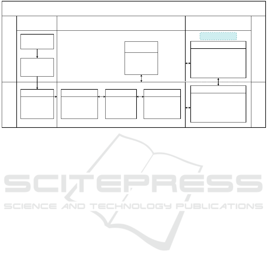
Process-Oriented Build Tool
Polarion and SimPol
Process
Definition
Define System
Requirements
Define Software
Requirements
Design and Build
Requirements
Allocation
SL Models
Test Cases
SL Data
Verification and
Validation
Code Verification
Inspect Code
Check Code Compliance
Code Defect Analysis
Code Proving
Code Coverage
Status Report
Polyspace
MATLAB/Simulink
Project Setup
Module ID
Sample Time
References
Data Dictionary
Interfaces
Parameters
Constants
Enums
Models
Singleton
Reusable
Top-Level
fsdlib
Build
Shared Code
Functional Code
Package Code
Design Verification
Static Model Analysis
Design Error Detection
Model Review
Simulation Case Execution
Model Coverage
MATLAB/Simulink
Figure 1: Workflow for the process-oriented build tool ‘mrails’.
2.2 Workflow
Figure 1 shows the workflow of the build tool
‘mrails’. System requirements are generated from the
customer requirements and respective system stan-
dards and software requirements are derived from
them. Requirements are stored in Siemens Polarion
tool (Siemens, 2004). Linking of Polarion work items
with MATLAB/Simulink artifacts is done using Sim-
Pol (TUM, 2018). Once software requirements are
defined, the build-tool mrails can be used for creating
a project in MATLAB.
The build tool provides several commands to cre-
ate MATLAB project with required folder structure
and configuration settings as described in the lifecy-
cle package. After designing the model, shared and
functional code can be generated using the build tool
commands.
Design and code verification is performed in par-
allel using different tools of MATLAB handled by the
build tool ‘mrails’. Design verification jobs include
static model analysis, design error detection, model
review, simulation case execution and model cover-
age. Code verification tasks like collecting code cov-
erage, checking code compliance, code proving, code
defect analysis and code inspection can be performed.
For all tasks, MATLAB/Simulink is always imple-
mented and other tools like Polarion, Polyspace and
SimPol are required as shown in the Figure 1. Results
of all the jobs are aggregated in a web-based HTML
report. The report has traceability feature through
which the artifacts can be traced to the affected jobs
and output.
Detailed workflow of the build tool ‘mrails’ is de-
scribed in (Hochstrasser et al., 2018; Hochstrasser,
2020; Panchal et al., 2022b; Panchal et al., 2022a;
Panchal et al., 2022c).
3 BM3 MODULE AND SLAVE
CONTROLLER DESIGN
3.1 BM3 Module
BM3 system is a battery management system intro-
duced by Bavertis (Bavertis, 2022). BM3 system
is based on an integrated 3-switch inverter topology
(Kuder et al., 2020; Kersten et al., 2019). Figure 2
shows a BM3 module with MOSFET switches rep-
resented by S1, S2 and S3 respectively. Terminals
‘A’,‘B’,‘C’ and ‘D’ are used to connect to the adja-
cent modules via power ports. The advantages of this
topology include flexible interconnections between
the battery cells to achieve optimum efficiency, match
required load voltage, increase lifetime and increase
fault tolerance of the system. Such kind of topology
provides three different states of the module: serial,
parallel and bypass. Bypassing defective cells helps
in increasing the life span of the battery pack and is
also a safety feature.
3.2 Battery Slave Controller Design
Figure 3 shows an overview of the battery pack with
controllers. The multilevel battery management sys-
MODELSWARD 2023 - 11th International Conference on Model-Based Software and Systems Engineering
186
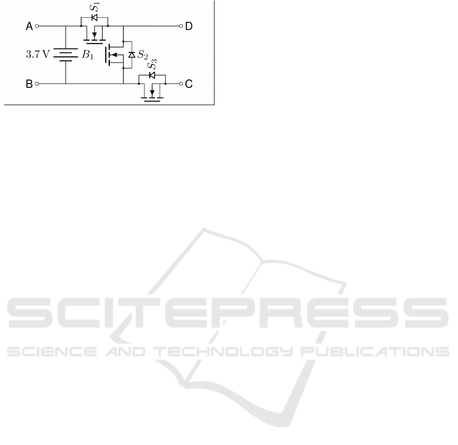
Figure 2: BM3 Module with MOSFETs (Kuder et al.,
2020).
tem consists of a master controller, several BM3 mod-
ules and each module is controlled by a slave con-
troller. The master controller receives all the neces-
sary information like current state of each cell (tem-
perature and voltage), error state from the switches,
current output of the battery pack and DC required
voltage via input and a feedback signal from the bat-
tery modules.
Depending on these inputs, the master calculates
required connection configuration of the BM3 mod-
ules and generates a configuration array which con-
tains the configuration selecting value for each mod-
ule. Depending on this value, the state of module is
determined, for example, series, parallel or bypass.
This configuration is set by the battery slave con-
troller. Figure 4 shows the Simulink model of the
slave controller logic. Designing steps and the logic
has been described in (Panchal et al., 2022c).
4 VERIFICATION AND
VALIDATION RESULTS
Verification of the designed slave controller is par-
tially discussed in the preceding paper (Panchal et al.,
2022c). The paper presented results from static model
analysis, design error detection, traceability review,
simulation testing, code compliance and code prov-
ing. In this paper, another aspects of the verification
task like model coverage, code coverage and cyclo-
matic complexity is discussed.
4.1 Significance of Model and Code
Coverage
Coverage analysis is used to determine how well a
program is executed according to the test cases. Re-
sult of coverage analysis shows how well the model or
code is exercised during the execution of the require-
ments based test cases. This helps in identifying unin-
tended functionalities, test completeness and require-
ments integrity. DO-178C Table A-7 addresses cov-
erage analysis objectives like requirements and struc-
tural coverage, required to be fulfilled. Two types of
coverage analyses are addressed in DO-178C:
1. Requirements Coverage Analysis: This analysis
shows that all the high-level and low-level re-
quirements are tested. Frequently, the change in
requirements at a later stage (big-freeze problem),
as discussed in Section 1, can lead to missing test
cases. Hence it is necessary to review the require-
ments coverage analysis incrementally whenever
the requirements are changed.
(a) High-level Requirement (HLR) Coverage
Analysis (DO-178C: Table A-7 Objective 3):
To prove that the HLRs are fully covered by
the test cases, the build tool ‘mrails’ contains a
checklist shown in Figure 5 used to perform the
test cases and procedures review. The checks
are derived from DO-331 MB.6.4.4.a (RTCA,
2011a; RTCA, 2011b). This analysis is valid if
all simulation cases are reused as test cases and
sufficient model coverage is achieved.
(b) Low-level Requirement (LLR) Coverage Anal-
ysis (DO-178C: Table A-7 Objective 4): Ac-
cording to DO-331 MB 6.7, the requirements-
based coverage for LLRs can be proved us-
ing model coverage as a means of compliance.
Since the test cases are derived from HLRs,
model coverage verifies the full execution of
the LLRs (design models) for the described
simulation test cases. Model coverage results
are discussed in section 4.2.
2. Structural Coverage Analysis: Basic meaning of
structural coverage is the quantity of code exe-
cuted or covered by running a single or multiple
tests. In the scope of certification, this analysis
shows if the code has been adequately exercised
during the requirements-based testing. Hence, it
ensures the tests are not derived from the code but
validated against requirements. Types of struc-
tural coverage analysis addressed by DO-178C:
(a) Statement Coverage (DO-178C: Table A-7 Ob-
jective 7): This coverage analysis ensures that
each statement of the program is executed
atleast once. However, it does not verify the
logic of the program and cannot cover false
conditions. For example, an if-else condition
will be executed if it is true but will not test the
false condition. Statement coverage is required
for Design Assurance Level (DAL) A, B and C.
(b) Decision Coverage (DO-178C: Table A-7 Ob-
jective 6): Decision coverage overcomes the
missing part of statement coverage i.e., it en-
Application of a Process-Oriented Build Tool for Verification and Validation of a Battery Slave Controller for a Battery Modular Multilevel
Management System Along the DO-178C/DO-331 Process
187
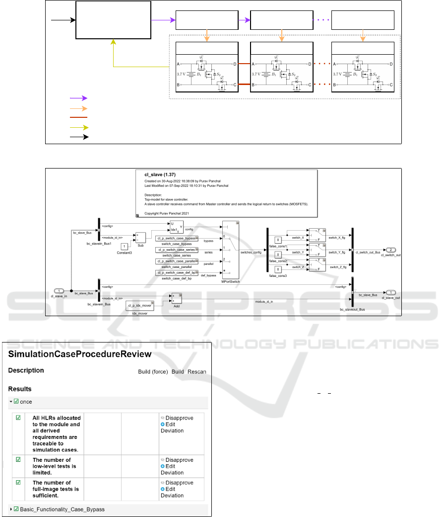
bc_slave_Bus
cl_switch_out_Bus
Power signal
Feedback signal
Inputs
Master Controller Slave Controller 1
Battery Module 1
Slave Controller 2
Battery Module 2
Slave Controller n
Battery Module n
Figure 3: Battery controller structure with signals and power connections.
Figure 4: Simulink model of the battery slave controller.
Figure 5: Requirements coverage analysis using the build
tool ‘mrails’.
sures that each statement is executed and if
there are Boolean expressions present, both the
true and false condition is executed via the
test cases. For example, in case of slave con-
troller as shown in Figure 4, if only one test
case that checks if the series state is executed
when required is used for verification, the de-
cision coverage for the model would not be
100%. This is because for series configuration
(S2 = 0, S1,S3 = 1), the Boolean output of the
switch ‘switch Y flg’ will be false and will not
be tested for a true condition. This is necessary
because the Boolean value will directly control
the switch, and therefore the configuration of
all the batteries and finally the output voltage of
the battery pack. Decision coverage is required
for DAL A software.
(c) Modified Condition/Decision Coverage
(MC/DC, DO-178C: Table A-7 Objective 5):
This type of coverage analysis is required
only for DAL A software. It analyzes how
the conditions within decisions independently
affect the outcome during execution.
(d) Data Coupling and Control Coupling Analy-
ses (DC/CC, DO-178C: Table A-7 Objective
8): Data coupling coverage analyzes depen-
dence of a software component on data not
exclusively under the control of that software
component and control coupling coverage ana-
lyzes the manner or degree by which one soft-
MODELSWARD 2023 - 11th International Conference on Model-Based Software and Systems Engineering
188

ware component influences the execution of an-
other component. According to DO-178C, the
DC/CC coverage ensures that the requirements-
based testing of integration model is com-
pletely exercised. There is no tool present yet
which provides this coverage result since it is
actually a collection of tasks that are to be
performed. Appendix A of the doctoral the-
sis (Hochstrasser, 2020) presents the review
and analysis of DC/CC coverage that mentions
the tasks provided by the build tool, results of
which can be aggregated to support the DO-
178C objective for DC/CC coverage.
4.2 Model Coverage
According to DO-331 MB 6.7, model coverage is
accepted as means of compliance for requirements-
based coverage for LLRs (DO-178C, Table A-7 Ob-
jective 4). The build tool uses Simulink Coverage
(MathWorks, 2022d) to calculate the model cover-
age. Applying structural code coverage analysis at
model level holds several advantages like identifying
if the simulation cases are enough, detecting unin-
tended and uncovered functionalities at early stage of
development. This analysis determines how well the
LLRs, design model in our case, is executed/covered
by the simulation cases derived from HLRs. When
these simulation cases are reused as test cases for
executable object code, compliance to requirements-
based test coverage is also achieved. The build tool
provides functionality to calculate model coverage
and aggregate them by calling command mrails mod-
elcoverageanalysis. Differentiating factor over here
is the automatic aggregation of the results from differ-
ent modules with incremental (change-based) analyis
(Hochstrasser et al., 2018).
For the mentioned application of slave controller,
Figure 6 shows the results of model coverage analy-
sis. Execution (also statement), condition and deci-
sion coverage results are displayed in the status re-
port. The results can be traced to the model via this
status report as shown in Figure 6.
4.3 Code Coverage
The build tool uses Simulink Coverage to calculate
the code structural coverage. This job is called by the
command mrails silcoverageanalysis. The tool fol-
lows its own approach of calculating the code cover-
age to make the process faster. Initially, software-in-
the-loop (SIL) test is performed using the Simulink
test cases with SIL settings. The code coverage
on host is done in this step. Secondly, the non-
instrumented code is executed on target hardware and
processor-in-the-loop (PIL) coverage is calculated.
The SIL and PIL coverage are then compared to cal-
culate the functional equivalence. However, structural
code coverage can also be calculated on the host com-
puter itself and hence only SIL coverage is discussed
here.
PIL coverage is not discussed in this paper but
will be followed in future work. The structural code
coverage is accumulated in three steps: 1) Simula-
tion test cases are executed in SIL mode, 2) Decision
and Execution coverage is accumulated for the top-
level model and finally 3) SIL coverage analysis is
performed and extracted results for decision and ex-
ecution coverage are shown in the status report. Ac-
cording to DO-178C, decision and statement cover-
age is required for DAL B software (RTCA, 2011a).
Hence, condition coverage can be omitted. The SIL
coverage results from slave controller is shown in Fig-
ure 7. Both the decision and execution coverage is
fully achieved on the slave controller.
4.4 Cyclomatic Complexity
Software development along the standards often con-
tain quality restrictions. These restrictions increase
the quality of the code and reduce complexity. One
of such restriction is cyclomatic complexity or Mc-
Cabe complexity (McCabe, 1976). It is a measure
of structural complexity of the model and is a met-
ric of model coverage (MathWorks, 2022b). It quan-
tifies the number of linearly independent paths or
decision logic. Higher the cyclomatic complexity,
more number of nested operations are present and
hence the model is prone to errors (Watson et al.,
1996). This makes the testing of the model diffi-
cult requiring more number of test cases. Cyclo-
matic complexity can be calculated at model level and
also for code level. In concerned research, Simulink
Model Metrics (MathWorks, 2022c) is used to calcu-
late the model cyclomatic complexity and Polyspace
Bug Finder (Polyspace, 2022b) is used to calculate
code cyclomatic complexity. Model and generated
code cyclomatic complexity values can either be same
or different depending on code generator customiza-
tion (MathWorks, 2022a). Even if the cyclomatic
complexity value is not directly derived from DO-
178C, it signifies the difficulty of verifying the design
model and achieve safety-related objectives. McCabe
suggests 10 as the threshold value. Industries have
also successfully implemented software with com-
plexity up to 15 (Watson et al., 1996).
Application of a Process-Oriented Build Tool for Verification and Validation of a Battery Slave Controller for a Battery Modular Multilevel
Management System Along the DO-178C/DO-331 Process
189
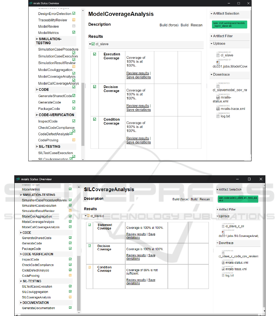
Figure 6: Model coverage results of battery slave controller via status report of the build tool ‘mrails’.
Figure 7: SIL coverage analysis result via status report of the build tool ‘mrails’.
4.4.1 Model Cyclomatic Complexity
Previously, the build tool did not have this model met-
ric calculation job integrated into the lifecycle pack-
age. In this research, a new verification job to get
the model metrics is added. This job is called by
the command mrails modelmetrics. The job basically
collects important model metric data like model cy-
clomatic complexity, parameter count, library count
and blocks count. These results are shows in the web
based HTML status report as shown in Figure 8. The
Simulink Metrics Dashboard can be opened via the
report. Metric data is created for each module and ag-
gregated result is also displayed. Aggregated cyclo-
matic complexity value of the slave controller module
is 8 which is acceptable.
MODELSWARD 2023 - 11th International Conference on Model-Based Software and Systems Engineering
190
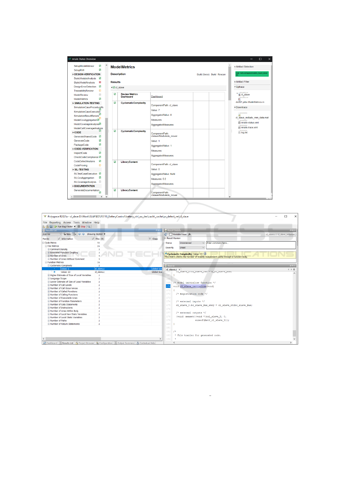
Figure 8: Model metrics results displayed on status report of the build tool ‘mrails’.
Figure 9: Polyspace Bug Finder result showing cyclomatic complexity of the battery slave controller.
4.4.2 Code Cyclomatic Complexity
The code cyclomatic complexity is calculated by
Polyspace Bug Finder tool. The tool provides sev-
eral other code metrics related to project, function and
file (Polyspace, 2022a). The build tool provides a job
called ‘code defect analysis’ which runs Polyspace
Bug Finder with required project settings. The re-
sults are accumulated in the designated location of
current project directory and are accessible via the in-
teractive web-based HTML status report of the build
tool. Figure 9 shows Polyspace cyclomatic complex-
ity result. It is found that the code cyclomatic com-
plexity for ‘cl slave’ is 13 which is higher than the
model cyclomatic complexity (8). Model and code
cyclomatic complexity can vary due to the additional
Application of a Process-Oriented Build Tool for Verification and Validation of a Battery Slave Controller for a Battery Modular Multilevel
Management System Along the DO-178C/DO-331 Process
191

error checks or logic introduced by the code genera-
tor. In our example, the code cyclomatic complexity
is high because of ‘for-loop’ in the code for vector in-
puts of multi-port switch and vector input ‘config’ of
the bus creator ‘bc slaveout Bus’. Static model cyclo-
matic complexity did not consider the signal dimen-
sions and hence the value was less.
5 FUTURE WORK
As a part of further verification of the slave controller,
processor-in-the-loop and hardware-in-the-loop tests
will be executed to also ensure the real-time function-
ality of the software. The next step is to develop and
verify the master controller in same aspects using the
build tool. As a part of this project, a motor con-
troller will also be developed and verified using the
build tool. The motor controller will give input to the
battery master controller with required voltage. Con-
tinuous Integration platform for all sub projects is also
being setup.
As mentioned before, the build tool is also be-
ing improved in parallel. Recent and future improve-
ments include fixing bugs, resolving issues faced by
developers, setup of Continuous Integration server for
development of the tool and also for its applications,
parallel modular code generation, etc.
6 CONCLUSION
In this research, a process-oriented build tool is ap-
plied to develop and verify a battery slave controller
for multilevel battery system. Following advantages
of the build tool are realized: traceability and aggre-
gation of verification results, incremental verification
tasks, predefined configuration settings of the verifi-
cation tools like Simulink test, Polyspace, SL cover-
age, etc., and interlinking of tools. To validate these
advantages, model and code coverage is discussed
explicitly in this paper. Significance of model and
code coverage with respect to DO-178C objectives
is clearly explained with brief description of the two
type of coverage: 1) Requirements-based coverage
analysis and 2) Structural coverage. Following the
description, these model and code coverage results of
slave controller application is discussed. Cyclomatic
complexity of model and code is discussed. A new
design job is also added into the lifecycle package of
the process-oriented build tool called as ‘Model Met-
rics’. This job provides the cyclomatic complexity
metric of the design models along with other com-
plexity metrics like library count, Simulink library,
parameter and block count, etc.
The future of this research consists of improve-
ment of the build tool itself and widening the applica-
tion areas of it. The build tool will be used to develop
a master battery controller and a motor controller in
this project.
This research is funded by ELAPSED as part of
dtec.bw - Digitization and Technology Research Cen-
ter of the Bundeswehr which we gratefully acknowl-
edge. (DTEC, 2021).
REFERENCES
Bavertis (2022). www.bavertis.com.
Bingol, M. K., Deniz, E., Sari, M., Saritas, I. E., and Yil-
mazer, Y. (2014). Adapting DO-178c processes by im-
plementing a reverse engineering technique. In 2014
33rd Digital Avionics Systems Conference. IEEE.
Brauer, J., Dahlweid, M., and Peleska, J. (2015). Tool-
supported structural coverage analysis for DO-178c
compliant software. In SAE Technical Paper Series.
Cleland-Huang, J., Agrawal, A., Vierhauser, M., and Mayr-
Dorn, C. (2021). Breaking the deep freeze. IEEE
Software, 38(3):43–51.
Dmitriev, K., Zafar, S. A., Schmiechen, K., Lai, Y., Saleab,
M., Nagarajan, P., Dollinger, D., Hochstrasser, M.,
Holzapfel, F., and Myschik, S. (2020). A lean and
highly-automated model-based software development
process based on do-178c/do-331. In AIAA/IEEE 39th
Digital Avionics Systems Conference.
DTEC (2021). Electric Aircraft Propulsion – die zukunft
der flugzeugantriebe. Accessed: 2022-04-11.
GrammaTech (2022). White paper: Making safety-
critical software development affordable with
static analysis. https://codesonar.grammatech.com/
making-software-affordable-with-static-analysis.
Hochstrasser, M., Myschik, S., and Holzapfel, F. (2018). A
process-oriented build tool for safety-critical model-
based software development. In Proceedings of the
6th International Conference on Model-Driven Engi-
neering and Software Development.
Hochstrasser, M., Myschik, S., and Holzapfel, F. (2019).
Application of a process-oriented build tool for flight
controller development along a DO-178c/DO-331
process. In Communications in Computer and Infor-
mation Science.
Hochstrasser, M. T. (2020). Modular model-based develop-
ment of safety-critical flight control software. Disser-
tation, Technische Universit
¨
at M
¨
unchen, M
¨
unchen.
Kersten, A., Kuder, M., Grunditz, E., Geng, Z., Wikner, E.,
Thiringer, T., Weyh, T., and Eckerle, R. (2019). In-
verter and battery drive cycle efficiency comparisons
of chb and mmsp traction inverters for electric vehi-
cles. In 2019 21st European Conference on Power
Electronics and Applications, pages P.1–P.12.
Kuder, M., Schneider, J., Kersten, A., Thiringer, T., Eck-
erle, R., and Weyh, T. (2020). Battery modular mul-
MODELSWARD 2023 - 11th International Conference on Model-Based Software and Systems Engineering
192

tilevel management (bm3) converter applied at bat-
tery cell level for electric vehicles and energy storages.
In International Exhibition and Conference for Power
Electronics, pages 1–8.
Macola, I. G. (2021). Ethiopian Airlines crash:
what’s happened in the last two years?
https://www.airport-technology.com/analysis/
ethiopian-airlines-crash-what-happened-last-two-years/.
[Accessed 25-Oct-2022].
Mamiit, A. (2015). Toyota recalls 112,500 vehicles due
to power steering and software issues. https://www.
techtimes.com/articles/39149/20150312/. [Accessed
25-Oct-2022].
MathWorks (2022a). Compare Model Com-
plexity and Code Complexity Metrics.
https://www.mathworks.com/help/slcheck/ug/
compare-model-complexity-and-code-complexity.
html. [Accessed 28-Oct-2022].
MathWorks (2022b). Cyclomatic Complexity — math-
works.com. https://www.mathworks.com/discovery/
cyclomatic-complexity.html. [Accessed 28-Oct-
2022].
MathWorks (2022c). Model Metrics - MATLAB ; Simulink
— mathworks.com. https://www.mathworks.com/
help/slcheck/ref/model-metric-checks.html. [Ac-
cessed 28-Oct-2022].
MathWorks (2022d). Simulink Coverage — math-
works.com. https://www.mathworks.com/products/
simulink-coverage.html. [Accessed 28-Oct-2022].
McCabe, T. (1976). A complexity measure. IEEE Transac-
tions on Software Engineering, SE-2(4):308–320.
Olszewska, M., Dajsuren, Y., Altinger, H., Serebrenik, A.,
Wald
´
en, M., and van den Brand, M. G. J. (2016). Tai-
loring complexity metrics for simulink models. In
Proccedings of the 10th European Conference on Soft-
ware Architecture Workshops. ACM.
Panchal, P., Myschik, S., Dmitriev, K., Bhardwaj, P., and
Holzapfe, F. (2022a). Handling complex system archi-
tectures with a do-178c/do-331 process-oriented build
too. In 2022 IEEE/AIAA 41st Digital Avionics Systems
Conference.
Panchal, P., Myschik, S., Dmitriev, K., and Holzapfel, F.
(2022b). Application of a process-oriented build tool
to an INDI-based flight control algorithm. In AIAA
AVIATION 2022 Forum. American Institute of Aero-
nautics and Astronautics.
Panchal, P., Sorokina, N., Myschik, S., Dmitriev, K., and
Holzapfel, F. (2022c). Application of a process-
oriented build tool to the development of a bm3 slave
controller software module. In DLRK.
Polyspace (2022a). MathWorks Account Sign In —
mathworks.com. https://www.mathworks.com/help/
bugfinder/ug/review-code-metrics.html. [Accessed
28-Oct-2022].
Polyspace (2022b). Polyspace Bug Finder — math-
works.com. https://www.mathworks.com/products/
polyspace-bug-finder.html. [Accessed 28-Oct-2022].
Rapita (2022). White paper: Eight top code coverage ques-
tions for do-178b/c. https://www.rapitasystems.com/
downloads#whitepapers.
Rierson, L. (2017). Developing Safety-Critical Software: A
Practical Guide for Aviation Software and DO-178C
Compliance. CRC Press.
RTCA (2011a). DO-178C Software Considerations in Air-
borne Systems and Equipment Certification. Standard,
RTCA.
RTCA (2011b). DO-331 Model-Based Development and
Verification Supplement to DO-178C and DO-278A.
Standard, RTCA.
Siemens (2004). (ALM), Requirements Management,
QA Management — Polarion - Software — po-
larion.plm.automation.siemens.com. https://polarion.
plm.automation.siemens.com/. [Accessed 28-Oct-
2022].
Sun, Y., Brain, M., Kroening, D., Hawthorn, A., Wilson, T.,
Schanda, F., Jimenez, F. J. G., Daniel, S., Bryan, C.,
and Broster, I. (2017). Functional requirements-based
automated testing for avionics.
TUM (2018). SimPol — TUM; Institute of Flight Sys-
tem Dynamics; Software — fsd.lrg.tum.de. https://
www.fsd.lrg.tum.de/software/simpol/. [Accessed 28-
Oct-2022].
Watson, A., Wallace, D., McCabe, T., Associates, M. .,
of Standards, N. I., and (U.S.), T. (1996). Structured
Testing: A Testing Methodology Using the Cyclomatic
Complexity Metric. NIST. U.S. National Institute of
Standards and Technology.
Yinghui, L., Yuerang, Z., Xiaojun, H., Yan, S., and Yu, B.
(2011). Coverage analysis of airborne software testing
based on DO-178b standard. Procedia Engineering,
17:480–488.
Application of a Process-Oriented Build Tool for Verification and Validation of a Battery Slave Controller for a Battery Modular Multilevel
Management System Along the DO-178C/DO-331 Process
193
