
Towards a Fleet of Autonomous Haul-Dump Vehicles in Hybrid Mines
Alexander Ferrein
a
, Michael Reke
b
, Ingrid Scholl, Benjamin Decker, Nicolas Limpert,
Gjorgji Nikolovski
c
, and Stefan Schiffer
d
Mobile Autonomous Systems and Cognitive Robotics Institute (MASCOR),
FH Aachen University of Applied Sciences, Aachen, Germany
Keywords:
Automation, Mining, Control, Autonomous Fleet, Object Detection, Planning, Robotics, Semantic Mapping.
Abstract:
Like many industries, the mining industry is facing major transformations towards more sustainable and de-
carbonised operations with smaller environmental footprints. Even though the mining industry, in general, is
quite conservative, key drivers for future developments are digitalisation and automation. Another direction
forward is to mine deeper and reduce the mine footprint at the surface. This leads to so-called hybrid mines,
where part of the operation is open pit, and part of the mining takes place underground. In this paper, we
present our approach to running a fleet of autonomous hauling vehicles suitable for hybrid mining operations.
We present a ROS 2-based architecture for running the vehicles. The fleet of currently three vehicles is con-
trolled by a SHOP3-based planner which dispatches missions to the vehicles. The basic actions of the vehicles
are realised as behaviour trees in ROS 2. We used a deep learning network for detection and classification
of mining objects trained with a mixing of synthetic and real world training images. In a life-long mapping
approach, we define lanelets and show their integration into HD maps. We demonstrate a proof-of-concept of
the vehicles in operation in simulation and in real-world experiments in a gravel pit.
1 INTRODUCTION
In the future, the European raw materials industry will
undergo an increasing change from open pit mining
to underground mining. Digitalisation and automa-
tion are keys for further transforming mining oper-
ations into a decarbonised and more sustainable op-
erations (see, e.g. (Batterham, 2017; Sánchez and
Hartlieb, 2020; Clausen and Sörensen, 2022)). This
transition usually requires big investment on the part
of the operator to upgrade the entire infrastructure
(e.g. crusher and conveyor system) from surface to
underground. The requirement to lower the surface
footprint means that the mining operation will go un-
derground. This leads to hybrid mining operations,
where parts of the mine are still open pit and parts are
underground mines. Already today, especially in the
stone and earth industry, some raw materials mining
companies are already using a hybrid mode of oper-
ation and are deploying their machinery both under
and above ground.
a
https://orcid.org/0000-0002-0643-5422
b
https://orcid.org/0000-0002-4209-8574
c
https://orcid.org/0000-0002-6009-8148
d
https://orcid.org/0000-0003-1343-7140
An autonomous system, suitable for both under-
ground and surface operation, would be able to carry
out transport and unloading processes around the
clock under the most difficult conditions. This also
enables a continuous production process, while in-
juries could be significantly reduced. Accordingly,
mining companies are increasingly seeking to use au-
tonomous machines (see, e.g. (Petty, 2017)) for the
extraction of raw materials. Autonomous machinery
embeds intelligence into mining machines so that they
are more efficient, self-correcting, safer, and more
connected. Especially in times of skilled labor short-
ages, this can also free up personnel from everyday
tasks. They can, hence, focus on observing the sys-
tem as a whole.
Autonomous mining machines offer three key
benefits: (1) Machines can be deployed with longer
daily working hours; (2) they continuously deliver
consistent results, regardless of time, to increase ef-
ficiency and productivity while also improving safety
of employees if operating in a 24/7 mode; (3) through
the use of an autonomous fleet and a system-wide
and even cross-system optimization, the economic ef-
ficiency of raw material extraction will be increased,
accident rates can be reduced and a continuous pro-
278
Ferrein, A., Reke, M., Scholl, I., Decker, B., Limpert, N., Nikolovski, G. and Schiffer, S.
Towards a Fleet of Autonomous Haul-Dump Vehicles in Hybrid Mines.
DOI: 10.5220/0011693600003393
In Proceedings of the 15th International Conference on Agents and Artificial Intelligence (ICAART 2023) - Volume 1, pages 278-288
ISBN: 978-989-758-623-1; ISSN: 2184-433X
Copyright
c
2023 by SCITEPRESS – Science and Technology Publications, Lda. Under CC license (CC BY-NC-ND 4.0)

duction process around the clock can be implemented.
In this paper we report on our steps towards these
goals. Continuing our efforts of automating mine op-
erations in a previous project on site exploration and
mapping (Ferrein et al., 2019; Donner et al., 2019),
we here present the ongoing work on a fleet of three
dumper vehicles suitable for autonomous hauling op-
erations in hybrid mines.
The contribution is threefold. First, we cre-
ated and realized a vehicle setup that allows for au-
tonomous operation and we established a software
architecture for the vehicle based on version two
of the Robot Operating System (ROS) (Reke et al.,
2020)(Macenski et al., 2022). Second, we developed
and integrated a high-level control component for the
vehicles as well as an overall fleet management sys-
tem. This includes coordination planning for multi-
vehicle situations. Third, we integrate semantic 3D
mapping and a life-long mapping approach to contin-
uously monitor the environment and update the sys-
tem’s representation accordingly.
2 BACKGROUND AND RELATED
WORK
Compared to autonomously driving road vehicles and
autonomously acting robotic vehicles, autonomous
dump trucks are an application that is right in between
in several ways. The differences lie in the following:
• speed: With a maximum speed of dump trucks in
the range of 20-30 km/h, the application is signif-
icantly higher than robotic vehicles but also still
well below the maximum speed of road traffic.
• routes: In the area of surface and underground
mines, traffic mostly takes place on defined
paths. However, these paths cannot be compared
with a well-developed and sign-posted road net-
work. The paths are also not completely arbitrary,
though, as it is the case with many robotic vehi-
cles.
• vehicles: Although the vehicles have an Ack-
ermann 4-wheel kinematics (Delrobaei and
McIsaac, 2011), they are still special because they
have articulated steering. Robotic vehicles, on the
other hand, many times are able to turn on the
spot. This is because they mostly feature direct
electric drives, and no gear ratios need to be cho-
sen and stepless switching between forward and
reverse is possible.
For the design and realization of the hardware and
software architecture for the vehicles we face mixed
implications. Due to the similarities in approaches
for road vehicles and robot vehicles, some ideas can
be adopted. However, due to the differences in many
areas other solutions and extensions to existing tech-
nology have to be found.
Irrespective of the current standardization efforts
of the industry, ROS is often used in the development
of control systems for autonomous driving vehicles
(cf. e.g. (Aeberhard, 2015)). The reason for this is,
on the one hand, the flexible architecture, in which
it is possible to compute many functions in parallel
nodes and on the other hand the availability of help-
ful development tools like RViz for visualization or
different simulators. Particularly promising for au-
tonomous driving are the new functions provided by
ROS 2
1
offers, such as the real-time communication
via DDS and a real-time capable multithreading de-
sign. In the field of self-driving car software, some
systems have already been ported to ROS 2. Exam-
ples are Apollo
2
and Autoware
3
. In our own previ-
ous work, we also proposed a ROS 2-based system
architecture for self-driving cars (Reke et al., 2020).
Life-long mapping approaches aim to detect dynamic
changes in the environment and adapt local environ-
ment maps to these changes. For this purpose, seman-
tically enriched maps have been successfully used
in robotics, both indoors and outdoors (Lang et al.,
2014). Semantic object recognition and classification
is usually acquired continuously in time using convo-
lutional neural networks (Qi et al., 2017). With simul-
taneous localization and mapping approaches (Tipaldi
et al., 2013), the detected object and localization data
can be registered and integrated with the environment
map (Rosen et al., 2016).
3 VEHICLE SETUP AND
SOFTWARE ARCHITECTURE
The software architecture we present is an adaptable
model-based specification we use on multiple auto-
mated vehicles. It is based on an architecture de-
sign which has been used for self-driving vehicles
with Ackermann steering proposed in our previous
work (Reke et al., 2020). As the architecture does
not make specific assumptions about the vehicle type,
it was particularly easy to adopt the software archi-
tecture to the articulated dump vehicles used in this
work.
1
https://design.ROS2.org/. For an overview on the
ROS 2 performance also see (Maruyama et al., 2016).
2
https://www.apollo.auto/
3
https://www.autoware.auto/
Towards a Fleet of Autonomous Haul-Dump Vehicles in Hybrid Mines
279
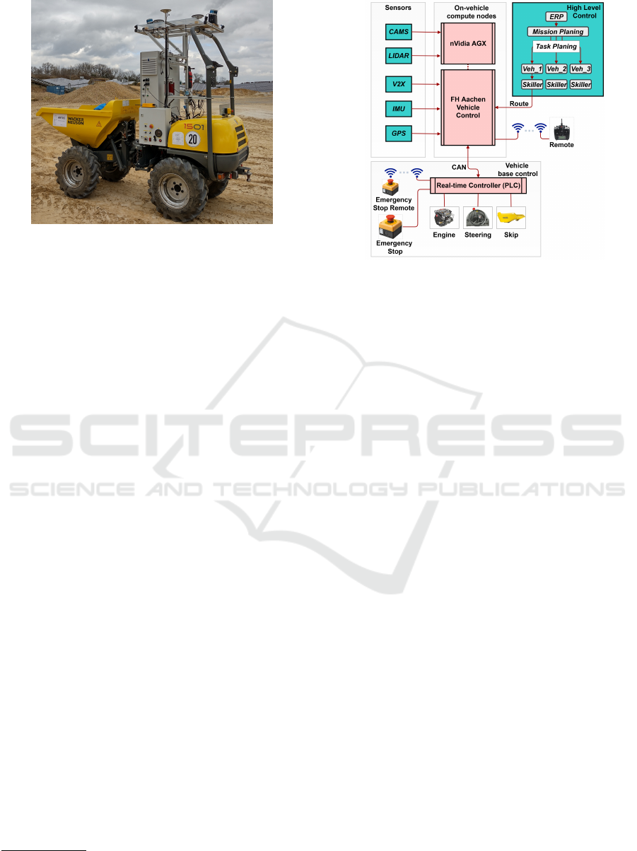
Figure 1: Picture of one of the articulated haul-dumpers at
the test site.
3.1 Hardware
The base vehicle we use is an articulated haul-dumper
by the company Wacker Neuson (Model 1501).
4
Our
fleet consists of three of those vehicles. Figure 1
shows an examplary prototype. The model we se-
lected is designed for smaller loads of only 1.5 tons.
It is human-operated through a steering wheel, ped-
als for the brake and throttle and levers to control the
skip movement. The control of the brakes and the an-
gle of the articulated joint of the vehicle is realized by
a hydraulic system, which depends on the hydraulic
pressure generated by a diesel engine. To automate
the vehicle, we have installed electric linear actuators
to control the brake and the throttle. Additionally we
attached a rotational servo-motor to the steering-axis
and the manual valves by electromagnetic valves to
control the skip. We also installed hall-sensors on
each wheel to obtain information on the vehicle state.
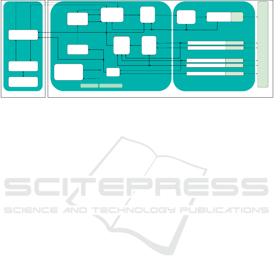
The control system is subdivided into different
hardware components as can be seen in Figure 2.
These parts are presented in the following.
Real-Time Controller. The control unit we use in
the vehicle to process the signals to control the elec-
tric motors and the feedback signals from installed
sensors, is a programmable logic controller (PLC) by
Beckhoff. To transfer information to and from the
PLC we utilise CAN. The PLC serves as a message
filter, that prevents unsafe commands to be propa-
gated to the motors, and kill-switch manager. For
safety there are multiple kill-switches on the vehi-
cle as well as one radio kill-switch. In addition the
PLC serves as a PID-controller regulating the angle
of the articulated joint and the engine speed by prop-
erly actuating the motor moving the steering axis and
4
https://www.wackerneuson.de/produkte/dumper/
raddumper/raddumper-1501/
Figure 2: System architecture of haul-dumper control sys-
tem.
the motor opening and closing the throttle valve. For
more detail, we refer to (Sürken, 2021).
Compute Nodes. As described below, we use a
CUDA-based model-predictive path-follower as well
as high level control and computer vision algorithms.
These algorithms run on two dedicated compute de-
vices. We make use of a Zotac ZBOX Magnus One
to run the path-follower, high-level control, and se-
mantic and life-long mapping algorithms. In addition,
we deploy an Nvidia Drive AGX Xavier that runs the
computer vision tasks. The AGX interfaces directly
with high-bandwidth sensors such as the cameras and
directly processes them. Both compute devices run a
linux-based operating system with no modifications
to obtain deterministic time execution of the tasks
running on the devices.
Sensors. Our main localization hardware is an
OxTS RT3000v3 dGPS on one unit and two OxTS
xNav650 on the remaining two units. Each dGPS con-
tains an inertial measurement unit. As vision sensors
we utilise two VLP-16 Lidars and six cameras using
gigabit multimedia serial link transport (abbreviated
to GMSL cameras).
3.2 Software Architecture
Our software architecture features a modular design
(Reke et al., 2020) separating the task of automa-
tion into encapsulated nodes that each solve a specific
problem. The software components communicate
with each other where appropriate based on ROS 2
publisher / subscriber communication along with ser-
vices. Figure 3 shows an overview of our architecture.
We use concepts and approaches of other projects
commonly used in ROS such as Navigation2 (Macen-
ICAART 2023 - 15th International Conference on Agents and Artificial Intelligence
280
Vehicle-unspecific
Behaviour
Planning
(BehaviourTree,
Monitoring)
Vehicle & Sensor-specific
Coordinator
(NodesStates
Monitoring, Lifecycle
Management)
Global Route
Planning
(Lanelet2 /
Smac)
CAM (Driver, Detection) HW - Driver
Object Lists (dynamic, free space)
Object Lists (dynamic)
Global
path
MAP/HD-MAP Node Parameters Data:
Dumper
High Level Control
Goal
Maneuver
List
global
path
Node
transition
(every Node)
SHOP Planer
(Fleet Management)
RVIZ Visualisation
Lanelet / Position /
Obstacles
Action
Node status
(every Node)
Status
Base Station
Dumper 1 .. X
Pose
Path
Control
(MPC)
velocity
control
Localization
(UKF
Global)
ROS2Dumper
Vehicle
Control
(Veh.)
ROS2Dumper
Vehicle Interface
(Veh.)
HW -
Driver
Wheelencoder (Odom)
Lidar (Environment detection)
GPS (Driver)
IMU (Driver)
HW - Driver
HW - Driver
Vehicle
CMDs
Actual steering
angle, speed
Target
steering
angle,
speed
filtered
Pose
GPS Data
IMU Data
HW - Driver
HW - Driver
Localization
(UKF Local)
filt.
global
Position
Goal
Action
Feedback
Actual steering
angle, speed
Object
List
Live-Long-
Mapping
map
updates
Objects/Obstacle
Pose
Odometry
IMU Data
Figure 3: Diagram of the software architecture.
ski et al., 2020) and robot_localization (Moore and
Stouch, 2014).
Centralized Mission Management Block. At the
top-most level in the hierarchy of decision making
and control of the fleet is the high-level control block.
Given a daily goal defined by the operator the high-
level task is to generate plans consisting of hierarchi-
cally ordered actions. The action plans are generated
using SHOP3 (Goldman and Kuter, 2019). The fleet
manager module then takes care of dispatching the ac-
tions in the plans rendered by SHOP 3. During exe-
cution a world model is updated given the positions
of the trucks and their currently locked resources, the
status of the excavators and how much tonnage has
been hauled. In case major discrepancies to the previ-
ous plan occur a re-planning is initiated.
Vehicle Unspecific Block.
The separation of concerns into local and global
localization is inspired by the implementation of
robot-localization (Moore and Stouch, 2014). The
global localization filters signals of sensors deliver-
ing predominantly discrete information on the posi-
tion of the vehicle in a global coordinate frame such
as the Universal Transverse Mercator (UTM). In con-
trast, the local localization filters mostly signals from
sensors delivering continuous differential information
on the vehicle, which can be then integrated to esti-
mate the state of the vehicle. The global route plan-
ner is either a free-space planner or an HD-Map-based
planner that generates paths, that the path-follower
has to follow. The path-follower is a controller, that
keeps the vehicle on track of the global route and
gives feedback on the success of following the given
path. (Pivtoraiko et al., 2007; Limpert et al., 2015)
As path-follower we use a model-predictive controller
which uses a CUDA-based grid-search on a set of
predicted trajectories achievable by the vehicles kine-
matic model. It is a modified version of the model-
predictive control (MPC) presented by (Chajan et al.,
2021). The behaviour planning module coordinates
the execution of tasks prescribed by the fleet (or mis-
sion) management.
The life-long mapping module consists of soft-
ware that updates the map which is used as basis for
the global route-planner to crate routes. In our case
the maps used for navigation consist of HD-maps in
the Lanelet2 format (Poggenhans et al., 2018a).
Vehicle Specific Block. The vehicle specific
block mostly consists of drivers and vehicle commu-
nication modules.
The drivers are for cameras, inertial measurement
units (IMUs), GPS-units, LiDARs and Wheel en-
coders. It is essential to notice, that vision systems
such as cameras or LiDARs should implement detec-
tion closely coupled to the driver. The fusion of de-
tected objects is optional according to our architecture
design, but if fused, a late-fusion approach is the pre-
ferred method. We have implemented an object detec-
tion with cameras using YOLOv5 to aid in the seman-
tic and life-long mapping. We also implemented a
modular way of integrating state-of-the-art deep neu-
ral networks for 3D object detection in point-clouds.
The detailed presentation of the latter is part of previ-
ous work presented in (Nikolovski et al., 2021).
All modules in both the vehicle-specific and un-
specific blocks run on each vehicle in the fleet.
Currently, the architecture is implemented using the
ROS 2 middleware. Communication between the
modules and the centralized high-level control is pro-
vided by Cyclone DDS on a shared network.
Towards a Fleet of Autonomous Haul-Dump Vehicles in Hybrid Mines
281

4 HIGH-LEVEL CONTROL AND
FLEET MANAGEMENT
A common scenario at the mission level for open pit
or underground mining activities is that the ore is be-
ing mined at some mining face and it is then being
loaded by an excavator to a hauling vehicle. This
vehicle transports the material to a so-called crusher
which further grinds the material. So, for coordinat-
ing a fleet of autonomous hauling vehicles the typi-
cal actions are: drive to the excavator, load the mate-
rial, drive to the crusher and unload. For controlling
our hauling vehicles, we deployed the SHOP 3 plan-
ner (Goldman and Kuter, 2019). With this planner, a
day-plan was created taking into account the respec-
tive resources contraints such as number of availabe
vehicles, tonnages etc. The sub-tasks were communi-
cated to the different vehicles as ROS 2 actions. Each
action was implemented as a behaviour tree in ROS 2.
In addition, we make use of a separate lock-broker to
manage the locking of resources.
4.1 World Model
The system features a world model that is continu-
ously updated. It consists of the environmental re-
sources and the total tonnage to be hauled and it
is used as the problem definition to be used with
SHOP 3. The resources comprise of the trucks
and excavators with their activity level, the positions
along with path segments that are either occupied or
traversable. The latter is later used for navigation pur-
poses for egocentric path planning within multiple ve-
hicles. To represent the path segments as static re-
sources within the world model and traversable parts
we use Lanelet2 (Poggenhans et al., 2018b). The nav-
igation graph in Lanelet2 represents discrete lanelets
consisting of global navigation system (GNS) posi-
tions. We focus on the plain paths and area represen-
tations with no further traffic rules or velocity lim-
itations. A lanelet is considered a resource that is
either occupied or traversable. The area representa-
tion of Lanelet2 is used to provide lockable resources
to the planning system. Examples are areas that are
maintained by an excavator which then should only be
used by one truck at the same time for safety reasons.
The identifications of lanelets are used as discrete re-
sources which are only to be used by one truck at the
same time. The excavators are considered to stay at
one position during the shift that is considered to be
the time window of the planning.
4.2 High-Level Task Planning with
Behavior Trees
The tasks to fulfill from the high-level planning per-
spective require abstraction of the actions that the
platform can perform. The high-level planning should
be able to send actions which do not take low-level
properties of the vehicle into account (such as lat-
eral acceleration). Therefore the high-level planning
has the following actions defined in the domain de-
scription: DRIVE - Bring the vehicle to a desired goal
lanelet; LOAD - Issue a loading action close to an ex-
cavator; UNLOAD - Unload the material into a crusher;
QUEUING - Wait at the current position for a certain
amount of time. The plan generated by the SHOP 3
planner is read by the dispatcher which keeps track
of the actions dispatched to the vehicles. During the
execution the dispatcher receives feedback from the
executing ROS node that hosts the action server. This
also gives the opportunity to decide to cancel the run-
ning action. On the vehicle side the action servers
consist of behavior trees following encapsulated be-
haviors in order to fulfill the respective action. A
prominent example is the DRIVE action as defined in a
behavior tree which, from a conceptual point of view
adheres to the following scheme:
1. Compute a route to the desired goal lanelet given
the Lanelet2 library and the static map defining
the environment
2. In case a route was successfully found forward
this path to our model predictive controller to fol-
low the path
3. Finalize the motion once the goal is reached
4. During the motion the velocity commands are val-
idated for lead to collision free motion. In case
a collision would occur the MPC is instructed to
stop and the DRIVE action is considered to fail
The DRIVE behaviour also includes a locking mecha-
nism for path segments (junctions, one way roads).
A resource broker is in charge for overseeing the
locks and giving permissions to cross path segments.
For more information on this, we refer to (Mühlens,
2021).
Static routes do not cover navigation with dy-
namic obstacles. For local obstacle passing we fol-
low an alternative route planning method which takes
local obstacles into account. The strategy of the be-
havior tree is to find a follow-up point that leads back
to the static route. Ideally, the LOAD action issues
the truck to end up being fully loaded and ready for
the next DRIVE actions regularly followed by UNLOAD.
Similar to the local resource handling to pass junc-
tions, the LOAD and UNLOAD actions require proper
ICAART 2023 - 15th International Conference on Agents and Artificial Intelligence
282
negotiation between the trucks and the excavator or
crusher. Controlled by queues, trucks have to be
loaded one after another in case of multiple trucks
queuing at the loading point. The loading queue is
controlled by the excavator which instructs the trucks
to move from their queuing position to either the next
point in queue or to the final loading pose. The
UNLOAD action behaves similarly - given the fact that
a crusher point can usually only be used by one truck
at a time.
4.3 Fleet Level Planning with SHOP3
Individual mining sites require custom optimization
criteria from the planning perspective and the scope
of the remaining time of the current shift. In some
cases a meaningful heuristic is to aim for minimizing
the waiting time of trucks or excavators while other
situations require the minimization of the cycle time
or the shovel saturation. With the world model known
a priori, trucks, excavators, and crushers along with a
routing graph are coordinated to respect optimization
criteria. In its original form, SHOP 3 does not support
planning with temporal aspects. To overcome this, we
added times as additional properties.
4.4 Machine-to-Machine Resource
Locking
The characteristics of large open cast and under-
ground mining sites prevent reliable global communi-
cation between all participating entities. The systems
thus have to be able to locally negotiate with each
other in order to execute the action. Instead of coordi-
nating the orders in which vehicles pass junctions the
global fleet management has to coordinate the global
environment. Lanelet segments being resources can
therefore also be used to queue up vehicles along the
way by considering that each lanelet segment can only
be occupied by one vehicle at a time. As a result,
basic physical computing instances host the queues
required to lock and unlock the respective resources
close to the actual resource (i.e. lanelet segments).
5 SEMANTIC AND LIFE-LONG
MAPPING
The semantic and life-long mapping in our project
consists of four parts: the object detection and clas-
sification of static and dynamic objects, the localiza-
tion of static objects in a global coordinate system,
and the (continuous) integration of these information
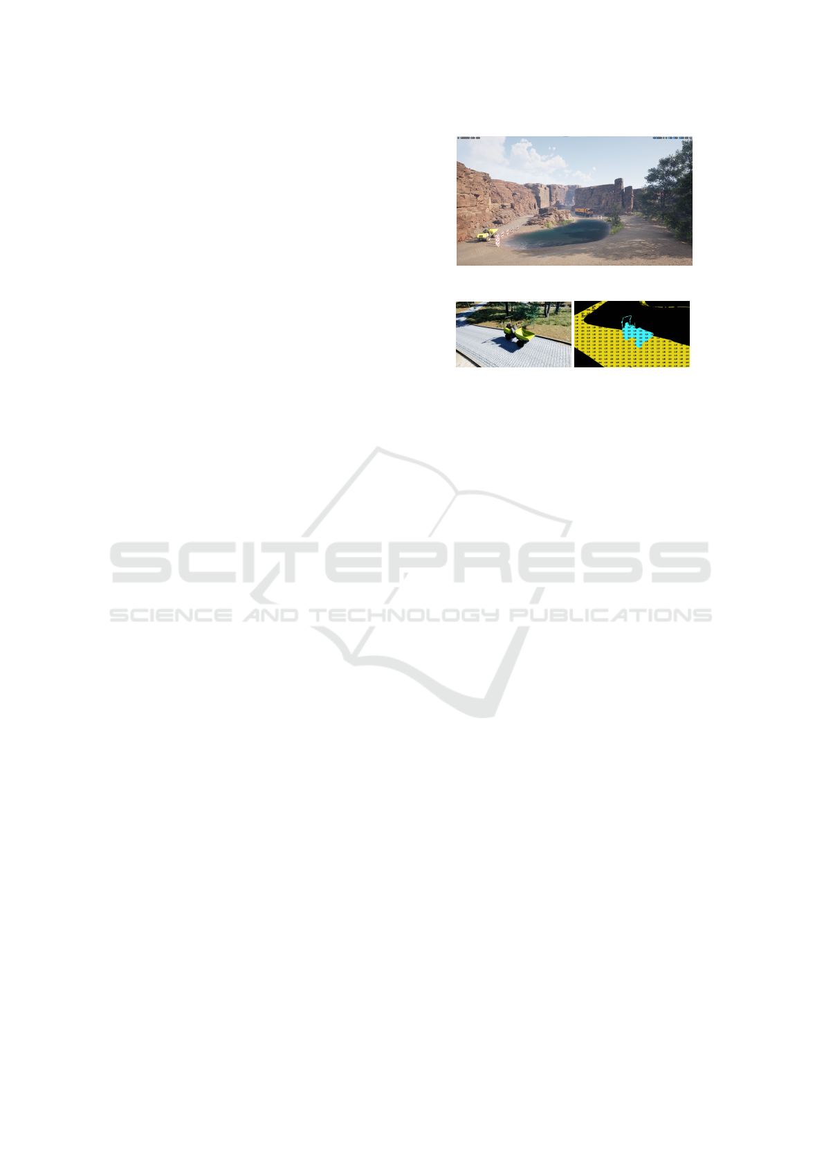
(a) Virtual reality world with relevant 3D mod-
els.
(b) Simulated image. (c) Labeled image.
Figure 4: Virtual reality world with 3D models created with
Unreal Engine 5 to get annotated training data from simu-
lated driving.
into an HD-Map. The following sections explain the
four parts in more detail.
5.1 Object Detection
For object recognition, the deep learning network
YOLOv5 was used to recognize people, beacons for
lane marking, and other vehicles in the mining envi-
ronment. To recognize new objects with the YOLOv5
network, a three-stage training approach was devel-
oped:
1. Creating Synthetic Training Data Set:
Deep Learning networks require millions of pre-
annotated images to recognize objects. To an-
notate all these images manually, especially of
new objects in new environments, is a very time-
consuming and expensive process. To automate
this process, a similar environment to the mining
world, the dumper as well as the beacons were
modeled in 3D and with these models a virtual
world as realistic as possible was created as a sim-
ulation environment using Unreal Engine 5 and
can be seen in Figure 4a. In addition, virtual
cameras from the first-person perspective of the
dumper were integrated into the virtual reality en-
vironment. Through animated virtual driving of
the dumpers, the virtual camera images along with
their annotation can be saved to the hard disk as
annotated data sets, see Figures 4b and 4c. These
annotated image data are the synthetic training
data set for the YOLOv5 network.
2. Image Augmentation Tool:
One problem with synthetically generated data for
Towards a Fleet of Autonomous Haul-Dump Vehicles in Hybrid Mines
283
neural network training is its purity. This means
that the synthetic training images taken in the vir-
tual world should not have any impurities such
as noise or blur. One solution is to subsequently
incorporate these variations into the training im-
ages. For this purpose, we have developed an
image augmentation tool that uses varying pa-
rameters to add noise and modify lighting, sat-
uration, image resolution, and horizontal image
alignment. Using this technique, the synthetic
training data becomes more realistic.
3. Training Data From Real Driving Scenarios:
Image recordings from real drivings were man-
ually annotated and additionally varied with the
image augmentation tool. In this way, a multiple
of the manually annotated image data can be ob-
tained as training data from real image recordings.
The classifier is trained from mixing synthetic im-
ages with real images with 299 epochs of training,
reaching 0.9835 mAP@0.5 and 0.9836 mAP@0.95
based on YOLOv5m. The classifier also reliably de-
tects partially hidden objects. Deployment on the
Nvidia AGX Drive is achieved by converting the
trained classifier from PyTorch to ONNX and then to
TensorRT. The deployed classifier runs on the AGX
Drive with an inference time of about 35 milliseconds.
5.2 Lane Detection
We use the beacons as static objects defining the
boundaries of the navigable roads. With the classi-
fied bounding box we then estimate the 3D position of
the beacons by projecting the mid-point of the lower
bounding-box-boundary to a ground plane using the
extrinsic parameters of the cameras relative to the ve-
hicle center. At last, we obtain the world position of
the beacons by transforming the estimated, vehicle-
relative position into the UTM frame.
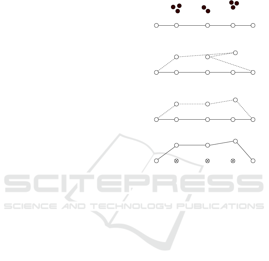
5.3 Boundary Matching and Map
Correction
To match the positions of the beacons to a lane
boundary we first filter the position-list created by
the object-detection. Initially, a binning filter down-
samples the positions by averaging the positions
which are close to each other. With this we can re-
duce the effects of measurement noise of the beacon
position. Then we pass the down-sampled through a
logical constraint filter which checks if the interpo-
lation of the new lane-boundary is feasible. After-
wards, we proceed with re-indexing the positions of
the beacons according the current lane boundary. The
(a) Initial state of the estimate for the beacon
positions (circles with infill) next to the lane
boundary points (circles without infill).
2
31
(b) State after filtering the positions of the bea-
cons. Dotted line denotes the proposition for
the new lane boundary at this point.
3
2
1
(c) State after re-indexing the beacon-position
groups.
3
2
1
(d) In the final stage old points of the lane
boundary are removed and the new lane bound-
ary is created.
Figure 5: State of the lane boundary at the four stages of the
lane boundary correction process.
order of positions is now determined by the medial
distance of each position from a beginning point of a
lane-boundary segment. The beginning point of the
lane boundary segment is the first point in the under-
lying geometric line structure of the lane boundary.
Accordingly the end point of a lane boundary seg-
ment is the last point in the underlying geometric line
structure of the lane boundary. The newly indexed list
of positions then replaces the list of points between
the beginning point and the ending point of the lane
boundary segment. The state of the lane boundary in
each step is depicted in Figure 5.
5.4 LiDAR Map to HD-Map
Our approach of generating an HD-map from a Li-
DAR map consists of six parts: segmenting the navi-
gable ground-segment from the point-cloud, calculat-
ing the concave hull of the navigable ground-segment,
calculating a Voronoi-graph for the concave hull, find-
ing the longest chain of vertices in the Voronoi-
graph (Bhattacharya and Gavrilova, 2007), smooth
the vertices of the chain to make the path-following
easier and convert trajectory described by the pro-
ICAART 2023 - 15th International Conference on Agents and Artificial Intelligence
284

cessed chain of vertices into a lane. In Figure 6 we
show a visualization of the result of each part. To
extract the ground-segment of the point-cloud map,
we first create an elevation map from the point-cloud
map. From the elevation map we sample a grid of
points uniformly from. We then filter the sample
points with an neighbor-elevation-difference heuris-
tic. If the difference of the elevation of a point to
its direct neighbors is to large, its remove from the
sampled points. It is similar to the implementation
of the simple-morphological filter from (Pingel et al.,
2013). Once the sampled points are filtered, we cal-
culate a two dimensional spanning-polygon by flat-
tening the points to the xy-Plane and estimating their
concave hull with alpha shapes. On the polygon we
apply a Delaunay-triangulation (Musin, 1997). We
then use the graph of the resulting Voronoi-diagram
to estimate the longest chains of vertices that passes
through each part of the point-cloud. After finding
the longest chains of vertices we apply a moving-
average to smooth out the vertices in sections where
the Delauney triangulation created local snaking pat-
tern. Then we take those vertices and form a lane of
fixed width around the path described by the vertices
in each chain.
6 EXPERIMENTAL RESULTS
In the following we present the results we created
throughout our research in terms of quantitative anal-
ysis of certain modules and qualitative observations
on a multi-module level.
Vehicle Automation. The hardware setup we use
has been reliable for the duration of our project.
Throughout our testing we have driven multiple hun-
dreds of hours and have yet to see critical failures
which compromise the whole system. The most com-
mon failure point is the supply of power to the com-
ponents on the vehicle. With the installed PLC and
the overall systems sluggishness due to the underly-
ing hydraulic mechanism, we observe mean 200 ms of
latency from sending a command to the actuators real-
izing the target values. We also observe latency when
using the emergency stops. The time to full stop af-
ter pressing an emergency switch is 1.5 seconds. The
path-following we implemented results in a 0.1 me-
ters mean lateral deviation from path on straight sec-
tions and 0.9 meters mean lateral deviation from path
in curves.
Fleet-Level Planning. We have tested the fleet level
planning in two ways. We have used rough simu-
lations to emulate the work process in a mine and
we have tested its integration to the lower modules
in the architecture. The integration test is described
later. For simulation we created 2 scenarios with dif-
ferent complexities. The first one consists of simple
goals and resources and the second simulates a hybrid
mine with multiple types of resources and outputs. In
each scenario we investigate 4 strategies minimizing
a different heuristic. Strategy one minimizes the idle-
time of all vehicles in a fleet. Strategy two minimizes
the average time a wheel-dumper needs to complete
a load and unload. The third strategy minimizes the
time the wheel-dumpers spend without moving loads.
The last strategy is selecting a plan from a set of ran-
domly generated plans that maximizes the haulage
mass. We simulated a period of 8 hours and observe
accumulation of idle-time and overall haulage mass.
The results can be found in Table 1.
Long-Term Mapping. The functional test we con-
duct to examine the results of our findings in live map-
correction is to manipulate the map manually and ob-
serve the reaction of for example the global route
planner and the vehicle itself. The most frequent sce-
nario tested in this regard is the manipulation of parts
of the lane leading up to the loading-station in the in-
tegration scenario depicted in Figure 7.
Integration Scenario. In an integration test sce-
nario we have unloading and loading stations to pick
up and unload payload. The unloading-heap can be
accessed at two locations while the loading-station is
accessible only from one location. There are two bidi-
rectional lanes leading up to the unloading-heaps ac-
cess locations and only one bidirectional lane leading
up to the loading-stations access location.
The day hauling schedule given to the fleet man-
agement is a sequence of repeated load-unload tasks
for both vehicles. The loading point on the right is
only accessible through one bidirectional lane. We
use this to our advantage to make the loading resource
scarce. It can be locked and occupied by one vehicle
only. The high-level control has to coordinate the ac-
cess of each resource so that no conflicts arise. The
locking of resources is managed by the mission plan-
ning. Each vehicle individually has to try to acquire
the lock on the resource. The first vehicle to reach
the fork in the middle of the traffic network, while
the loading resource is uncontested, receives the lock
on resource and with that blocks the lane leading up
to the resource. If the following vehicle, has to ac-
cess the locked resource it is required to wait until
the fleet management unlocks the resource. In an
eight hour operation it showed that the locking mech-
Towards a Fleet of Autonomous Haul-Dump Vehicles in Hybrid Mines
285
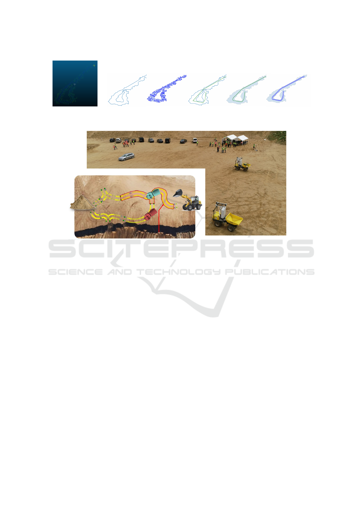
(a) (b) (c) (d) (e) (f)
Figure 6: Processed point-cloud map after each step of the conversion from point-cloud map to HD-map.
Presenta�on at Demonstra�on Day
Integra�on Scenario
Unloading
heap
loader
sta�on
Bidirec�onal
lane locked by
one vehicle
Figure 7: Visualization of the integration scenario, which were presented at a demonstration day.
anism works robustly and the day plan could be im-
plemented by the vehicle fleet.
7 CONCLUSION
Addressing the challenges of hauling in a hybrid un-
derground and open pit mine, we realised a fleet of
three wheel-dumpers. Because of their small turn-
ing radius in mining environments, mainly wheel-
dumpers with articulated kinematics are used.
The daily plan for the complete fleet is automati-
cally generated by a high-level controller. In our ex-
perimental evaluation we generated simple plans for
our small fleet of vehicles. However, in simulation we
could generate plans for up 75 vehicles with different
optimisation goals such as minimizing the idle time of
the vehicles or maximizing the transported tonnage.
From the high-level controller each vehicle gets
its individual plan, which is fulfilled by an on-board
automation system. In our experimental results we
could show, that it is possible to follow a given path
with a precision of below 1 m, which was suitable for
our application. The most negative influence to the
precision is caused by a high system delay of about
200 ms of the steering system. Nevertheless, it was
possible to stay within the given lanes in our experi-
mental environment.
Following their plan, the vehicles move on given
lanes within the mine. But when they detect obstacles,
they autonomously change their given plan. There-
fore we implemented a 2D object detection by cam-
eras and a 3D object detection by LiDARs. We could
show that it is possible to reach high detection rates
(>0.95) even at high frequencies (>20 Hz). Addition-
ally the lane layout of the complete mine is recorded
within a HD map in Lanelet2 format and distributed
to the fleet. But the mine layout changes continuously
by material extraction or accidents. Via our on-board
vision systems we were able to detect these changes
and adapt the map continuously to the new conditions.
Our real-world experimental results in a gravel pit
show in a proof-of-concept that the overall system
works in practice. Next steps are to further develop
the system towards a 24/7 operation.
ACKNOWLEDGEMENTS
This work presented in this paper was funded with
a grant from the German Federal Ministry of Ed-
ucation and Research (BMBF) under grant number
ICAART 2023 - 15th International Conference on Agents and Artificial Intelligence
286
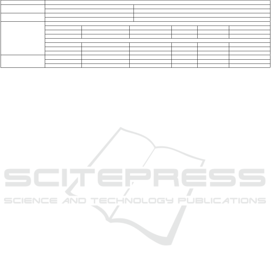
Table 1: Table on the quantified key performance indices for some of our modules we have researched by now.
Module KPIs
Model Predictive Control
Mean lateral error in curves Mean lateral error on straight section
0.9 [m] 0.1 [m]
System Delays
Mean steering delay Mean engine RPM delay
200 [ms] 100 [ms]
Mission Planning (SHOP3)
Idle-time [min] of fleet after 8 hours in simulation
Senario Name Number of vehicles simulated Strategy 1 Strategy 2 Strategy 3 Strategy 4
Simulation Scenario 1 75 25782 26096 26046 25938
Simulation Scenario 2 40 2093 5343 3512 3084
Overall hauled ressources [t]
Scenario Name Number of vehicles simulated Strategy 1 Strategy 2 Strategy 3 Strategy 4
Simulation Scenario 1 75 18550 18550 18550 18550
Simulation Scenario 2 40 13865 12685 13080 10305
Object Detection
Model mAP@0.5 Person mAP@0.5 Wheel-dumper mAP@0.5 Car mAP@0.5 Beacon Detection Frequency [hz]
PointPillar (3D)* 0.34 0.4 0.4 - 20
YOLOv5m (2D) 0.994 0.978 - 0.966 30
033R126CN.
REFERENCES
Aeberhard, M. (2015). Automated Driving with ROS at
BMW. In ROSCon Hamburg.
Batterham, R. (2017). The mine of the future – even more
sustainable. Minerals Engineering, 107:2–7. Sustain-
able Minerals.
Bhattacharya, P. and Gavrilova, M. L. (2007). Voronoi di-
agram in optimal path planning. In 4th International
Symposium on Voronoi Diagrams in Science and En-
gineering (ISVD 2007), pages 38–47.
Chajan, E., Schulte-Tigges, J., Reke, M., Ferrein, A., Math-
eis, D., and Walter, T. (2021). Gpu based model-
predictive path control for self-driving vehicles. In
2021 IEEE Intelligent Vehicles Symposium (IV), pages
1243–1248.
Clausen, E. and Sörensen, A. (2022). Required and desired:
breakthroughs for future-proofing mineral and metal
extraction. Mineral Economics, 35(3):521–537.
Delrobaei, M. and McIsaac, K. A. (2011). Design and steer-
ing control of a center-articulated mobile robot mod-
ule. Journal of Robotics, 2011.
Donner, R., Rabel, M., Scholl, I., Ferrein, A., Donner,
M., Geier, A., John, A., Köhler, C., and Varga, S.
(2019). Die Extraktion bergbaulich relevanter Merk-
male aus 3D-Punktwolken eines untertagetauglichen
mobilen Multisensorsystems.
Ferrein, A., Scholl, I., Neumann, T., Krückel, K., and Schif-
fer, S. (2019). A System for Continuous Underground
Site Mapping and Exploration. In Reyhanoglu, M.
and Cubber, G. D., editors, Unmanned Robotic Sys-
tems and Applications, chapter 4. IntechOpen, Rijeka.
Goldman, R. P. and Kuter, U. (2019). Hierarchical task net-
work planning in common lisp: the case of shop3. In
ELS, pages 73–80.
Lang, D., Friedmann, S., Häselich, M., and Paulus, D.
(2014). Definition of semantic maps for outdoor
robotic tasks. In 2014 IEEE International Conference
on Robotics and Biomimetics (ROBIO 2014), pages
2547–2552.
Limpert, N., Schiffer, S., and Ferrein, A. (2015). A local
planner for ackermann-driven vehicles in ros sbpl. In
2015 Pattern Recognition Association of South Africa
and Robotics and Mechatronics International Confer-
ence (PRASA-RobMech), pages 172–177. IEEE.
Macenski, S., Foote, T., Gerkey, B., Lalancette, C., and
Woodall, W. (2022). Robot operating system 2: De-
sign, architecture, and uses in the wild. Science
Robotics, 7(66):eabm6074.
Macenski, S., Martin, F., White, R., and Ginés Clavero, J.
(2020). The marathon 2: A navigation system. In
2020 IEEE/RSJ International Conference on Intelli-
gent Robots and Systems (IROS).
Maruyama, Y., Kato, S., and Azumi, T. (2016). Ex-
ploring the performance of ros2. In Proceedings of
the 13th International Conference on Embedded Soft-
ware, pages 1–10.
Moore, T. and Stouch, D. (2014). A generalized extended
kalman filter implementation for the robot operating
system. In Proceedings of the 13th International Con-
ference on Intelligent Autonomous Systems (IAS-13).
Springer.
Mühlens, L. (2021). A Behaviour Engine for an Au-
tonomous Mining Vehicle in ROS. Bachelor’s thesis,
FH Aachen University of Applied Sciences.
Musin, O. R. (1997). Properties of the delaunay triangula-
tion. In Proceedings of the thirteenth annual sympo-
sium on Computational geometry, pages 424–426.
Nikolovski, G., Reke, M., Elsen, I., and Schiffer, S. (2021).
Machine learning based 3D object detection for navi-
gation in unstructured environments. In IEEE Intelli-
gent Vehicles Symposium Workshops, IV 2021, pages
236–242. IEEE.
Petty, J. (2017). Getting the best out of autonomous mining
fleets. AusIMM Bulletin, (Dec 2017):58–62.
Pingel, T. J., Clarke, K. C., and McBride, W. A. (2013). An
improved simple morphological filter for the terrain
classification of airborne lidar data. ISPRS Journal of
Photogrammetry and Remote Sensing, 77:21–30.
Pivtoraiko, M., Knepper, R. A., and Kelly, A. (2007). Op-
timal, smooth, nonholonomic mobile robot motion
planning in state lattices. Robotics Institute, Carnegie
Mellon University, Pittsburgh, PA, Tech. Rep. CMU-
RI-TR-07-15.
Poggenhans, F., Pauls, J.-H., Janosovits, J., Orf, S., Nau-
mann, M., Kuhnt, F., and Mayr, M. (2018a). Lanelet2:
A high-definition map framework for the future of
Towards a Fleet of Autonomous Haul-Dump Vehicles in Hybrid Mines
287

automated driving. In 2018 21st International Con-
ference on Intelligent Transportation Systems (ITSC),
pages 1672–1679.
Poggenhans, F., Pauls, J.-H., Janosovits, J., Orf, S., Nau-
mann, M., Kuhnt, F., and Mayr, M. (2018b). Lanelet2:
A high-definition map framework for the future of
automated driving. In 2018 21st international con-
ference on intelligent transportation systems (ITSC),
pages 1672–1679. IEEE.
Qi, C. R., Su, H., Mo, K., and Guibas, L. J. (2017). Point-
Net: Deep Learning on Point Sets for 3D Classifica-
tion and Segmentation. In The IEEE Conference on
Computer Vision and Pattern Recognition (CVPR).
Reke, M., Peter, D., Schulte-Tigges, J., Schiffer, S., Fer-
rein, A., Walter, T., and Matheis, D. (2020). A Self-
Driving Car Architecture in ROS2. In 2020 Interna-
tional SAUPEC/RobMech/PRASA Conference, pages
1–6. IEEE.
Rosen, D. M., Mason, J., and Leonard, J. J. (2016). Towards
lifelong feature-based mapping in semi-static environ-
ments. In 2016 IEEE International Conference on
Robotics and Automation (ICRA), pages 1063–1070.
Sánchez, F. and Hartlieb, P. (2020). Innovation in the min-
ing industry: Technological trends and a case study of
the challenges of disruptive innovation. Mining, Met-
allurgy & Exploration, 37(5):1385–1399.
Sürken, D. (2021). Programmierung einer Basisautoma-
tisierung für eine Wacker Neuson 1501 Modellmulde.
Bachelor’s thesis, FH Aachen University of Applied
Sciences. in German.
Tipaldi, G. D., Meyer-Delius, D., and Burgard, W.
(2013). Lifelong localization in changing environ-
ments. The International Journal of Robotics Re-
search, 32(14):1662–1678.
ICAART 2023 - 15th International Conference on Agents and Artificial Intelligence
288
