
Bed Management System Development
Flannag
´
an Noonan
a
, Juncal Nogales, Ciar
´
an Doyle, Eilish Broderick and Joseph Walsh
b
IMaR, Munster Technological University, Kerry Campus, Clash, Tralee, Kerry, Ireland
{flannagan.noonan, juncal.nogales, ciaran.doyle, eilish.broderick, joseph.walsh}@mtu.ie
Keywords:
Bed Management, Hospital Administration, Patient Throughput.
Abstract:
The costs of supporting hospitals are rising, bed numbers are falling and a growing population living longer
will require more hospital visits over their lifetime. Thus there is a global focus on increasing the efficiency of
patient throughput in a hospital. Bed management systems are still commonly paper-based and are effectively
memory-less from the hospital point of view. The hospital information systems are typically billing and
ordering systems with minimal information on patient movement along the patient pathway. The literature
suggests that technology and shared information allow for shared views to model and predict usage to better
manage finite resources. Paper-based systems work against this. This paper presents the design considerations
for a bed management application developed in conjunction with a local private hospital. The application
developed, provides a hospital-wide view of patient and bed status by recording and capturing touchpoints,
that is patient-hospital interactions. Furthermore, it captures data electronically such that the data can be
used for analysing patient presentation and bed moving with a view to improve bed management and patient
throughput.
1 INTRODUCTION
The escalating costs, in the European Union (EU),
for hospital funding is discussed in Schwierz, 2016.
The paper also highlights that bed numbers are drop-
ping, due to cost pressures and the changing health-
care model. EHealth it suggests “may increase quality
of service and create savings in hospital care”.
Paper based systems, still common in hospitals,
are best effort systems and hence can increase stress
on people delivering them, due to extra effort re-
quired at times due to unplanned events. Paper
based systems create information silos that detracts
from a common understanding across the organisa-
tion. Multi-disciplinary teams needs a common view
of the information to make informed decisions and in-
formation silos detract from this.
Efficient management is key to delivering the
maximum services to patients as quickly as possible,
which is a good societal goal and delivers better value
for taxpayer or health insurance funding.
This paper discusses the development of a bed
management application in conjunction with a local
hospital, one hospital in a hospital group providing
private healthcare in Ireland. The proposed system
a
https://orcid.org/0000-0001-9624-5181
b
https://orcid.org/0000-0002-6756-3700
provides a number of touchpoints, patient-hospital in-
teractions, that can identify, in real time, where the
patient is in the patient pathway. The goal is to an-
swer the question ”can data around patient interac-
tion events (touchpoints) be gathered with a view to
allow meaningful comparison of individual patient
journeys?”.
2 BED MANAGEMENT ISSUES
Bed management is a key area in addressing patient
throughput in a hospital. Literature indicates issues
with current bed management practices and suggests
three areas of improvement: Communications; Pro-
cess change; Modelling and Prediction. In all of these
areas data is required for their implementation.
2.1 Admissions & Discharge
At a high level, the bed management process is, where
a patient, either elective or emergency, is admitted to
the hospital, placed in a bed and is treated. Following
treatment, the patient is discharged, the bed occupied
by the patient is renewed for the next patient and fol-
lowing renewal is made available to bed management
for placement of another patient.
376
Noonan, F., Nogales, J., Doyle, C., Broderick, E. and Walsh, J.
Bed Management System Development.
DOI: 10.5220/0011690300003414
In Proceedings of the 16th International Joint Conference on Biomedical Engineering Systems and Technologies (BIOSTEC 2023) - Volume 5: HEALTHINF, pages 376-383
ISBN: 978-989-758-631-6; ISSN: 2184-4305
Copyright
c
2023 by SCITEPRESS – Science and Technology Publications, Lda. Under CC license (CC BY-NC-ND 4.0)

Admission and discharge are the areas that bed
management can most influence and thus there is a
large focus on both areas. Destino et al., 2019; Cho
et al., 2017; Patel et al., 2017; Mustafa and Mahgoub,
2016, all cover initiatives to improve early discharge
by focusing on process change and record the effects
of these changes. However, James et al., 2019 and
Rachoin et al., 2020, both suggest that the impact on
Length of Stay (LOS) holds true for surgical patients
but not for medical patients.
Given that a multidisciplinary team is responsi-
ble for discharge, shared information is key to man-
aging and streamlining the process. This was high-
lighted in the studies above, where communication
was a key factor contributing to the initiatives. Paper-
based, mostly manual systems do not lend themselves
to easy communications of status and create an over-
head making the initiatives difficult to sustain.
2.2 Modelling
Bed management can be aided by modelling tech-
niques. Modelling is very dependent on historic data
to train and test the models and paper based systems
do not lend themselves to easy extraction of the data,
as input to models. Thus the capture of electronic data
allows for shared information for management on a
day by day basis. Additionally, these systems allow
gathering of data over a period of time, which can be
used to model and predict patient patterns to improve
patient throughput.
2.3 Partner Hospital
The main computer based record system in the part-
ner hospital is the Hospital Information System (HIS),
primarily an ordering and billing system. The HIS is
used to capture patient details when presenting for ad-
mission and updated sometime after patient discharge
to show the bed available again. Until this happens,
the bed is not available to other patients.
The current bed management system is paper-
based and manual and to a large extent memory-less,
in that each day a new paper model is populated
from the HIS and the previous day’s transactions for-
gotten. This does not lend itself to easy review of
previous transactions to determine how the current
method could be improved or made more efficient.
The memory-less system limits discussion as the in-
formation and lessons learned rests with individuals
and are not easily shared.
The HIS is not used by staff as a first point of call
to get visibility of patients in the hospital relying in-
stead on word of mouth or walking the wards. Re-
quests for beds to be renewed are made directly to the
Housekeeping staff on the ward. This contributes to
the creation of information silos and a lack of real-
time information. This lack of a shared view of the
hospital occupancy, limits the visibility to a per ward
basis, and inhibits administration of bed management
on a whole hospital basis, creating inefficiency.
3 DEVELOPMENT OF A SYSTEM
FOR BED MANAGEMENT
This section describes the development of the appli-
cation. Being based in the hospital allowed access
to clinical, administrative and housekeeping staff to
gain a fundamental understanding of the hospital op-
eration.
3.1 Requirements Gathering
An understanding of what was required was largely
developed from documenting the high-level processes
associated with the normal hospital operation, the pa-
tient pathways and supporting processes. Addition-
ally, commercially available systems were examined.
Most fell short of something that could be easily in-
tegrated into the hospital and the development of a
bespoke system was undertaken.
Requirements gathering was primarily influenced
by discussions with the Hospital Manager and the Bed
Manager. In addition to the Bed Manager, the role
was covered, outside of core hours, by the Assistant
Director of Nursing (ADON) and their input was cap-
tured also. The Clinical Nurse Manager (CNM) for
the Dayward covered bed allocations for that ward
and contributed to the requirements. Interviews with
staff, shadowing some roles and observing the hos-
pital functioning all contributed to understanding the
requirements for data capture. Review of the commer-
cially available systems created a focus on developing
a coherent system to manage the patient along the pa-
tient pathway while highlighting the bed renewal re-
quirement and recording its completion.
Of note is that the bed renewal process involves
both Housekeeping and Healthcare Assistant (HCA)
staff. Bed renewal is complete when both roles com-
plete their respective tasks.
A goal was to minimise any overhead a new sys-
tem would impose, while providing benefit in terms
of visibility. A series of screen mock-ups were cre-
ated as a basis for discussion and feature definition
with the Hospital Manager and Bed Manager. Sub-
sequently a series of Hypertext Markup Language
Bed Management System Development
377

(HTML) pages were produced to illustrate the User
Interface (UI) concepts.
3.2 Requirements Recorded
Based on the above work, the requirements were de-
fined at a high level as:
• Facility to allocate a bed to a patient
• Facility to move a patient between beds
• Facility to capture a patient details for later admis-
sion
• View wards and determine their occupancy
• View beds pending renewal
• Update beds to indicate renewal completed
• View bed availability
• View bed occupancy
• Filter bed criteria
The requirements definition included using bar-
codes as the means to identify staff, patients and beds.
This reasoning was twofold. Firstly, as part of the Ad-
missions process, the patient bracelet identifying pa-
tients contained a barcode representation of the data,
thus being readily available. Secondly, a concurrent
project was using barcode identifiers as the mecha-
nism for identifying staff, patients and beds; and thus
a commonality of techniques would serve for easier
deployment of the application and training of, and ac-
ceptance by, the users.
4 SOFTWARE DEVELOPMENT
The following sections discuss the development of the
various software elements that constitute the applica-
tion.
4.1 Model Choice
A web based or browser based application was con-
sidered as the most suitable model for the applica-
tion since it would be available across any device that
could support a browser, including personal comput-
ers, tablets and phones regardless of the operating sys-
tem installed on the device. Additionally, updates to
the software could be pushed out by simply updating
the software in a single location, rather than having to
update individual clients.
A web browser, from a perspective of the Bed
Manager and other administrative roles, functioned
well, due to their ready access to a computer or de-
vice. From a perspective of other data entry roles such
as HCA, Housekeeping and the Admissions staff, this
was perceived as restrictive. Housekeeping particu-
larly did not routinely access computers, thus it would
be great change in work practice to adopt this. Sim-
ilarly, for the HCA roles fulfilling the patient escort
function, the mobility elements would make using a
computer terminal counterproductive. Thus in addi-
tion to the web architecture a method to provide mo-
bility with ease of access was required. Given the
ubiquity of mobile devices and their general accep-
tance and use, a medical grade mobile phone as a
means of data input was considered as central to a ro-
bust roll out. The addition of a web service element,
to allow data entry from those functions that are mo-
bile or entering very defined data, was viewed as a
definite requirement.
A Model View Controller (MVC) pattern was cho-
sen for the web application, since this would allow
the main processing to be retained on the server, es-
sentially requiring very basic computing power on the
user device. This enhances the range of devices that
could use the application. The MVC pattern is more
supportive of changes to one of the layers whilst min-
imising impact on the other layers, than other pat-
terns. A separate controller was built to accommodate
additional mobile devices and operating the mobile
views via a web service, extending the architecture.
Fig. 1 represents the model as implemented.
Figure 1: Design Model for Bed Management Application.
4.2 Database Elements
The database, conceptually, began with a bed need-
ing to be associated to a patient for a period of time,
from the patient being allocated a bed through to them
using the bed and then being discharged.
An intermediary relationship is required to break
down the bed / patient many-to-many relationship and
a table called “StatusLog” was created to act as the
link. This uniquely capture all transactions between
all beds and all patients. Another requirement was to
identify when a bed needed cleaning, and this could
also be captured as a status.
HEALTHINF 2023 - 16th International Conference on Health Informatics
378

Six bed statuses were defined: Allocated Pending;
Allocated on site; Occupied; Out of Service Pending
(represented as “OOS Pending”); OOS In Progress;
Available. The status change transitions are recorded
in table 1. Each bed cycles through these statuses as
patients are treated. A “Status” table was created to
capture these and referenced by a foreign key. The
original bed status starts as “Indeterminate”, which
is where no “StatusLog” database entry exists for the
bed. A bed with status “Indeterminate” can be allo-
cated to a patient; the proviso being that the onus is on
the person allocating to ensure that the bed is available
to accept a patient. Once a bed has gone from the “In-
determinate” status, it will continually cycle through
the defined statuses in the normal course of events.
Another mechanism to remove the “Indetermi-
nate” status is via the bed renewal process. It was
envisioned that, when the application was first de-
ployed and all beds had “Indeterminate” associated
with them, a situation would arise where Housekeep-
ing and HCAs would be asked to renew a room with
this status. Thus by scanning the barcode of a bed
to indicate completion of bed renewal, the bed sta-
tus would be changed from “Indeterminate” to “Avail-
able”. Thereafter, it would cycle through statuses as
shown in Table 1.
A key field in the StatusLog table was the times-
tamp associated with a status record, called “Record-
Time”. This timestamp allows the current status
of a bed to be identified by searching on the lat-
est timestamp associated with a bed. The use of a
“where” clause allows searching within the “Status-
Log” records as in
WHERE RecordTime = (SELECT MAX(RecordTime) FROM StatusLog
WHERE Bed_Fk = Bed_Pk)
AND Bed_Fk = Bed_Pk
The second repetition of Bed Fk = Bed Pk is to dis-
tinguish between multiple beds with the same times-
tamp, a common SQL technique.
Once that arrangement had been made, the other
Table 1: Bed Status Transitions.
Status Steps Status Change Notes
Patient Allocated to
Bed
Available → Allocated
Pending
Bed Manager;
ADON; Dayward
CNM
Patient scanned at
Admissions
Allocated Pending →
Allocated On Site
Patient Details
Captured
Patient Admitted
via Bedside Scan
Allocated On Site →
Occupied
HCA Patient
Escort
Patient Treated Occupied No Data Collected
Patient Discharged
Occupied → OOS
Pending
Captured at Ward
or Reception
Bed Accepted for
Cleaning Or
Dressing
OOS Pending → OOS
In Progress
HCA &
Housekeeping
Accept via
Application
Bed Recorded
Cleaned &
Dressed
OOS In Progress →
Available
HCA &
Housekeeping
Confirm via Scan
tables followed supporting the basic tables of “Bed”
and “Patient”. A room is a collection of one or more
beds and a ward is a collection of rooms. The Room
table was used as a grouping to enable gender changes
on the bed collection associated with it. When a pa-
tient of a specific gender was admitted, or the last pa-
tient in a room was discharged, the gender of the room
would change.
4.3 User Interface
The User Interface (UI) is divided across the Web
Browser application and the Android application on
the medical grade mobile phones. The mobile phone
UIs are focused on data entry and are much more cur-
tailed in terms of visibility of the status on the wards.
On the Web Browser, the concept of letting the
user view each ward, as a floor plan, was formulated.
It was felt that the user would be best able to relate
to this view of the beds since they traversed the wards
continuously, day in day out. Each ward would be
represented by a single web page. Each bed would
be colour coded to a gender, either male, female or
non-gender. Single rooms and some wards are not
segregated on a gender basis, such as the High Depen-
dency Unit Ward and the Children’s Ward. For multi
bed rooms the bed gender is dictated by the gender of
the person being first assigned to that room due to the
hospital’s single sex room policy.
4.3.1 Web Application UI
Each bed is represented by a rectangle and is filled
with a colour denoting the associated gender; pink for
female, blue for male and orange for gender neutral
beds. To give a visual indication of whether a bed
was available or not the concept of a diagonal strike
through the bed was created. These two features com-
bined allow a quick visual indication of the bed situa-
tion in a ward.
The graphic image of the ward is a Scalable Vec-
tor Graphic file and the bed rectangles have the back-
ground colour changed when the gender changes. The
diagonal strike width setting is changed from 0 to a
value when a bed is occupied. When a patient has
been discharged on the system, the bed is automati-
cally put out of service (OOS) and the diagonal strike
and the border are changed to a yellow colour to pro-
vide visual indication that the bed is pending renewal.
In addition to the visual diagram, information re-
garding the bed population was also included in the
text and as a pie chart at the top of the page, as a
form of dashboard for the ward. A function was im-
plemented to provide patient details for occupied beds
Bed Management System Development
379

when the mouse hovered over the bed rectangle us-
ing a pop up canvas. This provided the patient name,
Medical Record Number (MRN) and whether they
were under isolation or not. This is illustrated in Fig.
2 by the large blue rectangle with the yellow band.
The yellow band with the red text gives a strong
visual indicator that the bed has a second association
with it. In the example given, the bed is OOS but the
bed has been allocated to a patient for when the bed
renewal is complete. There is also an indicator at the
top right-hand side of the ward view, of beds that have
been earmarked. Another potential scenario for using
the earmarking feature, is when a patient is known to
be imminently discharged then a second patient can
be earmarked for that bed. This scenario can only
be used for medical emergency patients, given their
stochastic nature. Elective patients should be well de-
fined and hence not added in this manner.
The ward layouts are fixed, taken from a floor plan
and changing them would be a task for the developer.
However, the number of beds in a hospital is a func-
tion of agreement with the hospital insurers and is not
a simple change to vary the number of beds. Addi-
tionally there is a large reliance on routine, due to
safety concerns. Thus there is a large inertia to over-
come in changing the structure of the hospital. Hence,
it is not something that would happen often and would
require some planning. Changes to the display could
be incorporated into that planning.
A visual reminder has been created of a patient
waiting on a bed. Previously, this would have been
done on a sheet of paper and this paper would have
been archived at the end of the day. Now, a record is
held, of each earmarked patient. These records can be
reviewed and analysed to identify patterns of capacity
constriction, potentially aiding efficient bed manage-
ment.
Figure 2: UI Ward View Test Application .
There is a screen for each of the seven wards, all
similar to that represented in Figure 2 and accessible
via the buttons above the dashboard. There are also
other screens available both to the Bed Manager and
other hospital roles. For the Bed Manager role, their
buttons are similarly available at the top right of the
ward screen.
The “Assign Patient” screen presents a collection
of buttons, one per ward, that click through to the
ward screens, where the underlying functionality is
designed to allow a bed to be clicked and a patient as-
signed to that bed. Similarly, there is a screen that al-
lows the Bed Manager to release a bed from a patient
that is known to have been discharged. The scenario
of usage might be that the Bed Manager is informed
by Nursing that a patient has been discharged; and
thus the Bed Manager can release the bed, to create
an entry on the Housekeeping and HCA list of beds
to be renewed.
The Bed Manager has access, via another screen,
to the list of the beds currently out of service, detail-
ing the bed status in relation to completion. Another
screen allows the Bed Manger to capture details of
patients being referred for admission by GPs. The pa-
tients are added to a “Pending Admissions” list. Each
list item has an “admit” button that allows the Bed
Manager to select a ward for a view of that ward,
where the patient can be admitted. Generally, when
taking calls from GPs with regard to accepting a pa-
tient from Admissions, it can not be done immedi-
ately as there are other factors to consider. This allows
a patient’s details to be recorded, and then the Bed
Manger can come back to the list and admit patients
when circumstances are aligned to allow admission.
Figure 3 shows a screen providing an overview
of the bed status for the hospital as a whole. This
screen is also available to the Hospital Manager’s lo-
gin and could be extended to other roles as required.
This view provides a breakdown of the bed availabil-
ity and status by ward. The default view shows the
Available Beds in the blue buttons and below them a
view grouped by bed type of bed statuses.
The filtering capability for Bed Category provides
for availability of single beds or shared beds. Once a
filter is selected, the per ward view updates to display
the details, updating the text to reflect the filter. The
grouping statuses update to reflect the filtered view
also. Similarly for the Status By Ward filter, the text
and figures, on the buttons, changes to reflect the view
of cleaning by ward. The per ward view for cleaning
status is deemed useful since it shows potential beds
to be made available imminently. A separate page
is available to the Bed Manager that focuses only on
availability, essentially a subset of the overview view.
HEALTHINF 2023 - 16th International Conference on Health Informatics
380
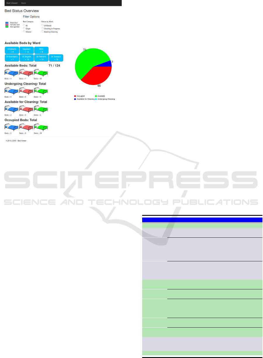
Figure 3: Hospital Bed Status Screen.
This page also provides pie charts giving a breakdown
of available beds by gender, per adult ward.
The main focus, on functionality, was for the
Bed Manager, with additional views for Housekeep-
ing and HCA to trigger the start of a room being
cleaned; deemed a supervisory function as the HCAs
and Housekeepers would have limited access to com-
puters. Additionally, a separate login exists for the
Hospital Manager that provides, amongst other fea-
tures, a screen to register users of the system.
4.3.2 Android Application UI
The purpose of the Android UI is to allow an easy
mechanism to capture data. The devices used the in-
herent scanning functionality of this class of device
to capture details via barcodes, both for patients and
bed locations. This circumvented the need to manu-
ally enter information and thus reduce the possibility
of error. The development focus was to reduce the
number of button clicks required to capture the data.
The initial screen for the Android Application is
a login screen. Login is achieved by scanning a bar-
code associated with a defined user on the database.
If the user exists, then the server will return a JSON
Web Token (JWT) to the device to allow it to con-
tinue communicating with the server. Without a cur-
rent JWT, the server will return “Permission Denied”.
The JWT is set to expire after one hour but that is
purely a nominal time, in the absence of any usage in-
formation. In addition to a hashed private secret key
element for security, the JWT contains the user name
and role used in the initial exchange and that dictates
the screens available to the user. Table 2 lists the roles
and the associated functionality.
A controller in a separate project is used as the
Web Service for the mobile application, although it
still uses the database access layer model in the main
application to access data. The interaction between
the mobile devices and the application is very defined
with small data sets being passed up to the server.
Confirmation messages or confirmation data is passed
back to the mobile device. Given the use of barcode
scanning to capture data and list selection as the only
other data entry mechanism, the solution is robust to
data entry errors.
One issue arose where, when a medical patient’s
details were entered, based on a GP referral, typo-
graphical errors crept into the data entry. Thus, when
the actual patient details were scanned to admit the
patient, the patient could not be admitted because
their details did not match the details entered on the
application.
This led to the development of an additional
screen for Admissions to allow them to select a name
from the list of patients pending admission and the
patient database entry was subsequently updated such
that where both existing and scanned patients have the
same MRN, or the existing patient has no MRN and
the scanned patient does not exist in the application
database the scanned patient details and the MRN if
Table 2: Android Device Screens.
Role Usage Screens
All Users Login Main Screen
Scan the patient Admissions
Set the Consultant Screen 1
Sets Finance Office Visit
Required
Admission Sets Escort Requirement
Admission Screen
2
Sets Straight to Ward or Tests
Chooses the correct patient
details if difference between
scanned and application
details
Admissions Screen
3
Choose an Action, opens
another screen
Patient Escort
Screen 1
Scan a Patient
Patient Escort
Screen 2
HCA
Patient
Scan a Bed
Patient Escort
Screen 3
Escort
Select A Direct to Ward
Patient
Patient Escort
Screen 4
Select a Patient for Test
Patient Escort
Screen 5
Record Transfer Complete
Patient Escort
Screen 6
HCA &
House-
keeping
Record a Bed Renewal
Complete
Bed Renewal
Screen
Reception Record a Patient Exit Release Screen
Bed Management System Development
381

applicable are applied to the database.
Alternatively, where the scanned patient MRN ex-
ists in the application database but is different to the
MRN of the patient allocated, or the allocated patient
has no associated MRN; then the “StatusLog” pa-
tient primary key reference will be changed to that of
the scanned patient. Otherwise a new patient record,
where the existing patient allocated to a bed, does not
have an MRN and the scanned patient MRN does not
exist in the database.
5 DEPLOYMENT & TESTING
The system was deployed in the hospital with the ap-
plication running on a laptop acting as a server. The
laptop was supplied with an IP address on an internal
Virtual Local Area Network (VLAN) and mobile de-
vices with IP addresses on this VLAN could commu-
nicate with the application and through to the applica-
tion database. Fig. 4 was the planned deployment but
due to the time to get the server deployed in the data
centre, the testing was carried out using the laptop as
the server. Thus the “Hospital Data Centre” role was
implemented using the laptop, the laptop also func-
tioned as a workstation for using the Web UI and the
hospital VLAN provided the network transport from
the mobile devices to the IIS and SQL servers.
The purpose of the testing was to provide the Hos-
pital Manager with an understanding of the full capa-
bility of the system and to demonstrate the system and
the functionality to other staff members, particularly
the Bed Manager and the ADONs.
To test the application, the daily patient arrival,
discharge and transfer data were entered onto the ap-
plication, following the additional steps that would
not normally be captured in the hospital, see Table 3
below. Although the timing data was not valid, due to
the data being retrospectively added, it did allow the
data to be captured, proving that this data could be
collected. Over the course of the testing, from Octo-
ber 2019 through the beginning of March 2020, small
coding anomalies arose and were addressed.
6 RESULTS
Four-hundred and sixty eight patients were processed
on the application between October 2019 and March
2020. Testing was interrupted due to a staff mem-
ber departing followed by a recruitment cycle. Based
on hospital provided figures from 2016, some 50 dis-
charges a day would be expected to occur. Thus the
actual test quantity achieved is low but is sufficient
to give an understanding of how the application per-
forms.
The Hospital Manager, who carried out several
days testing, did perform data entry over the entire
patient pathway data recording and also the bed re-
newal recording. The Hospital Manager, required a
short training session to grasp the functionality. Some
features required elaboration which validates the need
for training and discussion when introducing a new
system. When considering that the application, de-
signed for use by multiple roles, was being used end
to end by people using the full functionality with less
than an hour’s training, this is illustrative that the ease
of use criterion has been met.
Table 3 compares the features or data capture
points, that currently exist between the Hospital In-
formation System and paper based records kept lo-
cally and the application as implemented. This shows
that significantly more detail is captured with the pro-
posed system and can identify where a patient is along
the patient pathways.
The feedback on the application, both the web
browser and mobile device sections, from the Hospi-
tal Manager, supported the ease of use on the device.
She felt the ease of use would lower the barrier to
adoption. The use of the Receptionist role, to the re-
lease the bed and create an event highlighting the need
for the bed to be renewed, was viewed as a critical fea-
ture. This allowed the highlighting of this task auto-
matically, decoupling it from the Nursing role, where
it could sometimes get overlooked due to Ward pres-
sures. She thought that this feature, together with the
bed automatically being made available following re-
newal, led to a big improvement in the efficiency of
the hospital and bed allocation, for Medical Patients
presenting stochastically.
The Bed Manager felt that the paper based mech-
anism she used adequately allowed her to manage the
beds. She felt that the data entry required was onerous
Table 3: Event Capture Comparison.
Existing System New System
Desired Feature HIS
Local /
Individual
Global View
Pre-Allocate Bed to
Patient
No
Yes - Bed
Manager
Yes
Record Admission Yes No Yes
Record Arrival at bed No No Yes
Capture Patient
Egress From Hospital
No No Yes
Capture Bed Renewal
Requirement
No Yes - Nurse Yes
Bed Available
Notification After
Renewal
No
Yes -
Nursing /
H’keeping
Yes
Graphical View of
Patient Fill
No No Yes
HEALTHINF 2023 - 16th International Conference on Health Informatics
382
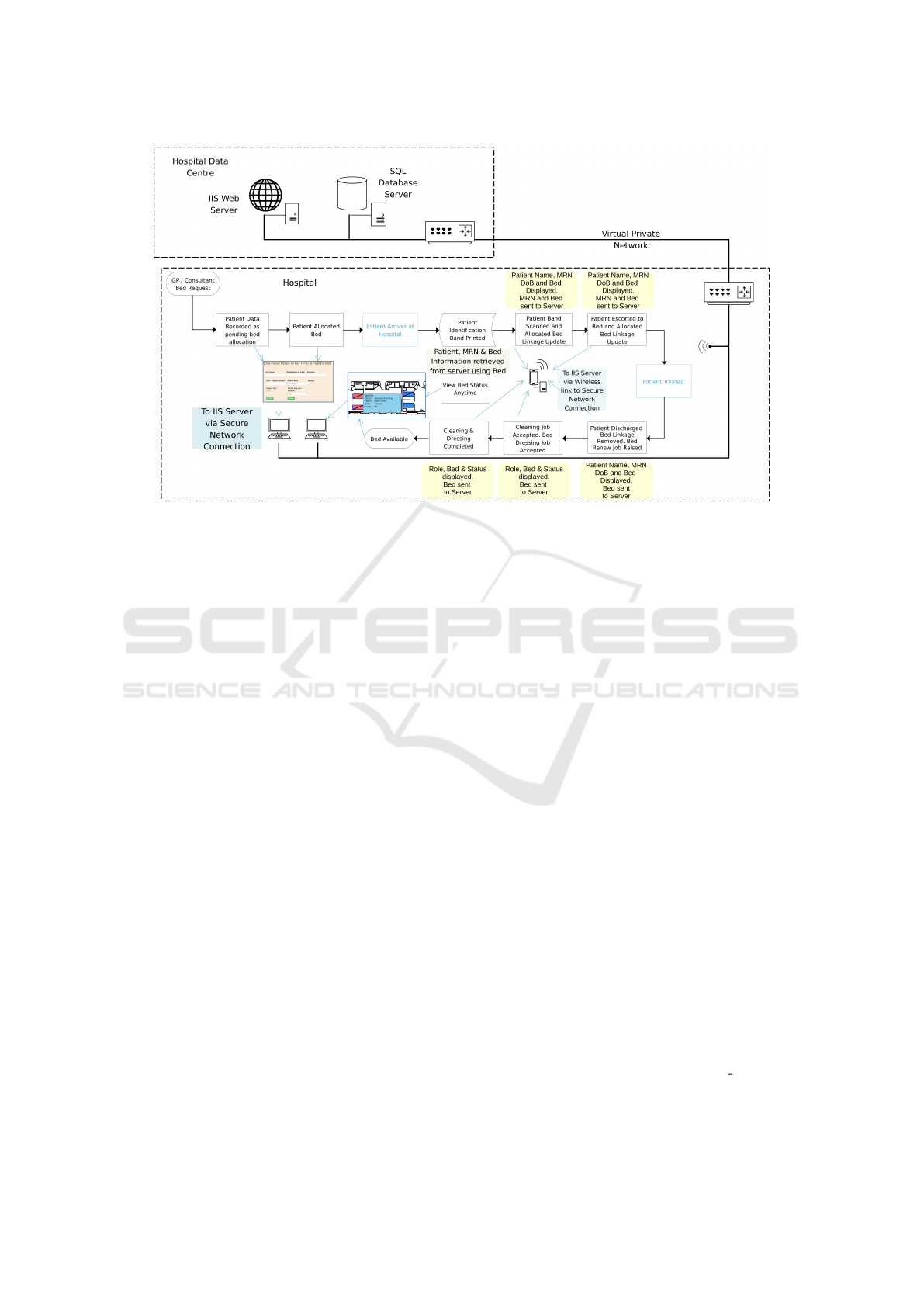
Figure 4: Planned Deployment and Data Capture Snapshot.
and was less efficient that her current system.
Some issues arose from this trial but were ad-
dressed. Some minor bugs were resolved in the soft-
ware. The use of a defined naming with a fixed date
of birth cause for patients caused an issue but was
resolved simply by appending the day of test to the
name.
Because data entry regarding patients was carried
out retrospectively, no picture can be formed of pa-
tient movement, timing from admission to reaching
the allocated bed and actual discharge times, but the
fact that these have been recorded as events, even with
artificial times, bodes well for data capture for use in
a live environment, which is a further stage.
7 CONCLUSIONS
The literature reviewed suggests data sharing as a
method for improvement of processes. This applica-
tion allows data to be captured and presented graphi-
cally and textually to provide a common view of hos-
pital status.
The system, as it exists, is a first step in being
able to pull together different elements of the patient’s
journey along the care pathway. The next stage is to
incorporate it into the overall information technology
of a hospital to allow live data capture.
REFERENCES
Cho, H., Desai, N., Florendo, A., Marshall, C., Michalski,
J., and amd A. Dunn, N. L. (2017). E-DIP: Early dis-
charge Project: A model for throughput and early dis-
charge for 1-day admissions. https://bmjopenquality.
bmj.com/content/5/1/u210035.w4128. Accessed 07
October 2022.
Destino, L., Bennett, D., Wood, M., Acuna, C., Goodman,
S., Asch, S. M., and Platchek, T. (2019). Improving
patient flow: Analysis of an initiative to improve early
discharge. Journal of Hospital Medicine, 14(1):22 –
27.
James, H., Steiner, M., Holmes, G., and J.R, S. (2019).
The association of discharge before noon and length
of stay in hospitalized pediatric patients. Journal of
Hospital Medicine, 14(1):28 – 32.
Mustafa, A. and Mahgoub, S. (2016). Understanding and
overcoming barriers to timely discharge from the pe-
diatric units. https://bmjopenquality.bmj.com/content/
5/1/u209098.w3772. Accessed 10 October 2022.
Patel, H., Morduchowicz, S., and Mourad, M. (2017). Us-
ing a systematic framework of interventions to im-
prove early discharges. The Joint Commission Journal
on Quality and Patient Safety, 43(4):189–196.
Rachoin, J., Aplin, K., Kupersmith, E., Gandhi, S., Travis,
K., Stefaniak, M., and Cerceo, E. (2020). Discharge
before noon: is the sun half up or half down? Ameri-
can Journal of Managed Care, 26(8):246–251.
Schwierz, C. (2016). Cost-containment policies in hos-
pital expenditure in the european union. https://
ec.europa.eu/info/sites/info/files/dp037 en.pdf. Ac-
cessed 11 October 2022.
Bed Management System Development
383
