
Evolving Behavioural Level Sequence Detectors in SystemVerilog Using
Grammatical Evolution
Bilal Majeed
1 a
, Conor Ryan
1 b
, Jack McEllin
1 c
, Ayman Youssef
2 d
, Douglas Mota Dias
1,4 e
,
Aidan Murphy
3 f
and Samuel Carvalho
5 g
1
BDS Labs, Dept. of CSIS, University of Limerick, Limerick, Ireland
2
Dept. of Computer and Systems, Electronics Research Institute, Cairo, Egypt
3
Dept. of Computer Science, University College Dublin, Dublin, Ireland
4
Dept. of Electronics and Telecommunications, Rio de Janeiro State University, Rio de Janeiro, Brazil
5
Dept. of Electrical and Electronic Engineering, Technological University of the Shannon,
Midlands Midwest, Limerick, Ireland
Keywords:
Evolvable Hardware, Sequence Detectors, Grammatical Evolution, Sequential Logic Circuits, Hardware
Description Language Design, Electronic Design Automation.
Abstract:
Sequential circuits are time-dependent circuits whose output depends not only on their current inputs but
also on previous ones. This makes them substantially more complex than combinational circuits, which are
stateless and only produce outputs from their current inputs. This paper demonstrates the automatic evolution
of some of the most critical and hard-to-evolve electronic sequential circuits, namely, sequence detectors. The
circuits are generated at behavioural level using the Hardware Description Language, SystemVerilog. We
successfully evolve solutions ranging in complexity from 3 to 5 bits, with and without encapsulation, and 6
bits with encapsulation while using Grammatical Evolution. A uniform distribution of values that a vector
of 50 bits can represent was used to generate the random training and test data sets to prevent any bias in
the solutions and results. While previous work combined shorter sequence detectors to produce longer ones,
for example, combining two 3-bit detectors to form a 6-bit detector, we produce all sequence detectors from
scratch without any intermediate stages. The system simply takes instructions and testcases and produces the
desired detector; we show that not only does it produce longer-sequence detectors than previous work, but it
also does it using fewer computational resources.
1 INTRODUCTION
Designing a digital circuit is a labour-intensive and
complicated process. It can be difficult, if not im-
possible, to fix bugs in electronic chips after they are
manufactured, costing millions of dollars. Therefore,
intelligent and time-efficient systems to design and
produce circuits are crucial. Circuit designers use
Hardware Description Language (HDL) when pro-
a
https://orcid.org/0000-0001-7528-275X
b
https://orcid.org/0000-0002-7002-5815
c
https://orcid.org/0000-0002-0187-9614
d
https://orcid.org/0000-0001-6145-4071
e
https://orcid.org/0000-0002-1783-6352
f
https://orcid.org/0000-0002-6209-4642
g
https://orcid.org/0000-0003-3088-4823
ducing complex circuits; Two languages are used pri-
marily to design the HDL systems: VHDL (Nav-
abi, 2007) and Verilog (Ciletti, 2010). SystemVer-
ilog (SV) (Spear, 2008) is a superset of Verilog,
which, in addition to being an HDL, is also a Hard-
ware Verification Language (HVL). This language
has several additional features, such as more data
types and support for object-oriented paradigms. In
this work, SV was used to design and evolve the cir-
cuits with and without encapsulation of grammar. Al-
though Field-Programmable Gate Arrays (FPGA) can
be used to test the circuits before they go through the
Application-Specific Integrated Circuit (ASIC) de-
signing and manufacturing process, efficient designs
of digital circuits require extensive human and com-
putational resources. Electronic Design Automation
(EDA) tools are used to design electronic circuits;
Majeed, B., Ryan, C., McEllin, J., Youssef, A., Dias, D., Murphy, A. and Carvalho, S.
Evolving Behavioural Level Sequence Detectors in SystemVerilog Using Grammatical Evolution.
DOI: 10.5220/0011689100003393
In Proceedings of the 15th International Conference on Agents and Artificial Intelligence (ICAART 2023) - Volume 3, pages 475-483
ISBN: 978-989-758-623-1; ISSN: 2184-433X
Copyright
c
2023 by SCITEPRESS – Science and Technology Publications, Lda. Under CC license (CC BY-NC-ND 4.0)
475

however, some of them automatically generate parts
for designers nowadays. Some machine learning-
based (Solido, 2005), and synthetic intelligence (SI)
based (Eagle, 1988; Kicad, 1992) automation tools
for the automatic design of digital circuits have been
proposed. The designers have to compromise on
something while designing a circuit manually or au-
tomatically. In our case, that compromise is on the
number of individuals used to evolve the larger and
more complex circuits. However, still, our system
uses fewer resources compared to the literature, as
shown in Table 4.
Evolutionary techniques have shown promising
results in evolving solution circuits for a given prob-
lem. Evolutionary Hardware (EH) uses algorithms
such as Genetic Algorithms, Genetic Programming
(GP) and Grammatical Evolution (GE) to evolve cir-
cuits. EH is divided into two categories, intrinsic
evolution (Zhang et al., 2004) and extrinsic evolution
(Kalganova, 2000). The circuit is created and evalu-
ated in intrinsic evolution by running the evolutionary
process on real hardware, such as FPGA. In extrinsic
evolution, the evolution is performed in software, us-
ing a simulator to verify the circuit by checking if it
passes all required tests.
Digital circuits are divided into two categories,
combinational and sequential. Combinational circuits
provide output as soon as input changes since their
output solely depend upon input. Sequential circuits,
in contrast, have a memory element attached to them
which holds information on the states of the circuit.
The output of sequential circuits depends on the sys-
tem’s present state and/or current input. Since each
state is dependent on the previous state, sequential cir-
cuits are used to run the systems which need to follow
a particular pattern. The required output of the sys-
tem is only generated if the expected pattern is cor-
rectly followed. A simple example of a sequential
circuit is a 3-bit counter, which must progress from
state ‘101’ to reach ‘110’, and cannot bypass the state
of ‘101’. Thus, it follows a defined pattern. Sequen-
tial circuits are the key elements of most electronic
gadgets nowadays since most devices multitask and
are usually driven by oscillator-based clocks.
A sequential circuit is usually represented as a Fi-
nite State Machine (FSM), a pictorial representation
of sequential circuits as shown in Fig 1. FSM com-
prises a certain number of states where the next state
depends on the current state and/or the current in-
put. There are two major types of FSMs, Moore and
Mealy. The mealy machine changes its output and
moves to the next state based on its current state and
the input, while the Moore machine’s output only de-
pends upon the current state. Therefore, the Moore
machine usually has more states than a Mealy ma-
chine and uses more hardware resources. The FSM
shown here in Fig 1 is a Mealy machine, and it can be
seen that the arrows that show the state transition are
labelled with input (on the left side of ‘/’) and output
(on the right side of ‘/’) of the system. The system’s
output is highlighted with green colour only when it
turns ‘1’.
S0
S1
0/0
0/0
1/0
1/0
S2
1/1
0/0
Figure 1: FSM of 3-bit ‘101’ SD.
A Sequence Detector (SD) is a particular sequen-
tial circuit that generates the required output only
when a desired correct sequence is detected. For
example, encryption in telecommunication is done
through different codes. If ‘1100’ means a red alert,
then a correct and on-time detection of this sequence
is critical, which means that this SD needs to be
highly responsive and always active. SDs have ex-
tremely diversified applications nowadays. From
static machines in medical clinics to flying aeroplanes
in the sky, SDs drive the systems perfectly and gener-
ate safe or unsafe system alerts in time.
In this paper, four different kinds of such SDs
have been generated automatically through the GE,
where the inputs and outputs of the SD are given to
the search engine to produce the circuit automatically.
All the SDs have different complexity levels, and we
successfully generated a correct circuit for each rele-
vant gold circuit. Notice that we refer to a gold circuit
here as a standard human-made circuit. A comparison
of the FSM of gold and evolved circuit can be seen in
Fig 6. The goal is to find a solution that can success-
fully mimic the function of the gold circuit, but being
exactly like the gold circuit is not a requirement here.
In fact, it is least desired since we want our system to
search and create diverse solutions.
The paper is organised as follows: Section 2 con-
tains a literature survey of previous work on evolving
sequential circuits, and Section 3 gives some back-
ICAART 2023 - 15th International Conference on Agents and Artificial Intelligence
476

ground about GE. Section 4 explains the method be-
hind generating the data set used for experiments.
Section 5 speaks about the structure of the test bench
used to simulate the circuits during the process of evo-
lution. Finally, the experimental setup, experiments,
and results are given in Section 6, followed by Section
7, having a conclusion and future work.
2 RELATED WORK ON
SEQUENTIAL CIRCUITS
The first EH research was presented (Higuchi et al.,
1993) in 1993 and claimed to be the first step towards
generating a Darwin machine (Calvin, 1987). In this
work, combinational circuits were evolved, such as
a 4-1 multiplexer using GA; however, sequential cir-
cuits were not explicitly touched. Following that,
the first-ever evolved sequential circuit was a sequen-
tial adder (Hemmi et al., 1996), which used the Pro-
duction Genetic Algorithm (PGA) (Mizoguchi et al.,
1994). PGA is a unique GA designed specifically for
EH, which uses a set of production rules in Backus
Naur Form (BNF), which they call HDL grammar.
Although they use a BNF grammar like GE (see Sec-
tion 3), their mapping process is entirely different
and inefficient as trees made by this grammar contain
much replication of terminals and non-terminals.
Two more sequential circuits, the modulo-6
counter and ISCAS’89 benchmark circuit, were
evolved (Shanthi et al., 2005) using Developmental
Cartesian Genetic Programming (DCGP). DCGP is
a modified form of CGP (Miller, 2011), which uses
two levels of evolution. In the first level of evolution,
the solution is found with the best input/output com-
binations and minimal hazards. In the second level
of evolution, the solutions are made entirely hazard-
free. It is computationally expensive compared to the
system presented here. In the following work, a 7-bit
sequence signal generator was evolved (Zhiwu et al.,
2011) through a fully connected feed-forward neural
network, which uses module circuits such as NAND
and XOR gates as basic network elements. It used a
GA for the evolution of this network to generate the
required SD.
The first evolved SD was presented (Ali et al.,
2004) in 2004. A 4-bit SD and a 6-bit SD were
evolved using a GA. The presented 6-bit SD is dif-
ferent from a traditional one. Firstly, it is a combi-
nation of two 3-bit sequences, ‘011’, where a single
FSM is used twice, which is not overly challenging
to evolve. Secondly, it keeps giving the ‘1’ as output
while it keeps detecting ‘011’, so if the input sequence
is ‘011011’, the output will be ‘111111’. Such a sys-
tem is specialised and not a generic automated tool
for evolving SDs. This system involves four differ-
ent stages to achieve the target. The system presented
in our work does the same job in just one stage: it
evolves the circuit, evaluates it using the fitness func-
tion in a single go, and is fully automated end-to-end.
Following them, the same hardware was evolved
(Popa et al., 2005) using GA and achieved a much bet-
ter and optimised circuit. Furthermore, they quoted
that their advanced solution consumes fewer hard-
ware resources than (Ali et al., 2004).
3-bit ‘110’ SD was extrinsically evolved (Yao
et al., 2007) using an incremental, evolutionary ap-
proach based on a GA, where small parts of a signifi-
cant circuit are evolved in the form of hardware mod-
ules in a small search space; which are then evolved
to generate the larger module-circuits and then these
larger module-circuits are used to evolve an entire cir-
cuit. However, due to the small search space, this ap-
proach is too restricted and unsuitable for evolving
large and complex circuits.
A 3-bit overlapping SD was evolved intrinsically
(Xiong and Rafla, 2009), which could detect sepa-
rate and overlapping sequences of ‘101’ and ‘100’.
However, the used approach with a small number of
states cannot be trusted for the intrinsic evolution of
large, complex, and immediately responsive systems
and are extremely hard to evolve and prohibitively ex-
pensive.
Similarly, (Tao et al., 2012) presented a system
that uses a GA to evolve the essential modules to be
used as the base of complete circuits, such as 4-bit
SD. However, the proposed method has three evo-
lutionary cycles, which is computationally expensive
for a small SD like a 4-bit SD.
In this presented work, we are evolving on the
behavioural level, which is recommended for com-
plex circuit designs (Mealy and Tappero, 2018). Be-
havioural level code is easier to interpret (CHU, 2008)
and more challenging to evolve (Ryan et al., 2020)
since it uses highly eloquent statements and functions
such as if-else conditions and for loops, respectively.
Much work has been done to evolve analogue
(Lohn and Colombano, 1998), (Zebulum et al., 1998),
(Stoica et al., 2000), (Barros et al., 2010) and digital
combinational circuits (Higuchi et al., 1993), (Miller
et al., 2000), (Tetteh et al., 2021), (Youssef et al.,
2021). However, only a few works addressed the
problem of evolving sequential digital circuits to find
a solution to a given problem (Ali et al., 2004), (Tao
et al., 2012) or optimise it (Popa et al., 2005). This is
at least partly because sequential circuits are difficult
to evolve due to the feedback loops required in the op-
eration of the circuits. The primary example of such
Evolving Behavioural Level Sequence Detectors in SystemVerilog Using Grammatical Evolution
477

loops is the structure of a flip flop, where the output of
one gate depends on the output of the second gate. If
anything goes wrong and the circuit glitches or faces
unexpected transition delays, the entire circuit is com-
promised and can generate the incorrect output. An-
other bottleneck in evolving sequential circuits is the
enormous amount of computational power required to
test the circuits for data sets (usually large and dif-
ficult to create) to get the best-fitted, reliable circuit
under all circumstances (Yao and Higuchi, 1999).
3 GRAMMATICAL EVOLUTION
GE (Ryan et al., 1998) is an evolutionary computation
technique that uses grammar to generate programs in
any arbitrary language. GE has shown promising re-
sults in circuit designing (Tetteh et al., 2021; Youssef
et al., 2021), symbolic regression (Ali et al., 2021),
and classification (Murphy et al., 2021). Moreover,
unlike a basic GA that generates bit string-based phe-
notypes, GE produces arbitrarily complex structures.
GE uses explicitly written grammar in BNF to map
genotypes to phenotypes. BNF is a meta-language
to write context-free syntactically correct grammar in
any desired programming language. BNF grammars
include four sections, usually: Terminals (T), which
can appear in the grammar and cannot be expanded,
such as ‘!’ and ‘ & ’ in our case; Non-Terminals (N),
which can be expanded further into T or other N, such
as < var > in our case; a set of Production Rules (P)
which is used to map N onto T, and Starting Symbol
(S), which is the part of N, and is associated to first P
in the grammar, as shown in Fig 2. The genotype con-
sists of a binary string and is mapped to a phenotype,
typically a program, by grammar. This genotype to
phenotype mapping can be seen in Fig 2. The binary
string can be divided into any desired number of bits,
but this chunk is usually 8 bits. Those chunks of 8
bits are then converted into integers, which are used
to generate a phenotype that includes only terminals.
In the shown example, the first integer in the geno-
type is 40. The mapping starts with the start symbol,
S. Since there are two options on the right side of the
first P, the modulus of 40 with two is computed. It re-
sults in 0, so the first option in this P is selected. Now,
since this option chosen is comprised of a set of N, the
leftmost is expanded. The second integer in the geno-
type is 118, and the number of associated options with
this leftmost N, i.e. (<var>), is two. So, the modulus
of 118 with two is computed, which turns out to be
0, and the first option, variable ‘x’, is selected. In the
next N, the modulus of 124 is calculated with the pos-
sibilities in that N, i.e. (<op>), which are three. The
Figure 2: Genotype to phenotype mapping in GE.
result turns out to be 1, so the second T, an OR gate,
is selected to replace this N. For the last N, the integer
is 137, and since there are two options in this N, i.e.
(<var>), the modulus of 137 with two turns out to be
1, so the second option is selected, which is ‘y’. The
final expression extracted can be seen in Fig 2, which
is an OR gate between two inputs, ‘x’ and ‘y’.
4 DATA SET GENERATION
The Mealy machine is used here to design the system
since it is known for its faster output change according
to the input, which means that, in our case, it indicates
the sequence detection as soon as possible. Therefore,
there needs to be a specific range of lengths for each
training vector (including input and respected output
sequence) to appropriately train the model in a diverse
and long enough sequence. However, this length is
optional for the test vectors but only if we want to
compute the test accuracy somewhat with training ac-
curacy. Using the scheme proposed in (Manovit et al.,
1998) if the Mealy machine is used, then according
to the number of states used and the number of in-
put bits, the following scheme given in Table 1 is fol-
lowed for the minimum and maximum lengths of bit
sequences used to train and test the model.
Table 1: Length of the sequences (in bits).
SD No. of States Min. Len. Max. Len.
3-bit 3 17 163
4-bit 4 25 163
5-bit 5 34 163
6-bit 6 45 163
The minimum length for all SDs is different from
each other, but the minimum length of 6-bit SD re-
sulted in 45; therefore, just to be on the safe side at
the boundary, each sequence was selected to be at
least 50-bit long. A batch of 1,000 balanced and ran-
ICAART 2023 - 15th International Conference on Agents and Artificial Intelligence
478

dom 50-bit sequences is designed where half of them
(500 sequences) have the respective sequence while
the rest do not.
5 TEST BENCH GENERATION
In HDL, the test bench is a piece of code and test
data to check whether the circuit is working correctly.
Usually, it could be more rigorous, but it becomes if a
large dataset is involved, especially while reading the
data from a file and writing the outputs into a sepa-
rate file. Our test bench is even more rigorous than
this because we had to design it from the perspective
of training a model, which means that all the func-
tions used should have been perfectly synchronised
and with the perfect timing delay used.
The generated test bench has four major parts, as
shown in Fig 3.
always @ negedge of clk
begin
#0.5
if (count == 0) begin
[inp_S,out_S] = testvectors;
b = inp_S[0:3];
end
else if (count < 50) begin
b = b<<1;
b = b + inp_b;
end
else begin
count = 0;
rst = 1;
out = 0;
end
end
always @ negedge of clk
begin
if (rst == 1) begin
rst = 0;
end
else if (rst == 0) begin
testcase();
end
end
Figure 3: Testbench algorithm to load the train/test data and
compute the fitness score.
The first part loads one complete sequence at a
time from the file that holds all 1,000 training se-
quences. One whole sequence is loaded into two dif-
ferent input (inp_S) and output (out_S) arrays. In
the second part of the test bench, batches are made
and loaded to evaluate the generated circuits. If it is
just the start of a sequence, the batch (b) of the first
four bits and the corresponding output will be loaded
to the variables used to evaluate the circuit for those
bits. Otherwise, in each cycle of the clock, that batch
of four bits will be given a left shift (b<<1), and then
the new bit (inp_b) will be inserted into it from the
right, and the process goes on till the sequence lasts.
The third part takes the most significant bit out of the
register and feeds it to the SV module, one bit per
clock cycle. The fourth part of the test bench eval-
uates using (testcase()) if giving this batch of in-
put bits to the system generates the same output as
expected. If it does, the fitness of that individual is
increased. This process is repeated for all the indi-
viduals, and each individual has to go through all the
1,000 sequences from this data file. The data set dis-
cussed above has 50,000 input and output bits, so the
best individual should have a score of 50,000, which
means that it has passed all the randomly generated
sequences and is ready to serve any new sequences
now.
6 EXPERIMENTS AND RESULTS
6.1 Experimental Setup, Tools and
Evolutionary Parameters
As noted in Section 3, grammars consist of four tuples
< S, P, N, T >. The grammar shown in Fig 4 is used to
evolve the 3-bit ‘101’ SD. The exact format is used in
the grammar for the other SDs. This grammar depicts
the SV module and combines the parameter list with
the sequential part of this module. As it is a gram-
mar for 3-bit SD, it has three parameters in the first
production rule, each of which refers to the state of
this machine. Next, in the sequential part, an always
block is drafted using if/else statements. If the sys-
tem is not in the reset state, it will switch between
the states according to the current state and input.
The < states block > in these if/else statements are
evolved using the terminals shown in the last two non-
terminals, i.e. (<state>) and (<var>), which assign
the next state and the system’s output respectively.
The used system integrates LibGE, a GE library in
C++, with Icarus Verilog, a Verilog/SystemVerilog
simulator used to evaluate individuals.
All the experiments are run on a Dell OptiPlex
5070 desktop computer. This system includes a sin-
gle RAM of 16 GB, 1 TB HDD, 256 GB SSD, and
a 64-bit quad-core 9th generation i7 processor with a
12MB cache. The base frequency of the used proces-
sor is 3.0 GHz, reaching 4.7 GHz when required.
Evolving Behavioural Level Sequence Detectors in SystemVerilog Using Grammatical Evolution
479

<final> ::= <parameters> \n <sequential>
<parameters> ::= "reg [1:0]state = 2'b00;\n
parameter S0 = 2'b00;\n
parameter S1 = 2'b01;\n
parameter S2 = 2'b11;\n "
<sequential> ::= "always @ (posedge clk) begin \n
if (rst == 1)begin \n
state <= S0; \n
out <= 0; \n end \n
else if (rst == 0) \n begin \n
if (state == S0) \n begin \n
"<states_block> \n" end \n
else if (state == S1) \n begin \n
"<states_block> \n" end \n
else if (state == S2) \n begin \n
"<states_block> \n" end \n end \n end \n"
<states_block> ::= "if (inp==1)\n begin \n
state <= " <state> ";\n
out <= "<out>"; end \n
else if(inp == 0) \n begin \n
state <= " <state> ";\n
out <= "<out>"; end"
<state> ::= "S0"|"S1"|"S2"
<out> ::= "0"|"1"
Figure 4: BNF grammar to evolve SV if/else statements deciding next state and output of 3-bit ‘101’ SD.
Table 2: Success rates out of 30 runs with and without encapsulation.
Sequence Detector Without Encapsulation
With Encapsulation
(Pop. Size = 1,000)
With Encapsulation
(Pop. Size = 3,000)
3-bit (‘101’) 30/30 Not needed Not needed
4-bit (‘1101’) 04/30 30/30 Not needed
5-bit (‘11011’) 01/30 30/30 Not needed
6-bit (‘111000’) Zero/30 02/30 05/30
Table 3: Evolutionary parameters.
Parameter Value
No. Of Runs 30
Population Size 1,000
No. Of Generations 30
Initialisation Sensible
Crossover Probability 0.9 (One Point)
Mutation Probability 0.01
Selection Tournament
Elitism Yes
Test Vectors 1,000
6.2 Circuit Evolution Without
Encapsulation
3-bit ‘101’, 4-bit ‘1101’, and 5-bit ‘11011’ SDs
are successfully evolved without encapsulation (ex-
plained in 6.3) using the parameters highlighted in Ta-
ble 3. The success rates for these circuits are shown
in Table 2. Some of the evolved solutions mimic the
gold circuit. In contrast, others provide an entirely
different behavioural circuit that gives the exact out-
put as desired in addition to maintaining the diversity
of the solutions. The solutions showed one hundred
per cent test accuracy.
Using the parameters highlighted in Table 3, no
success was achieved for the 6-bit ‘111000’ sequence
detector. We tried to increase the population size from
1,000 to 2,000, 3,000, and 5,000, but the maximum
achieved score with these tries was 49,735/50,000.
6.3 Circuit Evolution Using
Encapsulation
After the experiments on 6-bit ‘111000’, we increased
the population to 10,000 but still failed to achieve a
perfect score. A cascaded run is used here to solve this
issue, in which the best individual from the previous
run is used to help seed the following run. We essen-
tially use the basic concept of encapsulation from Ob-
ject Oriented Programming, which binds certain parts
ICAART 2023 - 15th International Conference on Agents and Artificial Intelligence
480
of a group and treats them as a single unit. The gram-
mar was encapsulated with the if/else blocks from
the best individual so far, in this case, having a score
of 49,735 (obtained from the experiments run with a
population size of 3,000). The evolutionary search
was given a chance to use this best individual to gen-
erate something better. The ratio between the new
randomly generated states block (following the pro-
cedure of normal grammar) and the cascaded states
block (taken from the best individual) is kept 1:1, as
shown in the encapsulated grammar in Fig 5. That is,
when a new block is being created for an individual
in the next run, the individual can either create their
own or use one of the blocks from the previous best
individual. All the settings and parameters were kept
the same as in the last experiment, including the pop-
ulation size of 1,000.
<states_block0> ::= <states_block>
| <block0>
.
.
<states_block5> ::= <states_block>
| <block5>
<block0>::= "if (inp==1) begin
state <= S2;
out <= 0; end
else if(inp == 0) begin
state <= S0;
out <= 0;
end"
.
.
<block5>::= "if (inp==1).. end"
Figure 5: BNF grammar to evolve 6-bit ‘111000’ SD with
encapsulation.
This led to two successful runs out of thirty,
a modest but significant improvement as it demon-
strates that the system was now successful while us-
ing relatively small population sizes. It also signifi-
cantly improved the mean of average fitness, as shown
in Fig 7. The comparison of the gold circuit and the
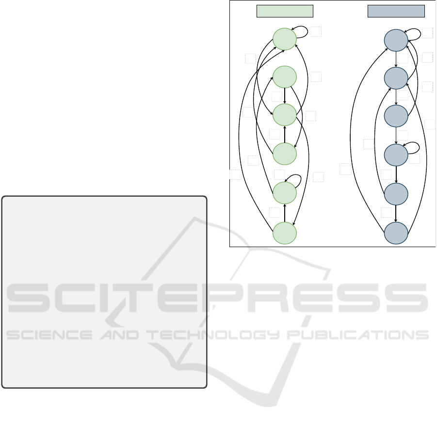
evolved circuit is shown in Fig 6.
Given the improvement we experienced using this
form of encapsulation, we then ran similar experi-
ments for each of the 4-bit and 5-bit SDs. For 4-
bit, the grammar was encapsulated with an individual
scoring 49,830, and the experiments were run with a
population size of 1,000, keeping all other settings the
same. A success of 30/30 is achieved in the result of
these experiments.
0/0
S0
S1
S2
S3
0/0
0/1
1/0
0/0
1/0
S4
1/0
0/0
S5
1/0
1/0
1/0
0/0
S0
S1
S2
S3
0/0
1/0
0/0
1/0
S4
1/0
S5
1/0
0/1
1/0
0/0
0/0
0/0
1/0
Evolved Circuit Gold Circuit
Figure 6: Comparison of gold vs evolved FSM of 6-bit
‘111000’ SD.
For 5-bit SD, the grammar was encapsulated with
an individual having a score of 49,897, and the exper-
iments were run with a population size of 1,000, keep-
ing all other settings the same. A success of 30/30 is
achieved in the result of these experiments. A com-
parison of all the results of experiments run with en-
capsulation is shown in Table 2.
Though encapsulation gave us a solution to 6-bit
SD, which we could only achieve with encapsulation,
the success rate is still much lower. We rerun the same
experiments for 6-bit SD with encapsulation but this
time with a population size of 3,000 and keeping all
other settings the same. We achieved the success rate
of 05/30, as shown in Table 2, which is a step up from
02/30 without the use of encapsulation. This demon-
strates that because extra resources increased perfor-
mance, the 02/30 experience in the earlier experiment
was not simply due to luck.
Table 4 compares our work with the literature in
terms of the evolutionary approach used, the number
of evolutionary stages used to evolve the circuit, the
sequence detectors evolved, the design type of HDL
code, and the number of individuals (evolutionary re-
sources) used. It can be seen in this comparison that
our work is the first ever to evolve the behavioural
level code of SDs using GE while using just one or
two evolutionary stages and comparatively far less
number of individuals.
Evolving Behavioural Level Sequence Detectors in SystemVerilog Using Grammatical Evolution
481
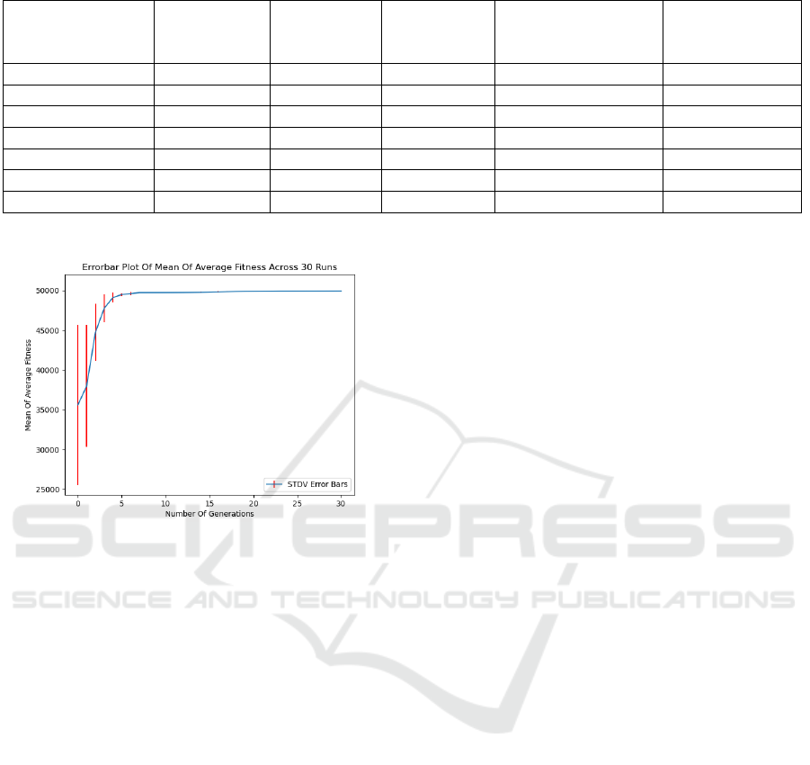
Table 4: Comparison with the state-of-the-art works.
Work
Evolutionary
approach
used
Number of
evolutionary
stages
SDs evolved Evolved design type
Number of
individuals used
for evolution
Ali et al., 2004 GA Four 4 and 6-bit Gate-level Upto 1 Million
Popa et al., 2005 GA Four 4 and 6-bit Gate-level 3,200
Yao et al., 2007 GA Three 3-bit Gate-level 11,500
Xiong et al., 2009 GA - 3-bit Gate-level 512,000
Tao et al., 2012 GA + GP Three 4 and 6-bit Gate-level -
This work GE One 3,4 and 5-bit Behavioral-level 30,000
This work GE Two 6-bit Behavioral-level 30,000
Figure 7: Mean of the average fitness across 30 runs of 6-
bit ‘111000’ evolution with pop. size of 3,000 and encap-
sulated grammar.
7 CONCLUSION AND FUTURE
WORK
This paper presents a tool to automatically design
sequential circuits, such as Sequence Detectors, us-
ing Grammatical Evolution as the evolutionary search
and mapping engine. As a result, 3-bit, 4-bit, 5-bit,
and 6-bit Sequence Detectors evolved successfully
using less number of stages and fewer computational
resources compared to the literature. Furthermore,
success rates of 30/30, 04/30, 01/30 and 05/30 (encap-
sulated) runs were achieved. The work presented here
is the first work of its kind using Grammatical Evolu-
tion, where the Hardware Description Language code
of Sequence Detectors is evolved directly to reach the
solution, which speaks for its novelty. It is planned to
extend this work to increase the search space in this
intuitive design of sequential circuits and evolve both
the current states and the subsequent states based on
the current inputs of the system. It is also thought to
increase the system’s complexity by moving toward
the evolution of multi-input single-output Sequence
Detectors.
ACKNOWLEDGMENTS
This work was supported by the Science Foun-
dation Ireland (SFI) grant 16/IA/4605. The fifth
author is also financed by the Coordenac¸
˜
ao de
Aperfeic¸oamento de Pessoal de N
´
ıvel Superior
- Brazil (CAPES), Finance Code 001, and the
Fundac¸
˜
ao de Amparo
`
a Pesquisa do Estado do Rio
de Janeiro (FAPERJ).
REFERENCES
Ali, B., Almaini, A. E. A., and Kalganova, T. (2004). Evo-
lutionary algorithms and theirs use in the design of
sequential logic circuits. Genetic Programming and
Evolvable Machines (GPEM), pages 11–29.
Ali, M. S., Kshirsagar, M., Naredo, E., and Ryan, C. (2021).
Towards automatic grammatical evolution for real-
world symbolic regression. In Proceedings of the 13th
International Joint Conference on Computational In-
telligence (IJCCI 2021).
Barros, M., Guilherme, J., and Horta, N. (2010). Analog
circuits optimization based on evolutionary computa-
tion techniques. Integration, 43(1):136–155.
Calvin, W. H. (1987). The brain as a darwin machine. Na-
ture, 330(6143):33–34.
CHU, P. P. (2008). Xilinx Spartan-3 Specific Memory, chap-
ter 12, pages 297–308. John Wiley and Sons, Ltd.
Ciletti, M. D. (2010). Advanced Digital Design with the
Verilog HDL. Prentice Hall Press, USA, 2nd edition.
Eagle (1988). Eagle by autodesk. https://www.autodesk.
com/products/eagle/overview. [Online; accessed 01-
Nov-2022].
Hemmi, H., Mizoguchi, J., and Shimohara, K. (1996).
Development and evolution of hardware behaviors.
In Sanchez, E. and Tomassini, M., editors, Towards
Evolvable Hardware (TEH), pages 250–265, Berlin,
Heidelberg. Springer Berlin Heidelberg.
Higuchi, T., Niwa, T., Tanaka, T., Iba, H., de Garis, H., and
Furuya, T. (1993). Evolving hardware with genetic
learning: A first step towards building a darwin ma-
chine. In From Animals to Animats 2: Proceedings of
ICAART 2023 - 15th International Conference on Agents and Artificial Intelligence
482

the Second International Conference on Simulation of
Adaptive Behavior, page 417–424. MIT Press.
Kalganova, T. (2000). An extrinsic function-level evolvable
hardware approach. In Poli, R., Banzhaf, W., Lang-
don, W. B., Miller, J., Nordin, P., and Fogarty, T. C.,
editors, Genetic Programming, pages 60–75, Berlin,
Heidelberg. Springer Berlin Heidelberg.
Kicad (1992). Kicad electronic design automation. https:
//www.kicad.org/. [Online; accessed 01-Nov-2022].
Lohn, J. D. and Colombano, S. P. (1998). Automated ana-
log circuit synthesis using a linear representation. In
Evolvable Systems: From Biology to Hardware, pages
125–133. Springer Berlin Heidelberg.
Manovit, C., Aporntewan, C., and Chongstitvatana, P.
(1998). Synthesis of synchronous sequential logic cir-
cuits from partial input/output sequences. In Evolv-
able Systems: From Biology to Hardware, page
98–105.
Mealy, B. and Tappero, F. (2018). Free Range VHDL. Free
Range Factory (2013); eBook (2018).
Miller, J. F. (2011). Cartesian Genetic Programming, pages
17–34. Springer Berlin Heidelberg, Berlin, Heidel-
berg.
Miller, J. F., Job, D., and Vassilev, V. K. (2000). Princi-
ples in the evolutionary design of digital circuits—part
i. Genetic Programming and Evolvable Machines,
1(1):7–35.
Mizoguchi, J., Hemmi, H., and Shimohara, K. (1994).
Production genetic algorithms for automated hard-
ware design through an evolutionary process. In Pro-
ceedings of the First IEEE Conference on Evolution-
ary Computation. IEEE World Congress on Computa-
tional Intelligence, pages 661–664 vol.2.
Murphy, A., Murphy, G., Amaral, J., Mota Dias, D.,
Naredo, E., and Ryan, C. (2021). Towards incorpo-
rating human knowledge in fuzzy pattern tree evolu-
tion. In European Conference on Genetic Program-
ming (Part of EvoStar), pages 66–81. Springer.
Navabi, Z. (2007). VHDL: Modular Design and Synthesis
of Cores and Systems. McGraw-Hill, New York.
Popa, R., Aiord
˘
achioaie, D., and S
ˆ
ırbu, G. (2005). Evolv-
able hardware in xilinx spartan-3 fpga. In Proceedings
of the 2005 WSEAS International Conference on Dy-
namical Systems and Control (ICDSC), page 66–71,
Stevens Point, Wisconsin, USA. World Scientific and
Engineering Academy and Society (WSEAS).
Ryan, C., Collins, J. J., and Neill, M. O. (1998). Gram-
matical evolution: Evolving programs for an arbitrary
language. In European Conference on Genetic Pro-
gramming, pages 83–96. Springer.
Ryan, C., Tetteh, M. K., and Dias, D. M. (2020). Be-
havioural modelling of digital circuits in system ver-
ilog using grammatical evolution. In IJCCI, pages 28–
39.
Shanthi, A., Singaram, L., and Parthasarathi, R. (2005).
Evolution of asynchronous sequential circuits. In
2005 NASA/DoD Conference on Evolvable Hardware
(EH’05), pages 93–96.
Solido (2005). Solido design solutions. https://eda.sw.
siemens.com/en-US/ic/solido/. [Online; accessed 01-
Nov-2022].
Spear, C. (2008). SystemVerilog for Verification, Second
Edition: A Guide to Learning the Testbench Language
Features. Springer Publishing Company, Incorpo-
rated, 2nd edition.
Stoica, A., Keymeulen, D., Zebulum, R., Thakoor, A.,
Daud, T., Klimeck, Y., Tawel, R., and Duong, V.
(2000). Evolution of analog circuits on field pro-
grammable transistor arrays. In Proceedings. The Sec-
ond NASA/DoD Workshop on Evolvable Hardware,
pages 99–108.
Tao, Y., Cao, J., Zhang, Y., Lin, J., and Li, M. (2012). Using
module-level evolvable hardware approach in design
of sequential logic circuits. In 2012 IEEE Congress
on Evolutionary Computation (CEC), pages 1–8.
Tetteh, M. K., Mota Dias, D., and Ryan, C. (2021). Evo-
lution of complex combinational logic circuits using
grammatical evolution with systemverilog. In Euro-
pean Conference on Genetic Programming (Part of
EvoStar), pages 146–161. Springer.
Xiong, F. and Rafla, N. I. (2009). On-chip intrinsic evolu-
tion methodology for sequential logic circuit design.
In 2009 52nd IEEE International Midwest Symposium
on Circuits and Systems, pages 200–203.
Yao, R., Wang, Y.-r., Yu, S.-l., and Gao, G.-j. (2007). Re-
search on the online evaluation approach for the dig-
ital evolvable hardware. In Evolvable Systems: From
Biology to Hardware (ESFBH), page 57–66, Berlin,
Heidelberg. Springer-Verlag.
Yao, X. and Higuchi, T. (1999). Promises and challenges of
evolvable hardware. IEEE Transactions on Systems,
Man, and Cybernetics, Part C (Applications and Re-
views), 29:87–97.
Youssef, A., Majeed, B., and Ryan, C. (2021). Optimizing
combinational logic circuits using grammatical evo-
lution. In 2021 3rd Novel Intelligent and Leading
Emerging Sciences Conference (NILES), pages 87–92.
IEEE.
Zebulum, R. S., Pacheco, M. A., and Vellasco, M. (1998).
Analog circuits evolution in extrinsic and intrinsic
modes. In Evolvable Systems: From Biology to Hard-
ware, pages 154–165. Springer Berlin Heidelberg.
Zhang, Y., Smith, S., and Tyrrell, A. (2004). Digital cir-
cuit design using intrinsic evolvable hardware. In Pro-
ceedings. 2004 NASA/DoD Conference on Evolvable
Hardware, 2004., pages 55–62.
Zhiwu, Z., Jian’an, L., Xinfeng, C., and Liming, Z. (2011).
Design of sequential logic circuits based on evolv-
able hardware. In IEEE 2011 10th International
Conference on Electronic Measurement Instruments
(ICEMI), volume 3, pages 240–243.
Evolving Behavioural Level Sequence Detectors in SystemVerilog Using Grammatical Evolution
483
