
Generation and Characterization of Fork Gratings in Fused Silica
Sebastian Buettner, Erik Thieme and Steffen Weissmantel
Laserinstitute Hochschule Mittweida, Technikumplatz 17, Mittweida, Germany
Keywords: Fork Grating, Orbital Angular Momentum, Fluorine Laser, Fused Silica, Calcium Fluorine Mask,
Micro Structuring, Micro Machining, Direct Laser Fabrication.
Abstract: Fluorine laser micro structuring enables the generation of fork gratings in fused silica. These micro-optical
elements can be used to influence the orbital angular momentum of light. This property of light has been
researched for more than 30 years and is becoming increasingly interesting for various applications. One of
them is optical data communication, where this can be used to increase the transmission capacity of optical
fibers. Now we have been able to demonstrate a simple fabrication method based on the fluorine laser micro
structuring technique, which allows us to generate different types of gratings. The results of our investigations
as well as those of the geometrical and optical characterization are presented.
1 INTRODUCTION
Electromagnetic (EM) fields are well understood
since Maxwell. The wavelength, polarization,
amplitude and phase are the common properties to
describe these fields. Each of mentioned can be
influenced and modulated by optical elements or
devices according to the requirements of the technical
application. In particular, the optical data
communication is based on the (de-)modulation of
these properties. This allows a simultaneous
transmission of optical signals. In the field of optical
data communication different, so called, multiplexing
methods were developed to increase the data rate. The
multiplexing methods, which, based on the
wavelength or polarization, cannot be developed
further due to the limited capacity of optical channels.
These limitations are caused by nonlinear effects, due
to the high intensities within the fibers (Richardson,
2010). One solution for this problem could be using
the orbital angular momentum (OAM) of EM fields
for multiplexing purposes (Xie et al., 2018 and
Bozinivic et al., 2013). However, the OAM is an
interesting property which also can be used for other
technical applications like optical tweezers. This
allows the rotation of microscopic particles by laser
light (Yao et al., 2011). Moreover, quantum optical
methods allow the entanglement of OAM states of
photons. This enables the development of new
techniques in the field of quantum optics (Mair et al.,
2001, Fickler et al. 2012 and Fickler et al., 2018). In
the last years several methods for micro-optics
fabrication were developed too, which allows the
miniaturisation and integration of micro-optics. First
and foremost, photolithography is a process for
creating highly precise microstructures. But the
process is expensive and time-consuming. Our
investigations show that we can fabricate irregular
micro-structures such as fork gratings in a much
easier way. For this we developed a fluorine laser
micro structuring method, which allows us to
generate individual grating geometries within a few
milliseconds. Moreover, we could show that these
gratings already can be used for OAM manipulation.
Accordingly, our process is verry suitable for an
efficient and flexible integration of these kinds of
optical elements and potentially for the development
of new communication hardware.
2 FUNDAMENTALS
In 1992 Les Allen and colleagues (Allen et al., 1992)
could show that electromagnetic fields include
angular momentum.
𝐽
⃗
=𝜖
𝑟
⃗
×(𝐸
⃗
×𝐵
⃗
)𝑑𝑟
(1)
Moreover, it is shown that the total angular
momentum is composed by the spin angular
momentum 𝑠⃗ and the orbital angular momentum 𝑙
⃗
.
The spin angular momentum (SAM) is associated
40
Buettner, S., Thieme, E. and Weissmantel, S.
Generation and Characterization of Fork Gratings in Fused Silica.
DOI: 10.5220/0011685500003408
In Proceedings of the 11th International Conference on Photonics, Optics and Laser Technology (PHOTOPTICS 2023), pages 40-45
ISBN: 978-989-758-632-3; ISSN: 2184-4364
Copyright
c
2023 by SCITEPRESS – Science and Technology Publications, Lda. Under CC license (CC BY-NC-ND 4.0)

with a circular polarization, whereas the orbital
angular momentum is resulting from a spatial
distribution.
𝐽
⃗
=
𝜖
2𝑖𝜔
𝐸
∗
(𝑟
⃗
×∇)
,,
𝐸
𝑑
𝑟
⃗
+
𝜖
2𝑖𝜔
𝐸
∗
×𝐸 𝑑
𝑟
⃗
(2)
More precisely, the orbital angular momentum
results from a helical phase shift, which, for example,
can be observed in Gaussian-Laguerre laser modes.
However, such a phase can also be induced by a phase
element that modulates an even EM field with an
amplitude 𝑢
(
𝑟,𝜑,𝑧
)
.
𝑢
(
𝑟,𝜑,𝑧
)
=𝑢
(
𝑟,𝑧
)
∙𝑒
∙𝑒
(3)
The expression 𝑒
describes an azimuthal
dependency of the phase, where 𝜑 is the azimuthal
angel and 𝑙 the topological charge (TC) (Allen et al.
2009 and 2011). There are several methods to induce
or influence the OAM of an EM field. As mentioned,
the Gaussian-Laguerre laser modes have an intrinsic
OAM which can be changed e.g., by a cylindrical
lens. Furthermore, it is possible to convert SAM to
OAM by anisotropic materials (Marrucci et al., 2006)
and q-plates (Karimi et al., 2009).
Back to the phase modulation, OAM can be
induced by optical elements like spiral phase plates
(SPP) or fork gratings (FG). These elements changing
the phase of an EM wave with an azimuthal
dependency. The phase shift results from an
azimuthal change of the optical thickness within a
transparent material. Due to the fabrication process
SPPs resemble a spiral staircase and can be generated
by changing the optical thickness of a substrate step
by step. In the case of SPPs, the TC defines the
number of 2π phase jumps within the structure, which
also represents the gear number of a helical
modulated wave front. The sign of 𝑙 gives the sense
of rotation of the phase, which is also called
handedness. Depending on the transition direction of
the optical elements, the handedness of the modulated
EM field is ether the same or inverted to the one of
the structures. Other than SPPs, FGs are a
superimposition of a helical phase and a grating
phase. Therefore, the helical phase is hidden within
the grating structure and can be recognized by the
ending grating bars and grooves within the structure.
The higher the TC, the more grating bars and grooves
ending within the structure.
FGs work slightly different relating to the OAM
modulation. In general, optical gratings bend the light
in one or more diffraction orders. Therefore, FGs
modulate and bend the light simultaneous and in a
different way for each diffraction order. The higher
the diffraction order, the higher is the OAM of these
order. Diffraction orders with an opposite sign also
show a different handedness, which is a result of the
law of conservation of momentum. For the generation
and examination of FGs, in addition to understanding
the function of the optical elements, their calculation
is necessary. The calculation of those gratings was
done using the numerical calculation software
Matlab
®
. Moreover, we basically follow the solution
of Galvez (Galvez E., 2016) to calculate the FG
layouts. The source code for calculation is given in
Table 1. In Figure 1 a) the calculated continuous
phase distribution of an FG with a TC of 1 is shown.
The developed fabrication process requires the
generation of a projection masks. For this, the phase
distribution must be converted into a binary, which is
done by a rounding operation (see Figure 1 b)). From
this, we can extract the grating geometry for the mask
generation.
Table 1: MATLAB
®
-Source for calculation of FGs.
N=500; l=1; n=10;
x=linspace(-N/2,N/2,N);
[X,Y]=meshgrid(x,x);
[phi,R]=cart2pol(X,Y);
bl=linspace(0,n*2*pi,N).*ones(N,N)
phase=round(mod(phi*l+bl,2*pi)/(2*pi));
Figure 1: Calculated phase distribution of a blazed fork
grating a) and its binary representation b).
Moreover, the knowledge of the micro structuring
depth is necessary for the FG generation. For a 2π
phase shift, the depth depends on the design
wavelength 𝜆 and the refractive indices of the
substrate 𝑛
and the continuum 𝑛
. It can be
calculated using equation 4.
ℎ=
𝜆
𝑛
−𝑛
(4)
For our investigations we used the fused silica
corning 7980. The refractive index of the material
a)
b
)
Generation and Characterization of Fork Gratings in Fused Silica
41
( 𝑛
= 1.4607 ) was calculated by the Sellmeier
equation for a wavelength of 𝜆= 532 𝑛𝑚. This leads
to a depth of ℎ = 1.1547 µ𝑚. It should be noted that,
unlike blaze gratings, binary gratings are ineffective
at a phase shift of 2𝜋. Therefore, the optimum phase
shift for binary FGs is at 𝜋, which corresponds to a
structure depth of ℎ = 0.577µ𝑚.
3 EXPERIMENTAL SETUP
The fluorine laser is very suitable for processing
fused silica and other wide band gap materials, due to
the short wavelength of 157 nm (7.9 eV). Moreover,
the used mask projection technique allows the
fabrication of different optical elements. The laser
machine and the appropriate processes are explained
detailed in earlier publications (Pfeifer M. et al. 2013,
2014, 2017 and Büttner S. et al. 2019, 2020).
Moreover, it is shown that this technology is very
flexible. By using different masks and micro
structuring methods a whole variety of micro-optical
elements can be fabricated. Recapped, there are three
options for processing material using the mask
projection technique: The movement of a mask within
the laser beam and static work piece, the movement
of the work piece and a static mask and an all-static
setup. Due to the laser source (Lambda Physics
LPF220i), the material is removed pulse by pulse.
The fabrication process depends on the target
microstructure, as well as the mask geometry, which
must be adapted too.
The process we developed consists of three steps,
the calculation of the grating geometry, the
generation of the mask by fluorine laser micro
structuring and the generation of the gratings. As
mask material we use calcium fluoride (CaF
2
) which
is transparent for the wavelength of the fluorine laser.
The treatment of the polished CaF
2
substrate surface
increases the roughness. Due to this, the transmitted
radiation is scattered in this area and the energy
density is reduced in the corresponding areas within
the image of the mask. As result, the mask geometry
is transferred into the workpiece. Based on the
calculation, the grating patterns were converted into a
machine program, which allows the fabrication of the
masks itself by fluorine laser micro structuring.
The generated pattern can be scaled up to the
required grating size. This should be done in
consideration of the feature size and the optical
resolution of the imaging system of the laser machine.
The up and down scaling is useful for adjusting the
optical properties of the grating. To show the
possibilities of this technique we calculated and
generated five different masks in an CaF
2
substrate
(see Figure 2). This technique currently allows the
generation of binary structures only, but contrary to
using tantalum masks, the layout of the masks in CaF
2
can be individual without compromising of the
mechanical stability of the mask.
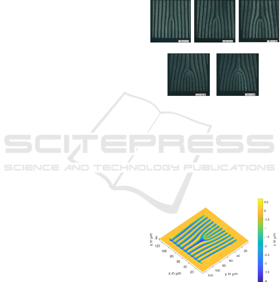
Figure 2: Calcium fluoride masks for the fabrication for
fork gratings with a TC of 𝑙 = 1,2,3,4,5 {a), b), c), d), e)}.
4 RESULTS
As mentioned above, we used a static mask design for
grating generation. In addition to the CaF
2
grating
masks, a 100 x 100 µm² square tantalum mask was
used to expose only the corresponding patterned areas
of the grating masks to laser radiation. A Slight
misalignment of the tantalum and the grating mask
leads to structuring errors, as can be seen in Figure 3.
Figure 3: Confocal image of an FG in fused silica Corning
7980.
By using a larger tantalum mask the area
surrounding the grating can be lowered such as the
grating is exposed. Contrary to expectations, the
analysis of the produced structures shows that the
a)
b
)
c)
d)
e
)
PHOTOPTICS 2023 - 11th International Conference on Photonics, Optics and Laser Technology
42
lattice is not binary at all (see Figure 4). The shape of
the grating profile section becomes more sinusoidal
with increasing number of laser pulses. The grating
bars were also influenced by the laser radiation.
Therefore, the function of the CaF
2
masks differs
from that of the tantalum masks. As can be seen in
Figure 5, up to 20 pulses, the depth of the
microstructure depends linearly on the number of
laser pulses. A further increase of the number of
pulses does not increase the depth of the grooves.
Therefore, the total depth of the micro structuring is
limited.
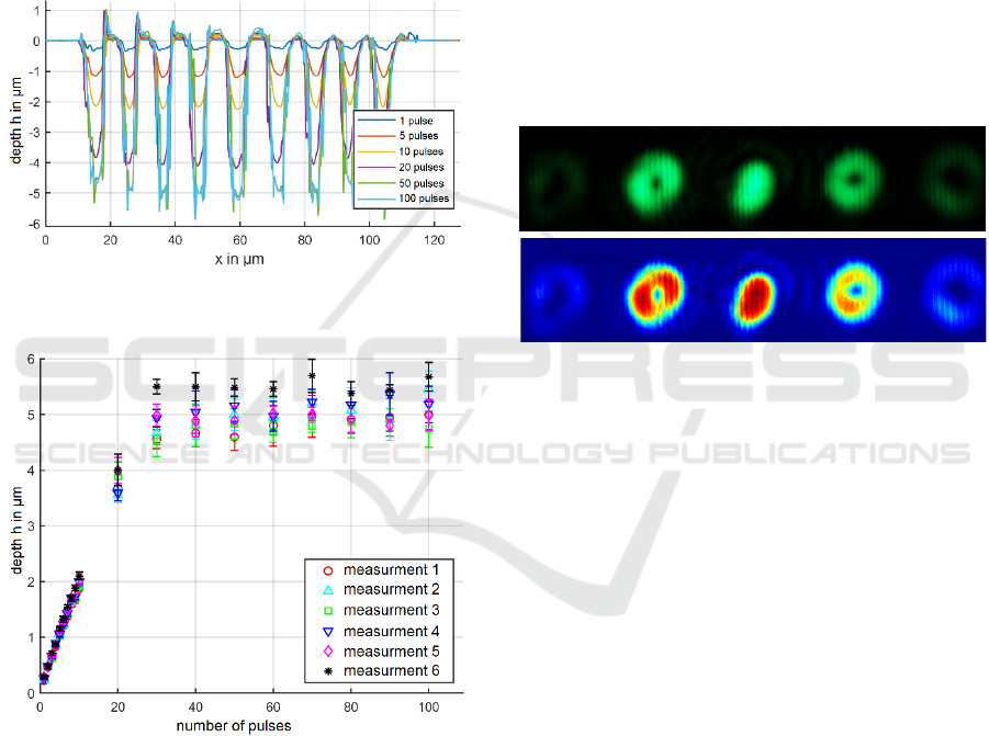
Figure 4: Profile section of the FGs fabricated with different
numbers of laser pulses.
Figure 5: Micro structuring depth depending on the number
of laser pulses for different locations within one FG.
For each grating type, this linear dependence was
observed up to 20 laser pulses. The maximum depth,
on the other hand, depends on the laser pulse fluence
and the corresponding ablation depth per pulse. In
general, the laser power, the efficiency of the imaging
system and the optical parameters of the mask
material are the main limiting factors. According to
this, a maximum structure depth of 5 µm was reached
on average. The period of the grating was set to
20 µm, which results in a feature size of around
10 µm. Therefore, the aspect ratio is limited to a
maximum of 2:1. Moreover, the increase of the
number of pulses, the grating bars getting higher than
the initial surface by the ablation process. This can be
explained by the redeposition of material in the areas
not having been exposed to radiation. It is currently
unclear what the fine structure and optical properties
of the redeposited material are, but the influence of
the geometry deviations on the function should be
significantly stronger. Furthermore, we observed the
diffraction image of the gratings, using a microscope
and an appropriate laser source for the backside
illumination of the optical elements. One diffraction
image is shown in Figure 6 a). To see differences in
the intensity more clearly, we calculated a colored
representation b) of the image.
Figure 6: Microscopic diffraction image a) and colored
representation b) of the diffraction image of an FG {𝑙=1,
ℎ =0.540 µ𝑚}.
The FG work as expected. Due to the shape of the
grating the intensity is mainly diffracted to the 0
th
and
the ± 1
st
diffraction orders. The 0
th
order does not
show any OAM modulation contrary to the higher
orders. The modulated diffraction orders show the
typical circular shaped intensity distribution of beams
with OAM. Moreover, the radius of the distributions
increases with the number of the diffraction order due
to the increase of the OAM. As can be seen, the radius
of 2
nd
diffraction orders is larger than the one of the
1
st
. The ± 2
nd
diffraction orders are also visible, but
the intensity is significantly lower as can be seen.
Moreover, the comparison of the + 1
st
and - 1
st
diffraction orders show a slight difference in the
intensity distribution. This can be explained by the
slightly asymmetric shaped slopes of the grating bars
(see Fig 7). Furthermore, the grating grooves are not
even, which resulted from a misalignment of the
workpiece related to the imaging plane of the optical
system. This can be easily corrected but it may also
be used to generate defined grating slopes.
Finally, controlling the slope angel opens the
opportunity to fabricate blazed gratings using this
technique and motivates further investigations.
a)
b
)
Generation and Characterization of Fork Gratings in Fused Silica
43
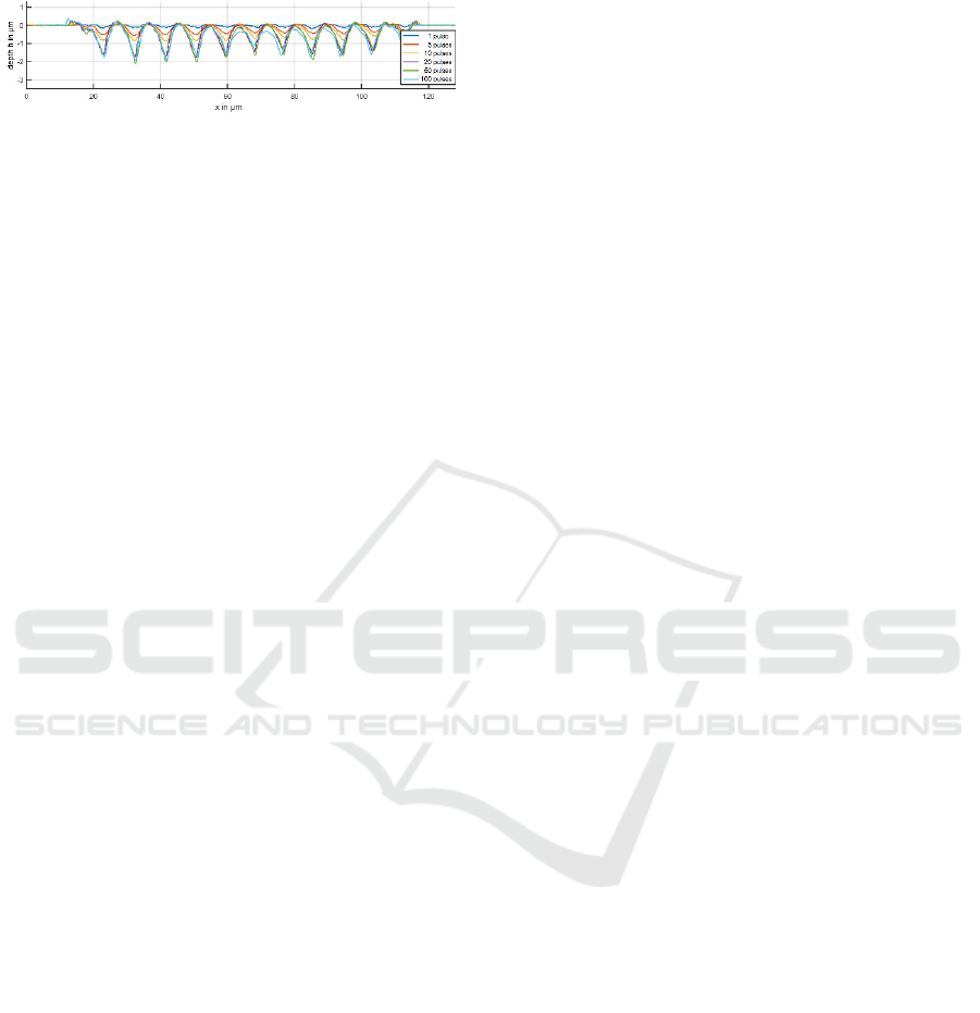
Figure 7: Profile sections of the FGs { 𝑙=1}
fabricated with different numbers of laser pulses.
5 CONCLUSIONS AND
OUTLOOK
For the fabrication of FG’s, a new method was
developed. The process is based on the fluorine laser
micro structuring and uses the mask projection
technique. The first step is the calculation of the
grating pattern and generation of a machine program
thereof. Following, the grating layout is transferred
into a VUV grade CaF
2
substrate using fluorine laser
micro structuring. The VUV grade CaF
2
is
transparent for 157 nm radiation, but in the laser
treated areas the roughness and therefore the
scattering of the radiation is increased. Due to this,
the substrate can be used as amplitude mask itself and
an individual geometry can be transferred into a fused
silica substrate. This was done using different
numbers of laser pulses. We could show that the
structure depth depends linear on the number of
pulses until 20 laser pulses. For more than 20 pulses
the depth of the structures does not increase further.
Moreover, the structure depth is limited and a
maximum aspect ratio of 2:1 can be reached. This
represents a limit in feature size range regarding to
the target modulation depth. Furthermore, it could be
shown that the FG work as expected. The diffraction
image shows diffraction orders up to the ± 2
nd
order.
The asymmetric distribution of intensity is a result
from the asymmetric slopes of the grating bars. The
reason for this is a slightly misalignment between
image plain and surface of the work piece, which
easily can be corrected. But potentially this could also
be used to generate blazed FG. In general, we could
show that the generation of FG’s work well and the
optical function satisfy our expectations. To improve
this, the generation of blazed FG is the next goal of
our investigations. An easy and flexible fabrication
method for blazed FG’s could push forward the OAM
multiplexing method due to new possibilities in
production of OAM multiplexing hardware.
REFERENCES
Richardson, D. J. (2010). Filling the Light Pipe. In: Science,
330 (6002), pp. 327-328.
Xie, Z.; Gao, S.; Lei, T.; Feng, S.; Zhang, Y.; Li, F.; Zhang,
J.; Li, Z.; Yuan, X. (2018). Integrated (de)multiplexer
for orbital angular momentum fiber communication. In:
Photonics Research, 6(7), pp. 743-749.
Bozinivic, N.; Yue, Y.; Ren, Y.; Tur, M.; Kristensen, P.;
Huang, H.; Willner, A.E.; Ramachandran, S. (2013).
Terrabit-Scale Orbital Angular Momentum Mode
Division Multiplexing in Fibers. In: Science,
340(6140), pp. 1545-1548.
Yao, A.M.; Padgett, M.J. (2011). Orbital Angular
Momentum: origins, behaviour and applications. In:
Advances in Optics and Photonics, 3, pp. 161-204.
Mair A.; Vaziri, A.; Weihs, G.; Zeilinger, A. (2001).
Entanglement of the orbital angular momentum states
of photons. In: Nature, 412, pp. 313-316.
Fickler, R.; Lapkiewicz, R.; Plick, W. N.; Krenn, M.;
Schaeff, C.; Ramelow, S.; Zeilinger, A.
(2012). Quantum Entanglement of High Angular
Momenta. Science, 338(6107), 640–643. doi:10.1126/
science.1227193
Fickler, Robert; Krenn, Mario; Zeilinger, Anton
(2018). Mit Lichtschrauben ans Quantenlimit. Physik
in unserer Zeit, 49(1), –. doi:10.1002/piuz.201801494
Allen, L.; Beijersbergen, M.W.; Spreeuw, R.J.C.;
Woerdman, J.P. (1992). Orbital angular momentum of
light and the transformation of Laguerre-Gaussian laser
modes. In: Physical Review A, 45(11), pp. 8185-8189.
Allen, L.; Padget, M. (2011). The Orbital angular
momentum of light. In Twisted Photons, WILEY-VCH
Verlag GmbH, pp. 1-12, Weinheim.
Marrucci, L.; Manzo, C.; Paparo, D. (2006). Optical Spin-
to-Orbital Angular Momentum Conversion in
Inhomogeneous Anisotropic Media. Physical Review
Letters, 96(16), 163905 doi:10.1103/PhysRevLett.
96.163905
Karimi, Ebrahim; Piccirillo, Bruno; Nagali, Eleonora;
Marrucci, Lorenzo; Santamato, Enrico
(2009). Efficient generation and sorting of orbital
angular momentum eigenmodes of light by thermally
tuned q-plates. Applied Physics Letters, 94(23),
231124–. doi:10.1063/1.3154549
Pfeifer, M.; Weissmantel, S.; Reisse, G. 2013. Direct laser
fabrication of blaze gratings in fused silica. In: Applied
Physics A, 112(1), pp. 61-64.
Pfeifer, M.; Jahn, F.; Kratsch, A.; Steiger, B.; Weissmantel,
S. 2014. F2-Laser Microfabrication of Diffractive
Optical Elements. In: Proceedings of 2nd International
Conference on Photonics, Optics and Laser
Technology, pp. 91-96.
Pfeifer, M.; Büttner, S.; Zhang, R.; Serbay, M.;
Weißmantel, S. (2017). F2-Lasermikrostrukturierung
von Mikro-Fresnel-Linsen, In: Scientific Reports,
10. Mittweidaer Lasertagung, (2), pp. 127-130.
Büttner, S.; Pfeifer, M.; Weissmantel, S. (2019).
Manufacturing of Cylindrical Micro Lenses and Micro
PHOTOPTICS 2023 - 11th International Conference on Photonics, Optics and Laser Technology
44

Lens Arrays in Fused Silica and Borosilicate Glass
using F2-Laser Microstructuring. In: Proceedings of 7th
International Conference on Photonics, Optics and
Laser Technology, pp. 66-72.
Büttner, S.; Pfeifer, M.; Weissmantel, S. (2020).
Fabrication of Micro Spiral Phase Plates in Fused Silica
using F2-Laser Microstructuring. In: Proceedings of 8th
International Conference on Photonics, Optics and
Laser Technology, pp. 114-121.
Galvez, E.: Computer Program FORKED DIFFRACTION
PATTERN, Version 1.0 (2016), WWW Document:
(http://departments.colgate.edu/physics/gpl.htm).
Generation and Characterization of Fork Gratings in Fused Silica
45
