
Imaging System Front-End at 202GHz Using LO/RF Isolation of
Harmonic Mixer for Illumination
Abdorreza Torabi
a
School of Engineering Science, College of Engineering, University of Tehran, Tehran, Iran
Keywords: Millimeter-Wave Imaging, Harmonic Mixer, LO/RF Isolation, Horn Antenna, Cassegrain Mirror, Field of
View, Concealed Object.
Abstract: A millimeter-wave imaging system front-end at 202 GHz is developed and presented. To have more compact
and economical transceiver and also due to the finite isolation between the LO and RF ports, a commercial
harmonic mixer acts both as receiver and transmitter. To improve the performance as well as imaging quality
an optomechanical system with ray optics designed configuration of mirrors is presented. Results of the 202
GHz imager for stand-off detection at 2.5m are illustrated.
1 INTRODUCTION
Active radio frequency imaging is utilized in two
main applications; radar cross section (RCS) and
concealed target objects detection. In RCS the wave
reflectivity of desired target is considered, while in
imaging applications of detection, the target objects
are obscured by one or more barriers which are not
transparent (Collins, et al. 1995). Active millimeter
wave (mm-wave) imaging typically points to
frequency range of 30GHz-300GHz (may also
includes lower microwave frequencies (Collins, et al.
1995, Huguenin, et al. 1993, Sheen, et al. 2001,
Sheen, et al. 2010)) is a topic of research interest due
to facts that X-ray or other ionizing radiation imaging
vehicles turns to be inconvenient, unsafe or
ineffective in some practical situations.
Active mm-wave imaging systems are capable of
penetrating common clothing and form an image of
concealed targets like weapons (Appleby and
Anderton, 2007) as well as a person's body.
Moreover, relatively short wavelength of these
systems, high resolution images can be achieved.
Several commercial mm-wave imaging systems have
been presented (TS4 and TS5 by Thruvision, Gen2 by
Brijot). Recent effort lies in developing cost effective
compact and robust systems to be used in the field of
such as airports (García-Rial, et al. 2019).
a
https://orcid.org/0000-0002-0016-9979
Cold sky radiation is the main source of contrast
for passive imagers at outdoor scenarios, make them
useful to detect and image the thermal emission of the
scene. Furthermore, the amount of attenuation for
passive millimeter wave radiation in poor weather
conditions like fog, snow, rain, dust is less than for
visual or infrared radiation in orders of magnitude
(Spinoulas, et al. 2012). However, at indoor
environment, absence of cold sky radiation make
imager to have higher sensitivity. This requirement
renders passive imagers made for indoor scenarios to
have lower imaging speed and higher overall cost.
One possible solution is to make use of active
illumination of the scene in order to create
radiometric contrast between objects of interest
(Sheen, et al. 2010). Bryllert et al. have developed a
transceiver module for a 3-D imaging radar at 220
GHz that consists of a frequency doubler which also
acts as a subharminic mixer (SHM) based on GaAs
semiconductor membrane technology (Bryllert, et al.
2013). Tang used infrared laser illumination along
with a passive mm-wave imager in order to enlarge
the radiometric contrast between different objects and
background (Tang, 2016). Petkie et al. developed an
imaging system at 640 GHz and concluded that active
mm-wave imaging systems can have large dynamic
ranges even with moderate illumination power
compared to passive imaging (Petkie, et al. 2008).
74
Torabi, A.
Imaging System Front-End at 202GHz Using LO/RF Isolation of Harmonic Mixer for Illumination.
DOI: 10.5220/0011685400003408
In Proceedings of the 11th International Conference on Photonics, Optics and Laser Technology (PHOTOPTICS 2023), pages 74-77
ISBN: 978-989-758-632-3; ISSN: 2184-4364
Copyright
c
2023 by SCITEPRESS – Science and Technology Publications, Lda. Under CC license (CC BY-NC-ND 4.0)
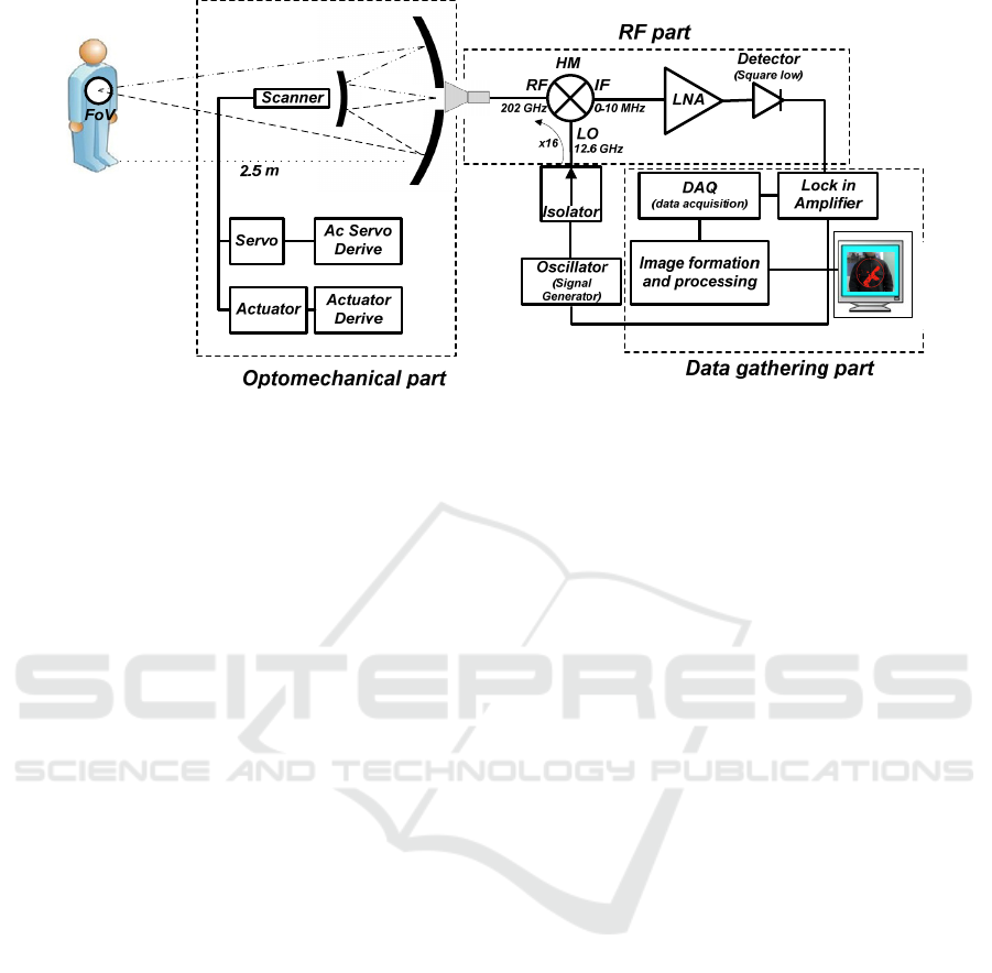
Figure 1: Block diagram of the implemented imager at 202GHz.
Canavero et al. have investigated most
applicable/suitable type of illumination source for
producing images with enhanced contrast and details
for W band imaging systems at indoor environments
(Canavero, et al. (2013). Finally, Grajal et al. have
demonstrated a stand-off imaging system
incorporating a compact front-end radar at 300 GHz
in which a commercial-of-shelf (COTS) SHM is used
as a transceiver (Grajal, et al. 2017).
In this paper active mm-wave imaging system at
202GHz with the use of COTS harmonic mixer for
both illuminating the scene and receiving the
reflected wave due to finite isolation between mixer's
LO and RF ports is presented. Using mono-static
power relation for desired configuration minimum
required antenna gain is derived for given minimum
detectable signal to noise ratio (SNR), noise
equivalent power (NEP) of the receiver and selected
harmonic mixer. To provide required radiation gain,
a cassegrain antenna configuration with focusing
point of the reflector system at 2.5m from front is
implemented to improve the performance of the
radiation of the horn antenna. A scanning system
including a scanner and secondary inclinating and
rotating mirror is used to spirally scan of the desired
field of view (FoV). The main advantages of the
proposed system are lower cost compared to
conventional active imaging systems, simple
hardware architecture and compactness due to
integration of transmitter and receiver modules. To
exclude very noise frequency noise like Flicker noise
contribution, amplitude (AM) modulation of the LO
signal is used. The results of the imaging show
excellent performance of the presented mm-wave
imager.
2 SYSTEM ARCHITECTURE
AND ACTIVE MODE
COMPUTATIONS
The mm-wave imager is a total power radiometer in
202 GHz frequency band. Block diagram of the mm-
wave imager is shown in Figure 1 which consists of
RF part including transceiver system,
optomechanical part including cassegrain mirror and
scanning system and finally data gathering part
including data acquisition and image formation and
processing.
In RF part, a scalar horn antenna with 10 dB gain
at boresight direction is considered. Harmonic mixer
of Radiometer Physics (RPG FS-Z220) is used which
works in 16
th
LO harmonic number with LO
frequency 12.6 GHz and LO power of 15 dBm which
is provided by Signal Generator HP8340. RF to IF
conversion loss is 30dB and nearly 26dB isolation
between LO/RF is measured and used in
computations. Down converted signal at IF frequency
amplified with the use of typical low noise amplifiers
so that the signal power reaches detection limit of
square low detector (HP 8474E). A function
generator is used to AM modulate the signal deriving
mixer’s LO port. A lock-in amplifier synchronized to
the LO modulating signal to detect the down-
converted signal buried in large background noise.
System noise temperature is given by
s
ys rec A
TTT=+
(1)
where
rec
T and
A
T are receiver and antenna noise
equivalent temperature respectively. The antenna
noise temperature is typically negligible compared
Imaging System Front-End at 202GHz Using LO/RF Isolation of Harmonic Mixer for Illumination
75

to the receiver noise temperature. For
rec
T we have
I
Frec M M
L
TTT+= (2)
where
M
T is mixer noise temperature,
M
L
is RF to
IF conversion loss factor and
I
F
T is LNA noise
temperature.
Using overall system noise temperature, noise
equivalent power (NEP) of the system at the specified
bandwidth
B
(10 MHz is considered) is given by:
sys
NEP kT B=
(3)
where k is the Boltzmann constant. Typically, mLO
to RF leakage in passive radiometer is regarded
undesirable. In this work we make use of the mLO
(m=16) to RF leakage as an additional means to the
mm-wave imaging system to illuminate the scene and
therefore configure an active mm-wave imager. The
resulting active image can serve an additional
information besides the primary passive image
(García-Rial, et al. 2019, Grajal, et al. 2017). In this
way, this setup represents a mono-static configuration
in which a single antenna is used for both illuminating
the scene and receiving the reflected waves. In order
to get a detection criterion in active mode, utilizing
mono-static radar equation and assuming that the
receiver is able to detect only vertical polarization:
()
22 02
max
3
4
4
ap
rt
G
P
P
R
εσλ
π
=
(4)
where
0
σ
is backscatter coefficient,
max
G
is the
antenna gain boresight direction (neglecting
sidelobes contributions),
λ
is free space wavelength,
R
is the distance of object and antenna and
t
P is
radiated power from the antenna and
ap
ε
is the
efficiency of the antenna aperture (typical: 80%). By
assuming
s
ource
P as derive power at LO port of mixer
and
/mLO RF
I as isolation factor of LO/RF ports, we
have
/tsourcemLORF
PPI= . Then the received power
r
P
should be satisfied inequality;
r
PNEP≥Ω , where
Ω
is the minimum detectable SNR. Substituting from
the equation derived above we have:
()
22 02
max
/
3
4
4
ap
source mLO RF sys
G
P
IkTB
R
εσλ
π
≥Ω
(5)
To help inequality (5) to be established one can make
the right side of (5) as small as possible and the left
side as large as possible. For selected harmonic mixer
as well as other harmonic mixers,
/
s
ource mLO RF
PI has its
own certain amount and does not have much changes.
Smaller
s
ys
T
required more sensitive and low noise
receiver which directly increase the total cost of the
system. But an efficient approach to have smaller
minimum detectable SNR is AM modulating of the
LO signal and making IF detector synchronized with
it (Figure 1). Frequency of modulation can be chosen
in [200KHz-800KHz] for
10MHzB = . Therefore
very low frequency noise sources like Flicker noise
would not contribute and make
Ω
smaller. In the left
side of (5), it is focused on the
max
G
. As illustrated in
Figure 1 and 2, a cassegrain antenna configuration is
used to redirect the incoming radiation from the scene
into the horn. This configuration has a circular field
of view (FoV) of 40cm in diameter focusing point of
the reflector is set at a distance of 2.5m from the front
panel. The location of the horn and the parameter of
two reflecting mirrors, are designed using ray optics
relations. The scanning of the FoV is performed via
synchronized rotation and inclination of the
secondary mirror which provides spiral scanning of
the scene. It is proved that this configuration of
optical mirrors with horn located in the aperture
(Figure 2) makes the main lobe of radiation pattern of
the horn more directive and conclusively improve
max
G
.
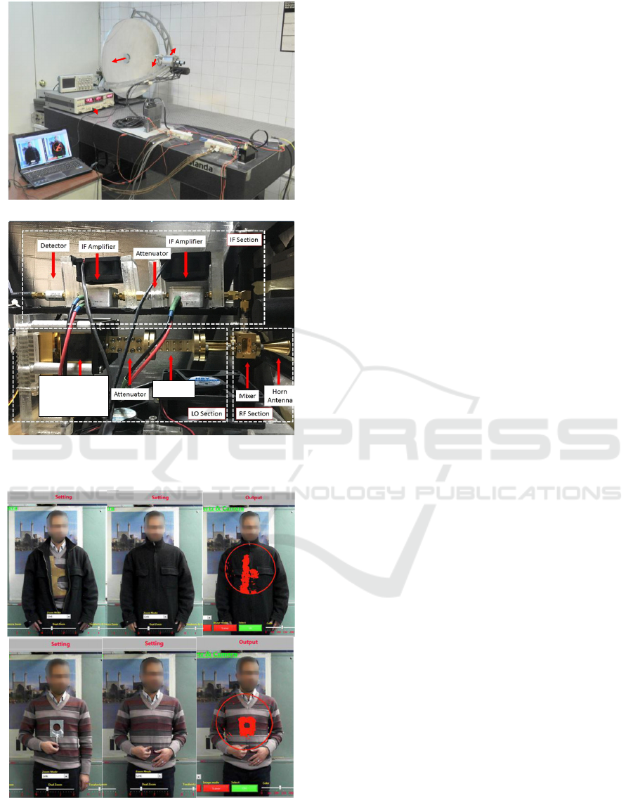
3 RESULTS
Figure 3 shows indoor experimental results of the
implemented mm-wave imaging system at 202 GHz.
They show someone standing at 2.5m in front of the
system with concealed metallic gun simulator and
pierced plate which their images are appropriately
formed and perfect detection is done with the use of
active illumination of power leakage LO/RF of the
mixer.
4 CONCLUSION
In this paper, with the use of finite isolation between
mixer's LO and RF ports for illuminating the scene,
active mm-wave imaging system at 202GHz is
presented. An optomechanical system with ray
optics designed configuration of mirrors is also
presented. Stand-off imaging of the target in 2.5m
PHOTOPTICS 2023 - 11th International Conference on Photonics, Optics and Laser Technology
76
Mirror 1
fixed
Mirror 2
Rotation-inclination
Scanner
Image formation
Lock in Amp
Horn
Antenna
(a)
Scalar horn
Power Source
12.6 GHz
Isolator
(b)
Figure 2: (a) Front and (b) behind view of the imager.
Figure 3: Results of imaging at 202 GHz with proposed
imager, metallic gun simulator and metallic pierced plate.
is implemented with scanning system including a
scanner and inclinating/rotating mirror. Such a
configuration of mirrors improve the gain of the horn
antenna located on the aperture of the system due to
dual reflection mechanism to satisfy the mono-static
radar equation required for detection. The results of
the imaging show excellent performance of the
presented mm-wave imager.
REFERENCES
Collins, H., et al. (1995). For near real-time holographic
imaging of a target. http://www.google.com/
patents/US5455590, US Patent 5,455,590.
Huguenin, G., et al. (1993). Contraband detection system.
http://www.google. com/patents/US5227800, US
Patent 5,227,800.
Sheen, D., McMakin, D., Hall, T. (2001). Three-
dimensional millimeter-wave imaging for concealed
weapon detection, IEEE T Microw Theory 49, no. 9,
1581–1592.
Sheen, D., McMakin, D. and Hall, T. (2010). Near-field
three-dimensional radar imaging techniques and
applications, Appl Opt 49, no. 19, E83–E93.
Appleby, R., Anderton, R. (2007). Millimeter-Wave and
Submillimeter-Wave Imaging for Security and
Surveillance, Physics, Proceedings of the IEEE, vol. 97,
no. 8, pp. 1683-1690.
García-Rial, F., et al. (2019). Combining Commercially
Available Active and Passive Sensors Into a
Millimeter-Wave Imager for Concealed Weapon
Detection, Microwave Theory and Techniques IEEE
Transactions on, vol. 67, no. 3, pp. 1167-1183.
Spinoulas, L., et al. (2012). Optimized compressive
sampling for passive millimeter-wave imaging, Appl
Opt 51, no. 26, 6335–6342.
Bryllert, T., et al. (2013). Integrated 200-240-GHz FMCW
radar transceiver module,” IEEE Trans. Microw.
Theory Techn., vol. 61, no. 10, pp. 3808–3815.
Tang, A. (2016) "System level challenges of THz and mm-
wave imaging systems", Proc. SPIE 9836, Micro- and
Nanotechnology Sensors, Systems, and Applications
VIII.
Petkie, D., et al. (2008). Active and passive imaging in the
THz spectral region: Phenomenology, dynamic range,
modes, and illumination, J. Opt. Soc. Am. B, Vol. 25,
No. 9.
Canavero, M., et al. (2013). Radiometric Active Indoor
Imaging in the W-Band, Journal of Infrared millimeter,
and terahertz, 35(2), pp. 218-241.
Grajal, J., et al. (2017) Compact Radar Front-End for an
Imaging Radar at 300 GHz”, IEEE Transactions on
Terahertz Science and Technology, vol. 7, no. 3, pp.
268 – 273.
Imaging System Front-End at 202GHz Using LO/RF Isolation of Harmonic Mixer for Illumination
77
