
A Modelling Methodology for Developing an Information Model for
Cyber-Physical Production Systems using OPC UA
Mainak Majumder
1
and Alois Zoitl
2
1
LIT CPS Lab, Johannes Kepler University, Linz, Austria
2
CDL VaSiCS, LIT CPS Lab, Johannes Kepler University, Linz, Austria
Keywords:
CPPS, Information Model, Industry 4.0, Model-Driven Architecture, OPC UA.
Abstract:
The Open Platform Communication Unified Architecture (OPC UA), due to its sophisticated information
modelling mechanism, has emerged as one of the principal tools for developing information models of Cyber-
Physical Production Systems (CPPS). However, developing information models, especially for legacy brown-
field systems, remains a challenging task. This is due to the unavailability of adequate modelling techniques
as well as a higher learning curve regarding the OPC UA model. Therefore, the goal of this paper is to analyse
the OPC UA information modelling paradigm and propose a generic technology-agnostic modelling method-
ology that could act as a guideline for OPC UA information model development.
1 INTRODUCTION
Cyber-Physical Production Systems (CPPS) require
machines on the shop floor to communicate and share
information with each other as well as with high-
level Enterprise Resource Planning (ERP), Cloud ap-
plications (Buchgeher et al., 2022). However, seam-
less machine-to-machine communication in CPPS re-
mains a challenge due to the data heterogeneity on
the shop floor. This challenge could be addressed
by using a standardized technology-agnostic infor-
mation model of CPPS as a layer of interoperability.
This should enable seamless communication and in-
formation exchange among the heterogeneous shop
floor machines as well as between shop floor and
MES/ERP/Cloud applications (Vogel-Heuser et al.,
2009). The Open Platform Communication Unified
Architecture (OPC UA) could provide the interoper-
ability layer via its information models.
OPC UA is a platform-independent vendor-
agnostic middleware solution developed for industrial
automation (Mahnke et al., 2009). Information mod-
elling is one of the important features of OPC UA.
It provides a standard meta-model for information
model development (OPC Foundation, 2021). For se-
mantic interoperability between OPC UA and exist-
ing automation standards, OPC UA provides multiple
domain-specific models (also called companion spec-
ifications e.g. PLCopen (OPC Foundation, 2020a)).
However, information modelling not being a familiar
concept in Operation Technology (OT), could make
the development of OPC UA information models, es-
pecially for brownfield legacy systems, a challenging
task. The modeller should not only be well-versed in
the OPC UA modelling standards but also should be
able to understand the concepts relevant to the OT do-
main.
OPC UA, being a relatively new technology, im-
poses a steep learning curve. A generic methodol-
ogy describing the workflow of the model develop-
ment process could be helpful to the model devel-
oper to overcome the learning curve and reduce mod-
elling effort. Apart from that, it can also be used
as a guideline to separate the tasks involved in the
modelling process, assign roles to different people in-
volved in the modelling process, and generate docu-
mentation. While the OPC UA standard provides a
set of rules and regulations regarding modelling tech-
niques, it doesn’t provide any modelling methodolo-
gies that can be used as best practices.
Therefore, the primary goal of this paper is to de-
velop a conceptual methodology based on the OPC
UA modelling paradigm that could be used as a guide-
line for model development. The rest of the paper
is organized as follows. Section 2 discusses existing
works in the field of OPC UA information model de-
sign and Section 3 provides a detailed analysis of the
OPC UA modelling paradigm. Section 4 describes as-
sociated challenges in the information model develop-
ment process using an example use-case. In Section
152
Majumder, M. and Zoitl, A.
A Modelling Methodology for Developing an Information Model for Cyber-Physical Production Systems using OPC UA.
DOI: 10.5220/0011684900003402
In Proceedings of the 11th International Conference on Model-Based Software and Systems Engineering (MODELSWARD 2023), pages 152-159
ISBN: 978-989-758-633-0; ISSN: 2184-4348
Copyright
c
2023 by SCITEPRESS – Science and Technology Publications, Lda. Under CC license (CC BY-NC-ND 4.0)

5, the proposed methodology is described. Finally,
Section 6 concludes the paper.
2 RELATED WORKS
Pauker et al. in (Pauker et al., 2016) describe an
MDA-based modelling approach for developing the
OPC UA information model. The process involves
creating a Computation-Independent Model (CIM)
first that provides an abstract overview of the system.
After that, CIM is used to generate Platform Inde-
pendent Model(s) (PIMs) that describe the structural
and behavioural components. Additionally, OPC UA-
based restrictions are included in PIMs and restricted
PIMs (R-PIMs) are developed. Overall, the paper
provides a straightforward approach without delving
into the details of individual steps. However, Uni-
fied Modelling Language (UML) is primarily used
for modelling CIM, PIM, and R-PIM and the model
transformation process was the primary concern of
the paper. Apart from that, this approach also doesn’t
take into consideration the usage of existing compan-
ion specifications for model development. The UML
to OPC UA model transformation approach is pro-
vided by the same author in (Pauker et al., 2018).
Rohjans et al. in (Rohjans et al., 2013) described
a method of generating OPC UA information mod-
els for power systems via UML model transformation.
The approach takes existing data models (e.g. Com-
mon Information Model (CIM) or IEC 61850) and
generates a UML representation. After that, a model
transformation is performed based on the UML OPC
UA profile. Similar work regarding UML to OPC
UA model transformation is also done by authors in
(Lee et al., 2017). The paper provides a generic
mapping of UML elements to OPC UA and used
Query/View/Transformation (QVT) for model trans-
formation. However, UML is mainly used for meta-
model development that lacks semantic integrity. The
authors mentioned that this issue could be addressed
by developing a set of standard ontology. However,
no further exploration in that direction is done in the
paper.
In (Schmied et al., 2021), authors proposed an
information modelling approach for manufacturing
shop floors with a high number of end products. The
authors also acknowledge that there exist no specific
guidelines on identifying necessary domain informa-
tion of a manufacturing system and translating them
to OPC UA models. Therefore, the authors used
SIPOC (Supplier, Input, Process, Output, Customer)
analysis to identify the data points which are con-
verted to OPC UA Objects (Toutenburg and Kn
¨
ofel,
2008). Regarding integrating existing standards, the
authors mentioned that there are some missing re-
quirements which can’t be covered by existing infor-
mation models which is why company-specific mod-
els are developed. However, the paper didn’t specify
rules for identifying and utilising existing compan-
ion specifications along with their company-specific
information model. Apart from that, the authors
also used their own terminologies for developing a
company-specific information model.
In general, there exist a general gap in research
regarding the OPC UA model development process.
While the above-mentioned research works used ex-
isting model development methodologies in order to
address this research gap, none of the approaches pro-
vides a generic approach towards the OPC UA model
development process which is the primary focus of
this paper.
3 ANALYSIS OF THE OPC UA
MODELLING PARADIGM
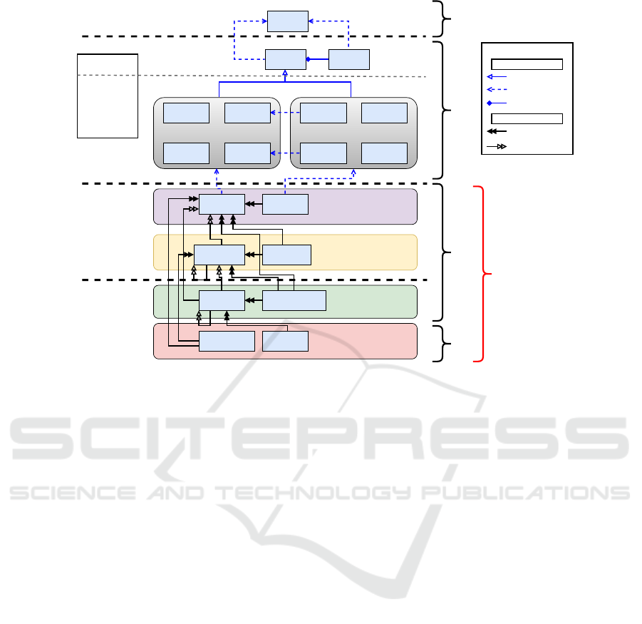
In this paper, an analysis of the OPC UA mod-
elling layers and relevant modelling elements is done
(shown in Fig. 1). The analysis is based on the OPC
UA specifications defined under parts 3 and 5 (OPC
Foundation, 2021) (OPC Foundation, 2020b). While
UML relationships are used to define associations
among various modelling elements belonging to the
meta-meta model and the meta-model layer, OPC UA
relationships are used to define associations among
the modelling elements of the information model and
the data model layer. A comparison between the OPC
UA modelling layers and the meta-modelling frame-
work of the Meta-Object Facility (MOF) is shown
in the diagram where M0 represents real-world ob-
jects, M1 defines the model(s), M2 defines the meta-
model, M3 defines the meta-meta model layer (Bram-
billa et al., 2012). Contrary to the MOF, the Model
(domain model and User-defined type model) layer
of OPC UA (M1 in MOF) contains both types and in-
stances.
3.1 Meta-Meta and Meta Model
OPC UA uses an object model to describe the enti-
ties of the application domain. An object may contain
variables and methods that describe the characteris-
tics and functionalities of that object (OPC Founda-
tion, 2021). Apart from that, relationships are used
to define different types of associations amongst var-
ious objects. However, in the OPC UA server, the
objects as well as their components (e.g. variables
A Modelling Methodology for Developing an Information Model for Cyber-Physical Production Systems using OPC UA
153
Node
ObjectType
VariableTypeReferenceType
DataType Object
Variable
Method
View
Standard
Types
Standard
Instances
Base Information Model
Domain-specific
Types
Domain-specific
Instances
Companion-specification Model
User-defined
Types
Type-model specific
Instances
Type Model
use-case
Instances
Instance Model
application-
domain Instances
Meta-meta model
Address Space
Model
(Meta model)
Information Model
(Domain Model)
Data Model
(User-defined Model)
Types Instances
Legends
OPC UA Server
Address Space
Generalization
HasTypeDefinition
Dependency
HasSubType
UML Relationships
OPC UA Relationships
Attribute
Composition
<<instanceOf>>
M3
M2
M1
M0
Class
<<instanceOf>><<instanceOf>>
Node Model
Figure 1: A separation of layers of the OPC UA modelling paradigm based on the OPC UA specifications.
and methods) and their relationship types are repre-
sented as Nodes. Nodes constitute the fundamental
building blocks of the OPC UA information model.
Each Node contains a set of attributes that define the
characterises (e.g. type, identification) of that partic-
ular node (OPC Foundation, 2021). In Fig. 1, the
“Node Model” is represented as a sub-layer of the
meta-model layer. From the meta-modelling perspec-
tive of object-oriented modelling, both the Node and
Attribute can be classified as classes which are in-
stances of a superclass named “Class” (as shown in
the Meta-meta model layer).
OPC UA standard defines a set of 8 Node classes
which are sub-typed from the base node class (Node).
These node classes can be divided into two sub-
categories depending on their usage purpose. The
types are used to define type information for objects,
variables, literal values, and relationships among ob-
jects. Instance classes represent the instances of the
type classes. While the Object and Variable node
class can be identified as instances as they have an in-
heritance dependency to the ObjectType and Variable-
Type node class, the Method and the View node class
don’t have any type. As these node classes are used to
model the OPC UA server address space (i.e. models
of the underlying system), this layer is also called the
address space model of OPC UA (OPC Foundation,
2021).
3.2 Base Information Model
The information model layer contains a base infor-
mation model (a standard model defined by the OPC
Foundation and acts as the base of the OPC UA server
address space) and companion-specification models
(discussed later). The base information model con-
tains a set of standard type and instance nodes that
the modeller can use to develop custom models (OPC
Foundation, 2020b). In this paper, the base informa-
tion model is divided into multiple sub-models where
each sub-model contains a specific node set catering
to particular functionality or use case. The description
of these sub-models is provided below (OPC Founda-
tion, 2022):
• Core Information Model. It contains all the base
type and their sub-type nodes (e.g. BaseObject-
Type, BaseVariableType) and a set of standard in-
stance nodes (e.g. Root, Server) for organizing
the address space.
• Event Model. Extension of the core object
model. It can be used to model different types
of events in the address space.
• Interface Model. Another extension of the core
object model. It can be used to model additional
features of an ObjectType.
• Capabilities & Diagnostics Model. This node
set is specific to the OPC UA server and describes
the capabilities of the server.
MODELSWARD 2023 - 11th International Conference on Model-Based Software and Systems Engineering
154

• Security Model. Nodes in this sub-model are
used to model the security aspects of the OPC UA
server (e.g. roles and access, security certificate).
• Data Access Model. Extension of the core vari-
able model can be used to model process automa-
tion data (e.g. DataItemType) and their associated
metadata.
• Historical Data Access Model. This node set can
be used to identify nodes whose data values are
historized in the database for post-processing.
• Alarms and Conditions Model. Nodes in this
sub-model can be used to model events and noti-
fications generated by the system.
• State Machine Model. These nodes can be used
to model the behaviour of the applications running
on the system or programs running on the OPC
UA server.
• Publisher-Subscriber Model. These nodes can
be used when the publisher-subscriber (pub-sub)
mechanism of the OPC UA server is enabled. This
sub-model is optional.
• Network Model. The nodes of the base network
model (BNM) are used for defining network-
related elements of a host device running the OPC
UA server.
• Safety Model. This sub-set of nodes can be used
to model safety aspects of the system
• Aggregate Model. These nodes can be used
to model aggregate data and configuration of an
OPC UA server.
This sub-model categorization of the base informa-
tion model, based on different aspects of the system,
could be useful for mapping data to relevant models.
3.3 Domain-Specific Models
Apart from the base information model, various stan-
dardizing body also developed their domain-specific
information models for the OPC UA standard. These
models, also known as companion specifications,
generally extend the types defined in the base in-
formation model and introduce special types rel-
evant to that particular domain. The OPC UA
information model for IEC 61131-3 based PLCs
from the PLCopen organisation is an example of
domain-specific information models (OPC Founda-
tion, 2020a). Apart from that, the OPC Foundation
also provides a few generic domain models (e.g. De-
vice Integration (DI) model for device description, In-
dustrial automation (IA) model) that are intended to
be starting points for companion specifications. Fig.
Base
Object
Type
Base
Variable
Type
Base
Reference
Type
Base
Data
Type
Standard
Instances
Event
Model
Interface
Model
Data
Access
Model
Historical
Data Access
Model
A& C
Model
State-
Machine
Model
Base
Network
Model
Pub-Sub
Model
Security
Model
C&D
Model
Safety
Model
Aggregate
Model
Device
Integration
Model
Industrial
Automation
Model
1
2
3
4
Core Information Model
Sub-models of the base information
model (no separate spec defined)
Sub-models of the base information
model (separate spec defined)
Companion-sepcification defined by
OPC Foundation
Figure 2: Various Sub-models of the base information
model and their extensions.
2 depicts various sub-models described in the previ-
ous sub-section. Sub-models belonging to categories
1, 2, and 3 constitute the base information model. The
generic DI and IA model is also included in the dia-
gram as they extend the base model.
3.4 User Models
The user-defined model (lowest layer in the modelling
paradigm) consists of type models and instance mod-
els that are specific to that particular application do-
main where the OPC UA server is implemented. For
the sake of re-usability, the user model is separated
into two sub-layers. The Type model should contain
custom types that are sub-typed either from the base
types or domain-specific types defined in the compan-
ion specifications. The type model could be an aggre-
gate of multiple type sub-models (e.g. model of indi-
vidual devices). These individual models could either
be provided by the machine builders along with the
devices or developed by the end users. The instance
model will contain the actual instances defining the
entities of the domain. Depending on the type of im-
plementation, there could be more than one instance
model.
4 CHALLENGES IN OPC UA
MODEL DEVELOPMENT
PROCESS
In this section, a list of generic challenges is described
that a modeller could face while developing the OPC
UA information model from domain knowledge.
• Translation of Domain Knowledge (Ch
1
). The
initial step in the model development process
is identifying information requirements for the
model as it serves as the foundation of the model
development (Y. Tina Lee, 1999). This can be
done by analysing the production systems and
A Modelling Methodology for Developing an Information Model for Cyber-Physical Production Systems using OPC UA
155

producing a set of documents/artifacts that could
be used by the modeller. However, translating this
system knowledge directly to OPC UA concepts
could be a challenging task for the modeller. One
of the primary reasons behind this is the absence
of a formal semantic description methodology for
modelling entities in the OT domain. Therefore,
it is up to the modeller to derive the semantics and
map them to OPC UA concepts which could be a
complex time-consuming effort.
• Creating Type Information (Ch
2
). The informa-
tion collected from the system analysis provides
only the instance data without any type informa-
tion. The responsibility to create types from the
instance data falls on the shoulder of the modeller
(i.e. the type model(s)). A type model may con-
tain more than one ObjectTypes, VariableTypes,
ReferenceTypes, and DataTypes which might be
dependent on each other (e.g. An ObjectType
might contain a variable instance which is of a
new VariableType). Understanding the dependen-
cies within the model as well as identifying start-
ing points for types could be a challenging task
for the modeller.
• View Separation Within the OPC UA Model
(Ch
3
). In general, one single model is not enough
to describe every aspect of a system which is why
various modelling standards define different types
of models that depict different aspects of a system.
However, as seen in Fig. 2, the base information
model of OPC UA merges different aspects of the
system into one single model. Therefore bringing
all modelling aspects into a single model could
be challenging as people from different domains
have knowledge of their respective fields (e.g. a
PLC programmer develops a control application
while a network engineer has more knowledge of
the automation networks).
• Access to Model(s) from the Client-Side(Ch
4
).
In order to enable automatic configuration and
data acquisition from the OPC UA server, the
client applications should possess the knowledge
of the OPC UA models inside the server. How-
ever, making every single model available to all
OPC UA clients might not be an efficient solution.
5 METHODOLOGY
Concerning the challenges described in Section 4,
a generic modelling methodology is proposed that
can be used as a guideline for the OPC UA model
development process. The described methodol-
ogy is adopted from existing information modelling
concepts of software engineering. The modelling
methodology is divided into 5 different phases. A
swimlane diagram depicting these 5 phases is pro-
vided in Fig. 3.
1. Investigation. This step involves analysing
the existing system and gathering information
that should be modelled into the OPC UA ad-
dress space. System analysis involves inter-
departmental collaboration as the knowledge re-
garding the system is generally distributed among
the employees belonging to different domains
within the company. Therefore, the goal is to as-
semble information from scattered sources and to
establish a rough overview of the existing system.
Reviewing existing system documentation as well
as having discussions with the employees involved
in the production should also be part of the inves-
tigation process. The OPC UA server will contain
information regarding the existing physical assets
and their respective process behaviour. Therefore,
the infrastructure involving physical assets should
be the primary focus of system analysis and it
should be done in a bottom-up approach. The
gathered system information can be formalized
using either company-specific domain ontologies
or existing standard ontologies. The information
also can be stored in a system knowledge base
for model creation at a later phase. A glossary
of terms should be defined in this phase that will
be used to describe the gathered system data. This
will be helpful in translating the domain knowl-
edge (Ch
1
) as well as generating type information
(Ch
2
). Apart from that, the knowledge base could
be used by the clients to query models (Ch
4
).
2. Conceptualization. As described in Section 3,
the user models consist of the type and instance
models. However, the system information gath-
ered in the first step contains only instance data
without any type of definition. Therefore, in this
phase of model development, the primary focus
should be to identify the type of information of the
entities of the system. In general, the goal of this
phase is to develop a generic technology-agnostic
overview of the system that will act as a common
base for all the stakeholders in the model devel-
opment process (system model(s)). System infor-
mation from the previous step as well as the glos-
sary should be used as building blocks for the sys-
tem model(s). First, a separation of the physical
and cyber entities should be done. Based on the
concept of CPPS, the physical entities would be
the environmental entities like the machines and
their components, and physical interfaces like the
MODELSWARD 2023 - 11th International Conference on Model-Based Software and Systems Engineering
156
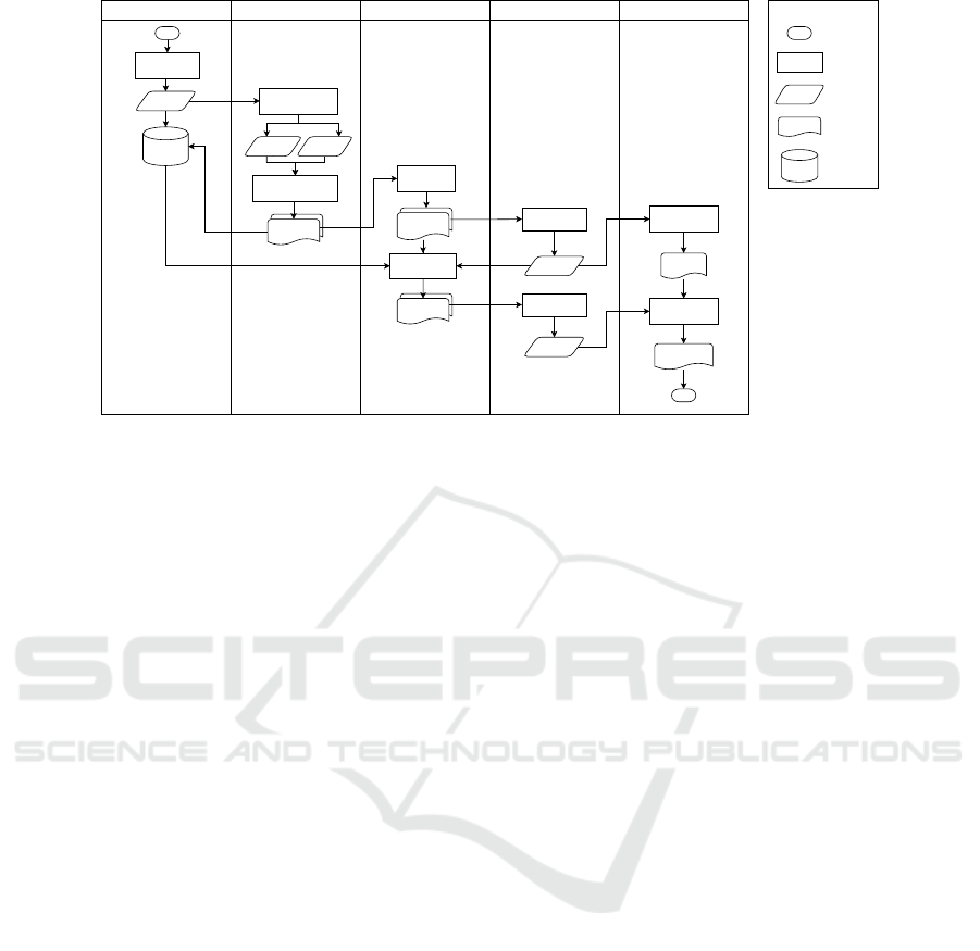
Investigation Conceptualization OPC UA Model Creation Model Validation Code Generation
Start
System analysis
System
Information
Separate physical
and cyber entities
Physical
entities
Cyber
entities
Analyse structural &
behavioral components
Knowledge
Base
Create
type model(s)
Create
instance model(s)
Validate type
model(s)
Address space
generation
Address Space
Type Library
End
Validate instance
model(s)
Confirmation
Type library
generation
System
Model(s)
Type
Model(s)
Instance
Model(s)
Confirmation
Terminator
Process
Data
Artifact
Database
Diagram notations
Figure 3: A swimlane diagram portraying the activities of the OPC UA model development process.
sensors and actuators. Computing resources like
PLCs and industrial computers could also be mod-
elled. Cyber entities are logical software compo-
nents like a control program or a service for con-
figuration and monitoring. The primary goal of
this separation is to create different views of the
system (Ch
3
)
Structural and behavioural analysis of both the
physical and cyber entities is also necessary in or-
der to understand system composition and func-
tionalities. The “System Model(s)” artefacts
(shown in Fig. 3) are generated at the end of
the conceptualization phase and contain the type
information for the system. Thus, these models
can be used to handle the challenge (Ch
2
) men-
tioned in the previous section. As modelling is
an iterative process, a system model in the mid-
dle could be beneficial because instead of updating
the OPC UA information model, only the system
model should be updated in every iteration until
the model is finalised. Apart from that, being a
technology-abstract model, it will provide a gen-
eral understanding of the system to the people not
involved in the modelling process or doesn’t pos-
sess any knowledge regarding the OPC UA mod-
elling techniques. Apart from that, this model
could be used for developing innovative business
use cases and generating system documentation.
It is also possible to generate information models
of other automation standards (e.g. MTConnect)
from these system model(s).
3. OPC UA Model Creation. In this phase, concrete
OPC UA models should be developed from the
system models generated in the previous phases.
The first step is to develop the type of models
(specific to this particular domain) which can be
done either manually or via an automated model
transformation process. However, for both cases,
a mapping between the concepts of the system
model(s) and the OPC UA modelling elements is
necessary. This can be done with the help of a pre-
defined glossary, as mentioned in the first phase.
The type model should be developed first followed
by the instance models. For the type, the first step
should be to create all the custom ObjectTypes. As
OPC UA follows an object model approach, cre-
ating ObjectTypes at the beginning is an obvious
choice for model development strategy. Creating
a custom ObjectType requires identifying starting
point i.e. the super-type from one of the existing
models from which it will be sub-typed.
It might be the case that different ObjectTypes in
the type model are sub-typed from super types be-
longing to different existing models, i.e. some
types are sub-typed from the base information
model while others could be sub-typed from vari-
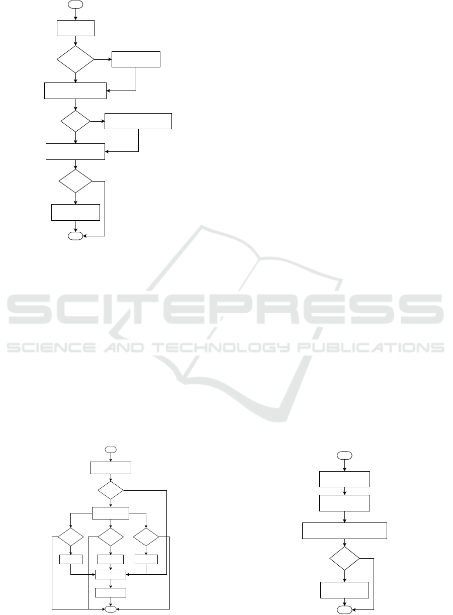
ous companion specifications. A flowchart depict-
ing the ObjectType creation is provided in Fig. 4.
For complex types, component instances under the
type should be created based on the structure of
the complex type (Fig. 5). This component cre-
ation follows the rule of InstanceDeclarations de-
fined under the OPC UA specification (OPC Foun-
dation, 2021). Similar to ObjectType, Variable-
Types, ReferenceTypes, and DataTypes also can be
created following the same process. A flowchart
depicting the creation of a VariableType is pro-
vided in Fig. 6. One important point to consider
before starting the type model development is to
choose a proper namespace for the model. The
A Modelling Methodology for Developing an Information Model for Cyber-Physical Production Systems using OPC UA
157
Identify suitable
comp. spec.
Comp. spec
found?
Identify the parent
ObjectType from comp. spec
Yes
No
Use a generic comp.
spec. as starting point
Parent
exists?
Create new sub-type from
parent ObjectType
Yes
Identify parent ObjectType from
Base Information Model
No
Start
End
No
Create Components
Has comp?
Yes
Figure 4: Flowchart for creating an OPC UA ObjectType.
namespace should be unique for the type model
so that it can be reused for the different appli-
cation domains. Machine builders can choose
their company-specific namespaces while end-
users can create machine-specific namespaces.
The flowcharts could also be used to automate the
model and documentation generation process.
After the generation of type model(s), they should
be validated before creating the instance model(s),
as part of the instance model will be dependent on
the newly developed type model(s). For the in-
stance model creation process, data stored in the
knowledge base should be used as input. For in-
stance model generation, the first step should be
to identify the entry point in the address space for
Compare with Comp(s).
of super-type
Has obj.
comp.?
Create object
instance(s)
Has var.
comp.?
Create
variable(s)
Has
methods?
Create
Method(s)
Configure
Modelling rules
Yes
Yes
Yes
No
No
No
Need new
comp?
separate comp(s) and
Identify relationship(s)
Start
End
Create groups for
organising nodes
No
Yes
Figure 5: Flowchart for creating components of types.
organising the objects. This could be done either
by checking the documentation of the used com-
panion specifications or the standard instances of
the base model. However, if an entry point is de-
fined in the user-defined type model, that should
be given priority over the base models or com-
parison specification. In general, the object in-
stance named “Objects” of FolderType, defined in
the base information model should be used as the
base starting point (OPC Foundation, 2021). In-
stance nodes relevant to physical assets should be
created first (i.e. structural component and be-
havioural components nodes). A physical asset
might contain multiple cyber components (i.e. a
physical device may run several software applica-
tions/services). In that case, the cyber component
nodes should be created under the physical com-
ponent node using proper reference types. How-
ever, these nodes can be grouped separately un-
der different FolderType objects for organisational
purposes using non-hierarchical references.
In general, instantiating a complex type should
create all the child nodes under the parent instance
node. However, one parent node might contain
child nodes from other types which would not
be instantiated automatically and should be added
separately using proper ReferenceTypes. Apart
from that, the instance models might also contain
additional nodes based on developed use cases.
For example, a set of nodes could be used to
show a set of calculated values from the process
data. While type models can be identified using
unique namespaces, instance models are specific
to OPC UA servers (in general namespaceindex
is reserved for server namespace URI). Therefore,
it could be a best practice for the application de-
velopers to use specific namespaces for instance
models and specific identifier generation mecha-
nisms for nodes in the instance model. As shown
Create sub-type from
the parent type
Configure data type of the value
attribute, ValueRank &
ArrayDimensions
Start
End
No
Create Components
Has comp?
Yes
Identify starting point
for sub-typing
Figure 6: Flowchart for creating an OPC UA VariableType.
MODELSWARD 2023 - 11th International Conference on Model-Based Software and Systems Engineering
158

in Fig. 3, the artefacts generated in this phase are
the OPC UA type and instance models that could
be used directly for code generation.
4. Model Validation. The processes in this phase
should be executed in parallel with the previous
model creation phase. This phase involves vali-
dating the developed type model(s) first and then
validating the instance model(s). Model validation
includes a check for semantic as well as syntactic
validation based on the OPC UA specification. An
example of semantic validation could be check-
ing if all the variables and methods in the address
space are part of either an ObjectType, Object, or
VariableType. Syntactic validation will check if
the serialized model follows the notations defined
by the OPC UA standard (e.g. nodeset schema
from the OPC Foundation).
5. Code Generation. In the last phase of the model
development process, code can be generated di-
rectly from the developed type and instance mod-
els using certain code generation tools. The type
libraries could be generated first from the type
models which can be reused in different applica-
tions. The OPC UA server address space code is
specific to the application domain and can be inte-
grated directly into the OPC UA application. The
code generation process will depend on the choice
of the programming language of the end-user.
6 CONCLUSION & FUTURE
WORK
To summarize, this position paper provides a de-
tailed analysis of the OPC UA information mod-
elling paradigm and based on the analysis, a generic
model development methodology is provided along
with detailed descriptions of individual steps. For the
OPC UA model creation process, flowcharts are pro-
vided as guidelines for creating custom types and in-
stances. The methodology is generic and therefore
applicable to any existing model development tech-
niques. In the methodology, the development of a set
of technology-agnostic intermediary system model(s)
to describe the different characteristics of the system
is proposed. These system model(s) could be compa-
rable to the PIMs from the MDA concept or domain
models of domain-driven design. Future work in this
direction would be to investigate and develop mech-
anisms to generate the structural and behavioural as-
pects of system model(s). Apart from that, a survey
of suitable modelling languages for the implementa-
tion of system model(s) is also necessary. Apart from
that, a mapping of concepts from the generic system
model(s) to the OPC UA model is necessary for the
auto-generation of address space. To achieve that, a
meta-model for the CPPS domain should be devel-
oped first. This could be a topic for research as cur-
rently there exists no abstract meta-model for mod-
elling entities in CPPS. Regarding system analysis
and knowledge translation, a framework can be de-
veloped which can automate the analysis and model
generation process. The architecture, as well as the
functionality of this framework, could also be consid-
ered as a future work of this paper.
REFERENCES
Brambilla, M., Cabot, J., and Wimmer, M. (2012). Model-
Driven Software Engineering in Practice. Morgan &
Claypool Publishers.
Buchgeher, G., Dorninger, B., Klammer, C., Walchshofer,
A., and Kern, A. (2022). Migrating cyber-physical
systems to opc ua. Procedia Computer Science,
200:276–283.
Lee, B., Kim, D.-K., Yang, H., and Oh, S. (2017). Model
transformation between opc ua and uml. Computer
Standards & Interfaces, 50:236–250.
Mahnke, W., Leitner, S.-H., and Damm, M. (2009). OPC
Unified Architecture. Springer, first edition edition.
OPC Foundation (2020a). OPC UA For Programmable
Logic Controllers Based On IEC 61131-3.
OPC Foundation (2020b). OPC Unified Architecture Part
5: Information Model.
OPC Foundation (2021). OPC Unified Architecture Part 3:
Address Space Model.
OPC Foundation (2022). OPC Unified Architecture Part 1:
Overview And Concepts.
Pauker, F., Fr
¨
uhwirth, T., Kittl, B., and Kastner, W. (2016).
A systematic approach to opc ua information model
design. Procedia CIRP, 57:321–326.
Pauker, F., Wolny, S., Fallah, S. M., and Wimmer, M.
(2018). Uml2opc-uatransforming uml class diagrams
to opc ua information models. Procedia CIRP,
67:128–133.
Rohjans, S., Piech, K., and Lehnhoff, S. (2013). Uml-based
modeling of opc ua address spaces for power systems.
In 2013 IEEE International Workshop on Inteligent
Energy Systems (IWIES), pages 209–214. IEEE.
Schmied, S., Mathias, S. G., Großmann, D., M
¨
uller, R. K.,
and Jumar, U. (2021). Information modelling with fo-
cus on existing manufacturing systems. Annual Re-
views in Control, 51:392–400.
Toutenburg, H. and Kn
¨
ofel, P. (2008). Six Sigma: Methoden
und Statistik f
¨
ur die Praxis. Springer-Verlag.
Vogel-Heuser, B., Kegel, G., and Wucherer, K. (2009).
Global information architecture for industrial automa-
tion. atp edition, 51(01-02).
Y. Tina Lee (1999). Information modeling: From design to
implementation. In Proceedings of the second world
manufacturing congress.
A Modelling Methodology for Developing an Information Model for Cyber-Physical Production Systems using OPC UA
159
