
Visualizing Errors and Inconsistencies in the DSML IEC 61499
Michael Oberlehner
1
, Bianca Wiesmayr
1
,Hafiyyan Sayyid Fadhlillah
2
and Alois Zoitl
1,2
1
LIT CPS Lab, Johannes Kepler University Linz, Austria
2
CDL VaSiCS, Johannes Kepler University Linz, Austria
{michael.oberlehner, bianca.wiesmayr, hafiyyan.fadhlillah, alois.zoitl}@jku.at
Keywords:
Visual Programming, Error Visualization, Modeling Tool Usability, Model-Driven Software Engineering,
Cyber-Physical Production Systems.
Abstract:
Errors of textual programming languages are usually detected by the compiler. These errors are then visu-
alized by the IDE and made available to the developer. This paper is intended to show a novel approach to
also propagate errors in visual programming languages to the developer. We analyzed the visual block-based
language of IEC 61499 and implemented an error visualization mechanism in the Eclipse-based IDE 4diac.
As IEC 61499 is a Domain-Specific Modeling Language (DSML) that includes a type system, we also im-
plemented a mechanism for detecting inconsistencies. With this approach, it is possible to work on broken
applications, giving developers the opportunity to fix them in a graphical editor. Furthermore, inconsistencies
that lead to errors are now displayed rather than being hidden from the developer and hard to detect.
1 INTRODUCTION
Efficient modeling tools are essential for the adop-
tion of model-driven software engineering. These
tools need to support engineers throughout the pro-
cess, which includes handling erroneous models. Er-
rors are a normal part of the editing process although
generally undesired: During most of the develop-
ment, modeled applications are incomplete. Further-
more, updating one part of the software frequently
requires editing related parts as well. Avoiding er-
rors altogether may negatively affect the usability
of a modeling tool, as it increases the resistance to
change (Blackwell and Green, 2003). Especially
when developers need to interrupt their work, they
benefit from fault-tolerant tools that allow saving and
restoring erroneous models. In addition, errors can be
introduced during versioning (Demuth et al., 2015) if
merge conflicts occur or incorrect merges are made.
Minor differences between tool environments can fur-
thermore cause errors when a project is ported be-
tween vendors. If an erroneous project cannot be
viewed in a graphical editor, manual fixes in the tex-
tual representation of the model are required to restore
the project. Hence, even IDEs that focus on avoiding
errors during development altogether need to grace-
fully handle erroneous projects.
IEC 61499
1
is an industrial standard that defines a
domain-specific modelling language (DSML), which
enables modeling software for cyber-physical produc-
tion systems (Zoitl and Vyatkin, 2009). The standard
targets automation engineers who are used to develop
such software in a visual manner by defining graphi-
cal diagrams like a block-based application diagram.
IEC 61499 defines language elements such as Func-
tion Blocks (FBs) and connections for implementing
software in production automation systems. Defining
own FB types allows their repeated use in applica-
tions. They are stored in a type library together with a
set of elementary blocks. IEC 61499 is a visual mod-
eling language. A language can be classified as a vi-
sual language if the elements of the model are rep-
resented as nodes, wires, and containers (Sui et al.,
2008). The FBs of IEC 61499 are nodes; connec-
tions are wires; and applications or sub-applications
act as containers. Whereas in classical programming
the developer focuses directly on the textual represen-
tation of the source code file, the visual programmer
focuses on the graphical representation of the source
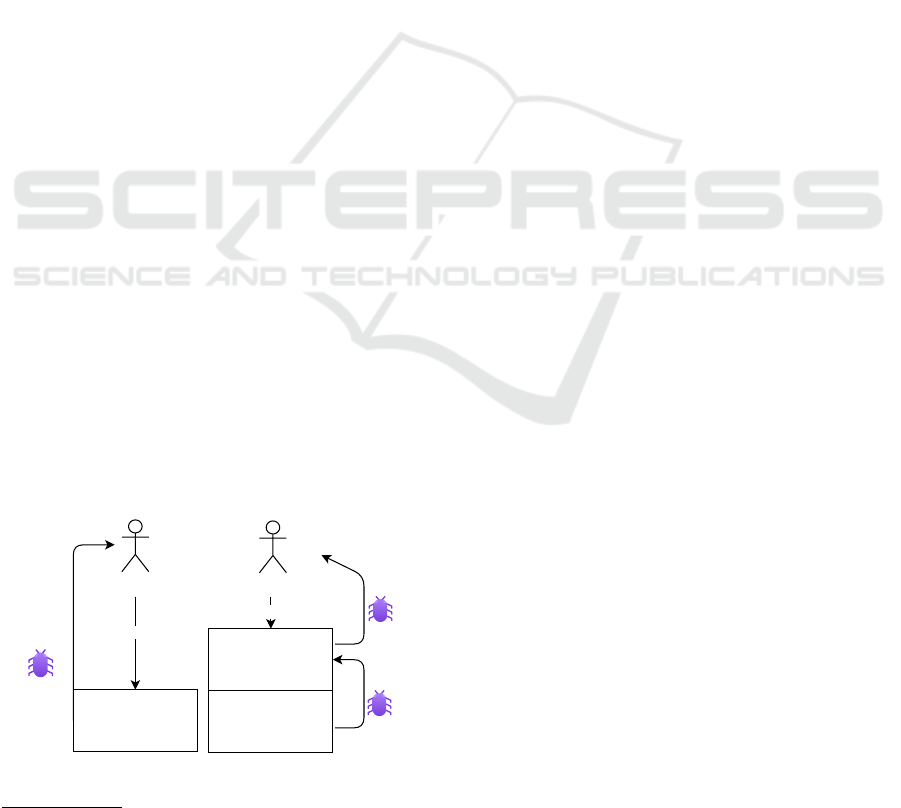
code (cf., Figure 1). Visual programming languages
thus have an additional layer of abstraction compared
to textual ones. As illustrated, the visual developer
has to validate two layers of source code representa-
tions. Hence, errors need to be propagated from the
textual source code to the visual representation to be
accessible to visual programmers. A recent usability
1
IEC 61499-1 Function blocks – Part 1: Architecture
Oberlehner, M., Wiesmayr, B., Fadhlillah, H. and Zoitl, A.
Visualizing Errors and Inconsistencies in the DSML IEC 61499.
DOI: 10.5220/0011683800003402
In Proceedings of the 11th International Conference on Model-Based Software and Systems Engineering (MODELSWARD 2023), pages 143-151
ISBN: 978-989-758-633-0; ISSN: 2184-4348
Copyright
c
2023 by SCITEPRESS – Science and Technology Publications, Lda. Under CC license (CC BY-NC-ND 4.0)
143
study for Eclipse 4diac IDE
2
also identified a clear
need for handling errors gracefully (Wiesmayr et al.,
2021).
Our current work evaluates how error detection
and handling can be integrated in visual programming
languages and their IDEs. In particular, we discuss
the integration based on the DSML IEC 61499. As the
open-source modeling tool 4diac IDE was built us-
ing common Eclipse technologies, such as the Eclipse
Modeling Framework (EMF) and the Graphical Edit-
ing Framework (GEF), parts of our results can be gen-
eralized. We focus on visualizing errors and prevent-
ing a potential information loss as well as visualizing
and preventing hidden inconsistencies. Another goal
of this work is to not alter the language specification,
hence, the proposed error visualization does not influ-
ence the persistent state of the model.
2 RELATED WORK
The problem of communicating errors to developers
is not limited to visual languages. Especially novice
developers have difficulties in understanding and re-
solving compile errors in textual programming lan-
guages (Prather et al., 2017). User studies help in-
vestigating the effect of error presentation. For in-
stance, (Denny et al., 2020) replaced traditional com-
piler error messages with more readable messages
that contain resolution hints. These improved mes-
sages significantly reduced the debugging time of an
application. Some IDEs follow a strategy of avoiding
errors by offering complex editing operations. Fol-
lowing the usability notation from (Blackwell and
Green, 2003), avoiding errors particularly affects the
cognitive dimensions enforced lookahead and prema-
ture commitment because the fixes for all subsequent
changes need to be known in advance. When resolv-
ing errors, the usability of the tool support heavily in-
fluences the success of developer in resolving errors.
Source code file
Source code file
focus
Visual representation
of source code
focus
Error
propagation
over one
layer
Error
propagation
over two
layers
Visual developer
Visual developer
Figure 1: Comparing the focus of a textual developer to the
one of a visual developer.
2
Eclipse 4diac - https://www.eclipse.org/4diac/
This even applies to cosmetic details, i.e., how the
error is presented in the tool (Dong and Khandwala,
2019). The work of (Dillon and Thompson, 2016)
outlines that poor tool usability can even affect the
code quality when users tend to refactor code man-
ually rather than relying on the functionality of their
IDE. Refactoring operations in IDEs can avoid errors
by performing composite actions such as automated
renaming. (Marchezan et al., 2022) described how
to assist developers in repairing inconsistent models.
Their strategy is to build a tree with a subset of repair
actions focusing on the root cause of the inconsisten-
cies and to provide relevant repair actions to the devel-
oper. The work of (Khelladi et al., 2019) investigated
whether repairing an inconsistent model has positive
or negative side effects. A positive side effect means
that the repairing operation also solves other incon-
sistency unintentionally. In contrast, a negative side
effect produces new inconsistencies after the repair
action has been performed. The work of (Ohrndorf
et al., 2018) described and validated model consis-
tency rules. They use the model history to repair the
model. Their approach assumes that a model history
is available, which not always the case in the domain
of automation engineering.
3 SCENARIO ANALYSIS
This section shows common errors or inconsistencies
that engineers are facing in the daily development
process with block-based languages. This scenario
analysis applies to all block-based languages that al-
low multiple connections from one block to another
via multiple pins. Another requirement is the possi-
bility to define block types that can change their inter-
face. The modeling language of IEC 61499 has been
chosen as a showcase because the modeling language
is executable and the concepts can be applied to sim-
ilar DSMLs with node-linked diagrams. Section 3.1
will provide the background to understand the scenar-
ios described in Sections 3.2 to 3.5.
3.1 Modeling Applications in IEC 61499
In IEC 61499, the software of a cyber-physical pro-
duction automation system is modeled as a network
of connected FBs that can be distributed among sev-
eral connected resources. Every FB has to be im-
plemented as an FB type which defines its inter-
face and behavior. An FB type can be compared
to a class definition in object-oriented programming
(OOP), whereas an FB instance can be seen as an in-
stantiated object of a class. The interface of a block
MODELSWARD 2023 - 11th International Conference on Model-Based Software and Systems Engineering
144
is defined as a set of connection endpoints inside the
block. Every connectable node is called a pin in this
paper. A pin has several characteristics in IEC 61499:
It can be either a data, an adapter, or an event pin. It is
furthermore either an input or an output pin, and the
pin has a name. Data pins have one additional prop-
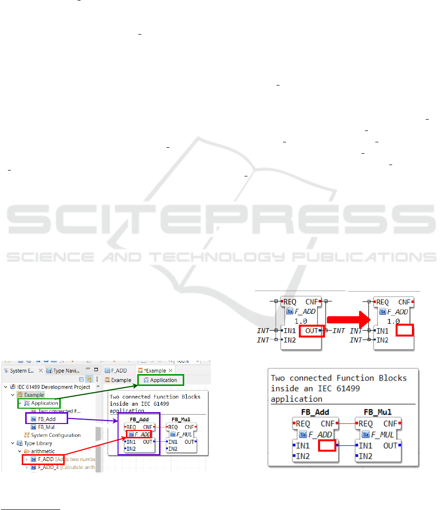
erty, namely a data type. In the example of Figure 2,
the FB instance FB Add has an output data pin OUT
of type INT that can hold one or more connections to
other blocks. This block is part of an application and
it is an instance of the block type F ADD. The behav-
ior of the block type needs to be defined as a textual
algorithm. The FB types are persisted as a collec-
tion of XML files in the type library. The file format
is defined in the IEC 61499-2
3
standard and must be
followed by every IEC 61499 IDE. Figure 2 shows
the elements of an IEC 61499 development project,
i.e., one or more applications and a type library. Sys-
tem configuration files or other IDE-related artifacts
are out of the scope of this paper. As shown in the
example of Figure 2, the FB instance FB Add inside
the application is represented as a block type, namely
F ADD. This type is persisted in the type library as
an XML file. After a new type has been implemented,
it can be instantiated inside the application. Besides
building applications out of instances, the developers
can also model new types and attach them to the type
library. Newly constructed types can themselves use
instances of existing FB types, since IEC 61499 al-
lows constructing the composition types subapplica-
tion (SubApp) and Composite Function Block (CFB).
As long as the types within the library are not edited,
the application and the type definitions will remain
stable. After a type change, it is not guaranteed that
the application is still valid. Possibly, the FB in-
stances need to be adapted as well. When exchang-
ing or updating FB types in the library, the developer
needs to verify all applications which are holding an
instance of the changed type. Research by (Sonnlei-
BLOCK TYPE
BLOCK INSTANCE
Figure 2: IEC 61499 development project in Eclipse 4diac
IDE with type library (left) and application (right).
3
IEC 61499-2 Function blocks – Part 2: Software tool
requirements
thner et al., 2022) has shown that IEC 61499 applica-
tions can have more than 8000 nodes and 45000 con-
nections. Therefore, verifying applications manually
requires an enormous effort.
3.2 Scenario 1: Editing the Interface of
a Block Type
Developers may need to edit the interface of an FB
type to address changing requirements. If instances of
the edited block type are contained in the application,
it is not guaranteed that the whole application is in a
consistent state after the change. We demonstrate this
based on the scenario of deleting the pin OUT from
the type F Add (cf., (1) in Figure 3). This can af-
fect the application when the respective instances are
connected. When applying this scenario to the exam-
ple in Figure 2, the interface of the instance FB Add
will change as its block type is F Add. Furthermore,
the block FB Add is connected to FB Mul. As deleting
the pin alters the interface of FB Add’s type, the con-
nection inside the application from FB Add.OUT to
FB Mul.IN is also affected by this change. Hence, the
modeled application is in an inconsistent state. Part
(2) of Figure 3 shows that it is unclear what should
happen with the erroneous connection. To address
this inconsistency, the application or the type needs
to be adapted. It has to be ensured that every instance
in the application references the new type, rather than
the changed one. In contrast to deleting a pin, adding
a pin to a type does not influence the application.
Delete Pin OUT
?
(1) Change the interface of block type F_ADD
(2) How to apply that change to the application?
Figure 3: Changing the interface of an IEC 61499 FB type.
Visualizing Errors and Inconsistencies in the DSML IEC 61499
145

3.3 Scenario 2: Editing the Properties
of an Interface Pin
Besides FB types, IEC 61499 also defines data types.
For creating connections between interface pins, the
data types of the connection endpoints have to be
assignable, as IEC 61499 is a strongly typed lan-
guage. In Figure 2, the pins from FB Add.OUT and
FB Mul.IN are of data type INT. As the data types
match, it is allowed to connect the two blocks. Subse-
quently, FB Add could be edited by adapting the data
type of interface pin FB Add.OUT to BOOL. This
change results in a data type mismatch of the connec-
tion endpoints and the application has an erroneous
connection. Whereas Section 3.2 described an incon-
sistency, this scenario reflects a syntax error of the
modeled application. A related scenario is to change
the pin’s identifier. Renaming a pin will not violate
any data type rules, but will raise an inconsistency in
the connection endpoint identifiers.
3.4 Scenario 3: Deleting a Block Type
A missing type constitutes the third scenario that
might be troubling during the development of
IEC 61499 applications. Such an issue can occur in
several situations. The simplest case happens if an
IEC 61499 application is developed and the type of
an FB instance has been deleted from the file system.
Regarding the example in Figure 2, we assume that
the type F Add has been deleted from the type library.
It is then unavailable for the application that currently
holds an instance of F Add, which is therefore built
with no longer existing types. Renaming a block type
file outside the IDE may cause the same problem as
deleting a file.
3.5 Scenario 4: Porting and Versioning
Applications
Large software systems engineering and mainte-
nance is a naturally collaborative process including
a variety of distributed engineering teams, heteroge-
neous development artifacts, and various engineering
tools (Demuth et al., 2015). To enable distributed
work in a multi-user environment, it is essential to
support Version Control Systems (VCSs) such as Git.
When exchanging applications through a Git repos-
itory, merge conflicts and resulting model inconsis-
tencies may occur. Too many inconsistencies in a
persisted modeled application can result in failure to
load the model into the IDE. If the model cannot be
loaded, visual developers cannot resolve the conflicts
since they are not visualized inside a graphical mod-
eling framework. XML files with multiple thousands
block instances often have more than one million lines
of code. This large amount can overwhelm visual de-
velopers. They have difficulties navigating such large
XML files and fixing the errors and inconsistencies
without adding new ones. It is more difficult to find
and track errors in an error-prone XML file compared
to the visual notation. Resolving the conflicts in the
persisted textual form is often not feasible due to the
high complexity. Some graphical editors within IDEs
(e.g., 4diac IDE) are capable of dealing with huge ap-
plications, as they implement sophisticated lazy load-
ing and buffering mechanisms. On the other hand,
the model may be loaded by the IDE, but the incon-
sistency is not visible and therefore not recognized by
the developer. This can hide errors or inconsistencies
until later in the deployment process of a control ap-
plication or, even worse, the error is detected during
operation of a production plant.
4 ERROR AND INCONSISTENCY
DETECTION
Detecting errors and inconsistencies is required in two
different stages. Firstly, validation is required dur-
ing the loading phase when the model instance is cre-
ated. Additionally, the modeled application needs to
be checked continuously while it is edited. Therefore,
during the development process, the IEC 61499 appli-
cation needs to be checked for connection constraints
and inconsistencies. Violated connection constraints
will produce an error, whereas a violated consistency
rule will raise an inconsistency.
4.1 Error Checking
When a block instance should be connected with an-
other one, it has to be checked whether the connec-
tion is allowed. Figure 4 shows a simple example of a
typical check which is executed during the construc-
tion of an IEC 61499 application. The constraints for
connecting two elements are typically rules which are
defined in the standard and have to be checked by the
IDE. However, since it is also possible to edit applica-
tions outside the IDE, this work will make it possible
to work with errors to a certain extent.
4.2 Consistency Checking
The synchronization status between type library and
application needs to be verified because the model-
ing language of IEC 61499 has a type system. This
MODELSWARD 2023 - 11th International Conference on Model-Based Software and Systems Engineering
146
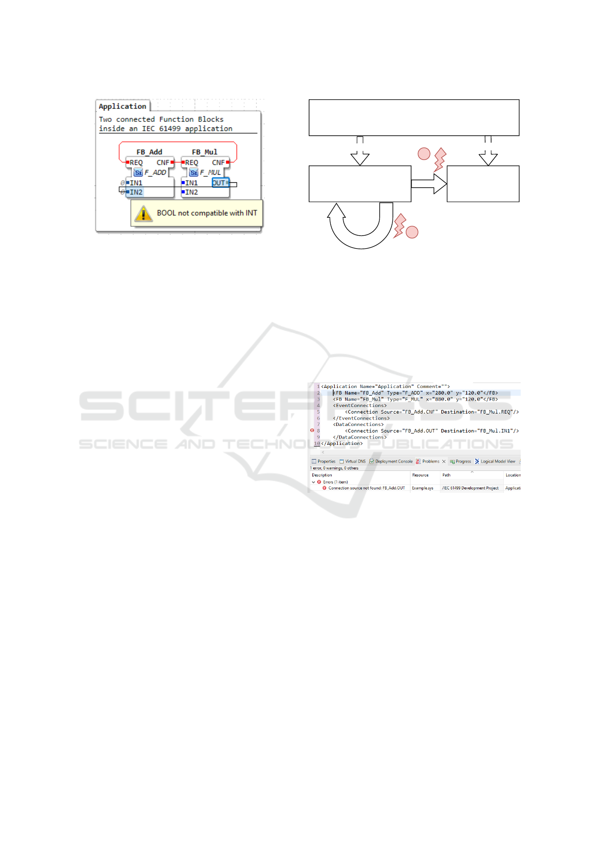
Figure 4: Simple data type check for connecting two blocks.
means that the application needs to verify whether all
used block types are currently available and whether
the block’s interfaces are still valid. The modeling
language of IEC 61499 is defined verbally in the stan-
dard. It has specific characteristics to allow modeling
reusable, custom block types that are later combined
into applications. To achieve this goal, the IEC 61499
provides meta models for modeling reusable types
and applications, which are displayed in Figure 5.
Some modeling elements, such as interface pins, con-
nections, or data types, are applicable for application
and type modeling. Type definitions are required for
modeling applications, as they are composed of in-
stances of these types. Whereas types can be modeled
without other types, it is not possible to model a non-
empty application without types. Therefore, the ap-
plication requires the type library to be implemented.
Since the type library changes whenever a block type
is adapted, we need to perform consistency checks at
two locations, namely between the type library and
the application (marked as (1) in Figure 5); and within
the type library itself (marked as (2) in Figure 5).
Consistency check (2) means that whenever a model
instance changes, equality between the type library
and the initial meta model of an instance needs to be
checked. If a type definition has been changed, we
need to further examine whether this change is rele-
vant to the current application or type instance.
4.3 On-Load Detection
As a first step, the IDE needs to load all types of the
type library, each of them represented as an XML file.
After loading the types, the application model is built
according to the information in the XML-file describ-
ing a system. Since the application uses FB types
from the type library, the respective types have to be
available during construction of the application. The
syntactic correctness of an application can be easily
checked for every element during construction, since
IEC 61499
defines
Type Library Application
defines
consistency
check
consistency
check
1
2
Figure 5: Consistency check between IEC 61499 applica-
tion and type system.
the type library will typically not change during the
loading phase. In textual programming languages, the
compiler commonly adds an error marker to the line
where the error happens. In Figure 6, the scenario
of a deleted pin (Figure 3) is shown in line 14 with
an appropriate error message and label. Since this
work focuses on visual developers, the error needs to
be propagated to the visual layer.
Figure 6: Textual representation of an IEC 61499 applica-
tion via an XML format.
4.4 On-the-Fly Detection
Incremental compilation is required for checking the
source code of a program inside the IDE during de-
velopment. This means that only the currently ap-
plied changes need to be checked by the IDE. In case
of the modeling language IEC 61499, an incremental
change means that the application was adapted (e.g.,
connecting two FBs with a connection). The user
does not need to save the file before an error checking
can happen. On-the-fly detection should avoid errors
as much as possible, but nevertheless, there are a lot of
situations where the user has the possibility to inject
errors into applications. To define which editing oper-
ations may cause an inconsistency or error that affects
the execution of a model, we define the following trig-
Visualizing Errors and Inconsistencies in the DSML IEC 61499
147
ger condition for detecting an inconsistency or error.
They apply to any block instance that is affected by a
change, i.e., an instance that is used in an application
or in another block type: (1) Renaming or deleting
block type; (2) Renaming or deleting an interface pin
of a block type; and (3) Changing the data type of
an interface pin within a block type. Trigger 2 and
3 have the precondition that the corresponding pin is
connected to another block inside an application.
5 VISUALIZING AND
RESOLVING ERRORS
To visualize the errors inside the graphical editor, the
IDE needs to extend the meta model of IEC 61499
with dedicated modeling elements that are capable of
visualizing the errors and inconsistencies. Therefore,
an ErrorMarkerBlock and ErrorMarkerPin have
been introduced. As a further requirement, these addi-
tional elements must not violate the portability of the
modeled control software. Hence, the error elements
need to be created on demand and should not be per-
sisted since errors should be detected also within ap-
plications that were created by other IDEs. The error
marker elements are responsible for caching as much
data as possible from the elements in memory to help
the user resolving the conflict. Introducing graphical
error elements significantly improves the handling for
error-prone applications inside graphical editors.
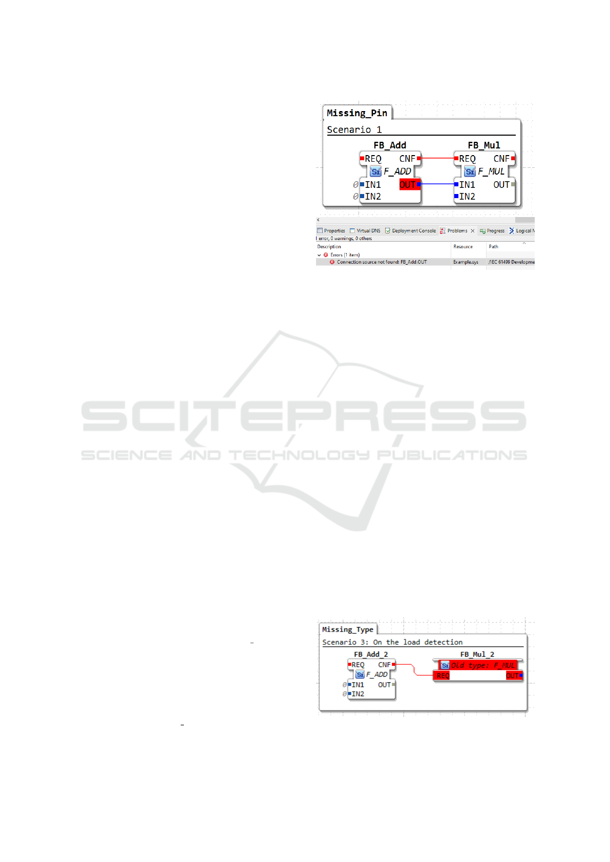
5.1 Visualization of Missing Pin
Figure 7 shows the graphical representation of edit-
ing an interface pin (Section 3.2). The IDE creates
a dummy interface element, which has a red back-
ground indicating an error. To provide further infor-
mation, the error is displayed in the problems view.
The ErrorMarkerPin can hold a connection which
could otherwise not have been created.
5.1.1 Resolving a Missing Pin
Restoring for on-load detection is possible by using
the pin of the connection partner. In the example,
this would be the data type of the pin FB
Mul.IN1.
This data type is buffered in the ErrorMarkerPin,
so that a repair action can be performed even if the
connection partner is lost. On the other hand, restor-
ing for on-the-fly detection is also possible since the
old block type is still buffered in the memory of the
IDE. To resolve the conflict, it is possible to either
adapt the block type FB Add, delete the block, or
adjust the connection. All resolving actions will re-
Figure 7: Inconsistent block type inside an IEC 61499 ap-
plication.
sult in an automatic removal of the ErrorMarkerPin
and the corresponding error message from the prob-
lems view. To perform automatic conflict resolution,
the following steps are needed: First, the pins need to
be added to the block type with their corresponding
name. Afterwards, the IDE needs to search all in-
stances of affected types and replace these instances
with instances of the new type. This means that the
block needs to be replaced and connections have to be
reconnected. Another way of automatic conflict res-
olution is to delete all connections that are associated
with the corresponding pin.
5.2 Visualization of a Missing Type
To visualize a missing type as described in Sce-
nario 2: Deleting a Block type inside an IEC 61499
application, a graphical ErrorMarkerBlock is re-
quired. Figure 8 shows the appearance of an
ErrorMarkerBlock, which has been created during
parsing the persisted version of an IEC 61499 appli-
cation. By looking at the textual representation (Fig-
ure 6) of the application, it can be seen in line 3 that
the type of the FB instance is stored as an XML at-
tribute. Furthermore, the connection attributes (line
8, Figure 6) are providing information about the miss-
Figure 8: Visualization of a block type that has been deleted
before the application was loaded.
MODELSWARD 2023 - 11th International Conference on Model-Based Software and Systems Engineering
148
ing type. Hence, in the example it is possible to de-
rive the following information: type name, pin name,
and type of pin (input or output). For the derived er-
ror block type, a separate entry inside the type library
is created. This entry can now collect information if
suitable interface information is to be collected during
construction of the application. By analyzing the con-
nection opposite pins, it is also possible to derive the
data type of a pin to a certain degree. The restrictions
for deriving the data type pins are the implicit cast-
ing rules of IEC 61499. A small integer data type on
the opposite could also be a big real data type on the
origin and vice-versa. By using the larger data type,
at least a broken connection can be avoided. Further-
more, all collected error-prone connections that refer
to the missing type can extend the interface of the
ErrorMarkerBlock and its error type. Although the
error type is useful for providing resolution helpers to
the application developer, it should not be possible to
instantiate it. Therefore, it is realized as a hidden en-
try inside the type library and it has to be deleted from
the type library after the error has been resolved.
Figure 9: Visualization after a type has been deleted during
development.
Figure 9 shows an error marker block that has
been created during the development process. It can
be seen that no information is lost, since we have the
interface with all pins kept in the memory. During on-
the-fly detection, the IDE recognizes that a type has
been deleted and therefore replaces the block with an
error marker block.
5.2.1 Resolving a Missing Type
For restoring the type, the error marker block stores
the old type in the memory. In contrast to on-load-
detection, by using on-the-fly detection, the error
marker block is capable of restoring the whole inter-
face of the block type since the instance is holding
a copy of the type. To resolve the conflict of all in-
stances automatically, the IDE needs to make the error
type valid. This means, that a file needs to be created
out of the error type and the error type needs to be
moved from the error list to a valid list.
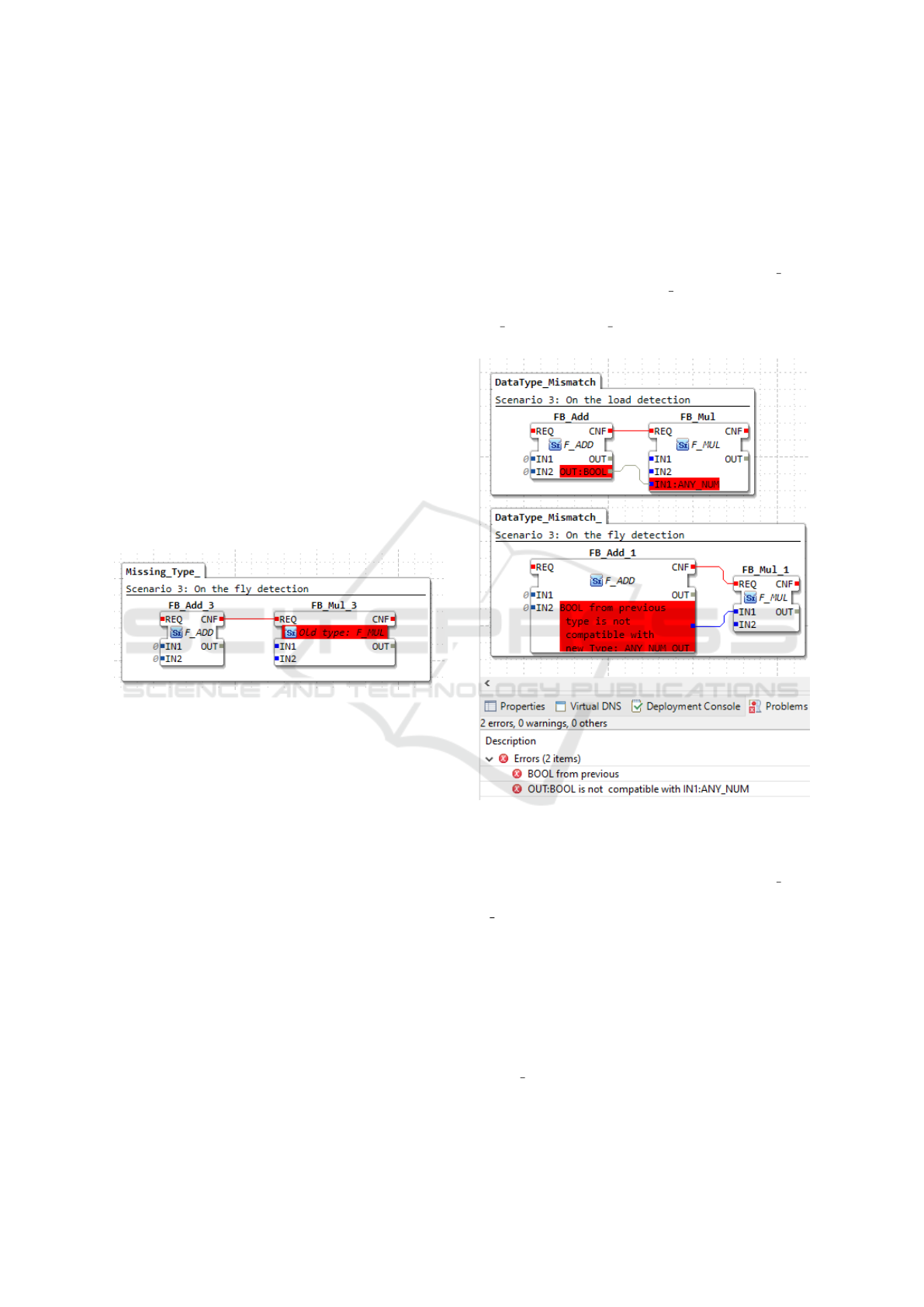
5.3 Visualization of a Data Type
Mismatch
Figure 10 shows the difference of a violated con-
nection constraint between on-the-fly and on-load
detection. The affected change was that the data
type of the pin OUT from the block type F Add
had been changed from ANY NUM to BOOL. Be-
cause of this data type mismatch, the connection from
FB Add.OUT to F Mul.IN is not valid anymore.
On-load detection needs to create two error pins, be-
Figure 10: Visualization of a deleted type that has been
deleted before the application was constructed.
cause the IDE does not know which pin has caused the
fault during parsing. Possibly, the block type F Add
has changed the data type of the pin OUT or the type
F Mul has changed its data type from the pin IN1.
In contrast, for on-the-fly-detection, it is clear which
type causes the fault, as can be seen in the respec-
tive example from Figure 10. Therefore, for on-load-
detection, every pin of the connection needs to have
an error pin. For on-the-fly-detection, the connection
only has one error pin. If this change happens during
development, the IDE can recognize that change and
put an error marker pin to all instances of the block
type F Add.
Visualizing Errors and Inconsistencies in the DSML IEC 61499
149

5.3.1 Resolving a Data Type Mismatch
To resolve the conflict, the connection simply has to
be reconnected onto an interface pin of another block.
Another way of resolving such an error is that the con-
nected block updates its data type in the pin IN1 to
match the connection again. Also, deleting the con-
nection will resolve the conflict. For automatic reso-
lution of conflicts, the IDE needs to apply the changes
to all affected instances. Since the effects of an auto-
matic resolution are difficult to comprehend for devel-
opers, we implemented a user-guided semi-automatic
resolution. First, the user resolves the conflict in the
type, afterwards the user triggers an “update type of
all instances”. For resolving the application, the de-
veloper just has to drag the connection to a pin with
a valid datatype. This will automatically resolve the
error pin. Consider the example in Figure 10. To re-
solve the error with on-the-load detection, the connec-
tion of F Add.Out can be dragged to a pin of datatype
BOOL from any other block. This will result in re-
connecting the connection to F Add.OUT and delet-
ing both error pins.
6 EVALUATION
With the following evaluation, we want to demon-
strate the possibility of loading and resolving incon-
sistent IEC 61499 applications. We picked four differ-
ent IEC 61499 development projects from our indus-
try partner in several versions as evaluation objects.
The projects have been developed in various IDEs and
have been prepared to be imported in Eclipse 4diac
IDE. All projects are representing the executable
software of production automation systems. Before
implementing our error visualization concept, some
projects could not be displayed in a graphical editor
due to errors and inconsistencies caused externally.
The goal of the evaluation was to show that the error
detection and visualization is capable of opening large
error prone applications. Furthermore, an overview of
the amount and category of the error should be pro-
vided to the developer of the automation system. A
resolution of the errors should be possible in a graph-
ical way. Our industry partner used this visualization
to be capable to import the erroneous projects and re-
solve the errors. Table 1 shows some characteristics
of the applications and the counted number of errors
and inconsistencies. The column Missing Type repre-
sents the inconsistency from a type library described
in Scenario 2: Deleting a Block Type. The col-
umn Missing Pin shows an inconsistency discussed
in Scenario 1: Editing an interface. An invalid con-
nection from Scenario 3 is represented in the column
data type mismatch. This column represents the er-
ror of a data type mismatch between two connection
endpoints. As a result of this analysis, it has been dis-
covered that the error column Missing Pin increased
significantly when there are missing types. By taking
application 2 as an example, we concluded that out of
the 907 missing pins, 561 have been created because
the type was missing and therefore also the connec-
tion attempted to connect to an invalid instance. In
application 2, the major problem was a type that was
changed and 4 pins had been deleted. The number
of errors in ‘Missing Pin” is much higher than for
the applications. This has the effect that each miss-
ing type increases the amount of errors significantly
which led to very large disproportionate numbers of
errors. An additional error amount of instance count
* connected interface pin can be calculated. Table 1
provides an overview of the amount of errors that have
been detected. The column LoC displays the Lines
of Code in the applications XML file. FB instances
are counted in the column Instances. The number of
types inside the type library is shown in the column
Types.
7 CONCLUSIONS
In contrast to classical software engineering, the de-
ployment process of automation systems requires a
huge effort, since all the physical production automa-
tion systems have to be constructed first or simulated.
This effort increases significantly if the applications
are error prone and the errors are not detected in an
early stage of the development process. With our
work, it was possible to detect the errors during the
development process. In addition, applications that
could not even be loaded before can be displayed
now. It is now possible to resolve the conflicts in a
graphical way without having to edit the large XML
file. Furthermore, we detected inconsistencies that
would have been hidden before this work. Our in-
dustry partner is now able to import the projects and
edit the inconsistent block diagrams. All the visual-
izations and resolving mechanisms are implemented
in Eclipse 4diac IDE.
8 FUTURE WORK
This work has focused on detecting and visualizing
errors. Although some resolution mechanism are
working and available, more sophisticated resolution
techniques should be provided. To also improve the
MODELSWARD 2023 - 11th International Conference on Model-Based Software and Systems Engineering
150

Table 1: Overview of detected errors and inconsistencies.
# LoC Instances Types Missing Type Missing Pin Datatype Mismatch Errors
1.0 23789 1655 1445 577 2291 0 4815
1.1 23789 1655 1445 523 4959 56 5538
1.2 23777 1655 1445 520 4859 73 5455
1.3 25855 1548 1425 449 2696 67 3212
2 12965 782 1097 203 907 4 1118
3 1 582 597 61800 1122 0 354137 10120 354137
4 3 135 279 103910 2089 32780 882828 18511 934138
usability of resolving error prone application, intro-
ducing recommender systems is planned. To avoid a
large number of chained errors, filter and accumula-
tion criteria are needed to reduce the amount of er-
rors, for example, acknowledging that a missing type
will inevitably produce a missing pin error. We want
to extend this approach to detect further errors or in-
consistencies, for example, duplicated connections in
XML files, or nested types that contain themselves
(an infinite recursion). We also want to apply the
concept for visualizing errors when managing con-
trol software variability using delta models (Schaefer,
2010) (Fadhlillah et al., 2022).
ACKNOWLEDGEMENTS
The financial support by the project
Early Stage: SMART Automation Engineer-
ing (FFG F0999885933) is gratefully acknowledged.
REFERENCES
Blackwell, A. and Green, T. (2003). Notational Systems—
The Cognitive Dimensions of Notations Framework.
In HCI Models, Theories, and Frameworks. Elsevier.
Demuth, A., Riedl-Ehrenleitner, M., N
¨
ohrer, A., Hehen-
berger, P., Zeman, K., and Egyed, A. (2015). De-
signspace: an infrastructure for multi-user/multi-tool
engineering. In Proceedings of the 30th Annual ACM
Symposium on Applied Computing.
Denny, P., Prather, J., and Becker, B. A. (2020). Error mes-
sage readability and novice debugging performance.
In Proceedings of the 2020 ACM Conference on Inno-
vation and Technology in Computer Science Educa-
tion, ITiCSE ’20, New York, NY, USA. ACM.
Dillon, B. and Thompson, R. (2016). Software devel-
opment and tool usability. In 2016 IEEE 24th In-
ternational Conference on Program Comprehension
(ICPC). IEEE.
Dong, T. and Khandwala, K. (2019). The impact of ”cos-
metic” changes on the usability of error messages. In
Brewster, S., Fitzpatrick, G., Cox, A., and Kostakos,
V., editors, Extended Abstracts of the 2019 CHI Con-
ference on Human Factors in Computing Systems,
pages 1–6, New York, NY, USA. ACM.
Fadhlillah, H. S., Feichtinger, K., Meixner, K., Sonnleith-
ner, L., Rabiser, R., and Zoitl, A. (2022). Towards
multidisciplinary delta-oriented variability manage-
ment in cyber-physical production systems. In Pro-
ceedings of the 16th International Working Confer-
ence on Variability Modelling of Software-Intensive
Systems, VaMoS ’22, New York, NY, USA. ACM.
Khelladi, D. E., Kretschmer, R., and Egyed, A. (2019).
Detecting and exploring side effects when repairing
model inconsistencies. In Proceedings of the 12th
ACM SIGPLAN International Conference on Software
Language Engineering, SLE 2019, New York, NY,
USA. ACM.
Marchezan, L., Kretschmer, R., Assunc¸
˜
ao, W. K., Reder,
A., and Egyed, A. (2022). Generating repairs for in-
consistent models. Software and Systems Modeling.
Ohrndorf, M., Pietsch, C., Kelter, U., and Kehrer, T. (2018).
Revision: a tool for history-based model repair recom-
mendations. In Proceedings of the 40th International
conference on software engineering: companion pro-
ceeedings.
Prather, J., Pettit, R., McMurry, K. H., Peters, A., Homer,
J., Simone, N., and Cohen, M. (2017). On novices’
interaction with compiler error messages: A human
factors approach. In 2017 ACM Conference on Inter-
national Computing Education Research, ICER ’17,
New York, NY, USA. ACM.
Schaefer, I. (2010). Variability modelling for model-driven
development of software product lines. In Proc. of
the 4th Int’l Workshop on Variability Modelling of
Software-Intensive Systems. ICB-Research Report 37,
Universit
¨
at Duisburg-Essen 2010.
Sonnleithner, L., Bauer, P., Rabiser, R., and Zoitl, A.
(2022). Applying visualization concepts to large-scale
software systems in industrial automation.
Sui, Y. Y., Lin, J., and Zhang, X. T. (2008). An automated
refactoring tool for dataflow visual programming lan-
guage. ACM SIGPLAN Notices, 43(4).
Wiesmayr, B., Zoitl, A., and Rabiser, R. (2021). Assessing
the usefulness of a visual programming ide for large-
scale automation software. In 2021 ACM/IEEE 24th
International Conference on Model Driven Engineer-
ing Languages and Systems (MODELS).
Zoitl, A. and Vyatkin, V. (2009). Iec 61499 architecture
for distributed automation: The ‘glass half full’view.
IEEE Industrial Electronics Magazine, 3(4):7–23.
Visualizing Errors and Inconsistencies in the DSML IEC 61499
151
