Estimation of Robot Motion Parameters Based on Functional
Consistency for Randomly Stacked Parts
Takahiro Suzuki and Manabu Hashimoto
Graduate School of Engineering, Chukyo University, Aichi, Japan
Keywords:
Robot Motion Parameter Estimation, Function Recognition, Functional Consistency, Assembly, Bin Scene.
Abstract:
In this paper, we propose a method for estimating robot motion parameters necessary for robots to automati-
cally assemble objects. Generally, parts used in assembly are often randomly stacked. The proposed method
estimates the robot motion parameters from this state. Each part has a role referred to as a “function” such as
“to be grasped” or “to be assembled with other parts” for each region. Related works have defined functions
for everyday objects, but in this paper, we defined a novel functional label for industrial parts. In addition,
we proposed novel ideas which is the functional consistency of part. Functional consistency refers to the con-
straints that functional labels have. Functional consistency is used in adapting to various bin scene because
it is invariant no matter what state the parts are placed in. Functional consistency is used in the proposed
method as a cue, robot motion parameters are estimated on the basis of relationship between parameters and
functions. In an experiment using connecting rods, the average success rate was 81.5%. The effectiveness of
the proposed method was confirmed from the ablation studies and comparison with related work.
1 INTRODUCTION
In factories, there is an important task of grasping
parts from a scene in which parts such as connecting
rods, links, and gears are randomly stacked in boxes
(bin). This type of “scene” is commonly referred to as
a “bin scene” and “task” is commonly referred to as a
“bin picking”. In addition, parts grasped by a human
or robot may be assembled with other parts. Automa-
tion of this task by robots is an important task in the
robotics.
A common approach is to use object recognition
methods(Redmon et al., 2016; Liu et al., 2016) to rec-
ognize objects. Next, the object is assembled by robot
according to the motion parameters that were previ-
ously assigned for each part. However, this approach
is time-consuming because model of each part must
be assigned robot motion parameters in advance, and
the workload needs to be reduced. The objective of
this study is to significantly reduce the workload.
As a related works, there are methods(Domae
et al., 2014; Zhang et al., 2021) for estimating robot
motion parameters directly from the bin scene with-
out using a model of the part. However, these methods
use local information of the bin scene. The region that
obstructs the assembly (e.g., threaded parts of bolts)
may be estimated as grasping points, and smooth as-
sembly cannot be performed. Furthermore, there are
(a) Bin scene
(b) Parts functions &
parameters
(c) Assembly by robot
Figure 1: Abstract of proposed method for assembling an
object from a bin scene by a robot. (a) (top) RGB and (bot-
tom) depth images of a bin scene. (b) (top) recognizing the
functions of parts and (bottom) estimating parameters. (c)
(top) grasping parts and (bottom) assembling objects.
also methods(Turpin et al., 2021), for estimating the
optimal robot motion parameters for assembly (e.g.,
grasping point, point of assembly to other parts, i.e.,
action point, etc.). These assume that the object to be
manipulated is placed flat, and they cannot be applied
to a bin scene.
We propose a method for estimating robot mo-
tion parameters required for assembly from bin scenes
(Figure 1). The proposed method reduces human as-
signing work.
The proposed method applies the “func-
tion”(Myers et al., 2015) of everyday objects to
Suzuki, T. and Hashimoto, M.
Estimation of Robot Motion Parameters Based on Functional Consistency for Randomly Stacked Parts.
DOI: 10.5220/0011683500003417
In Proceedings of the 18th International Joint Conference on Computer Vision, Imaging and Computer Graphics Theory and Applications (VISIGRAPP 2023) - Volume 4: VISAPP, pages
519-528
ISBN: 978-989-758-634-7; ISSN: 2184-4321
Copyright
c
2023 by SCITEPRESS – Science and Technology Publications, Lda. Under CC license (CC BY-NC-ND 4.0)
519

industrial parts. Function refers to the roles for each
part of an everyday object.
This is similar to a concept referred affor-
dance(Yamanobe et al., 2017), which relates the part
of an object to the robot motion. For example, for
a hammer, the grip part is used to be grasped by a
human or robot, and the head part is used to pound
another object; therefore, the grip and head parts are
referred to as the “grasp” and “pound” functions, re-
spectively. Tasks to recognize the functions of every-
day objects using 2D and 3D information and ma-
chine learning have been studied(Zhao et al., 2020;
Minh et al., 2020; Chu et al., 2019a; Chu et al., 2019b;
Iizuka and Hashimoto, 2018). In addition, there is
dataset(Akizuki and Hashimoto, 2020) for machine
learning to recognize functions.
In this study, we apply the idea of conventional
methods where each part of an everyday object has
a role. New functional labels in industrial parts are
defined by the proposed method. When the function
is used as a cue, the grasping point can be estimated
from the region that should be grasped during assem-
bly, and the action point can be estimated from the re-
gion that should be assembled to other parts. In addi-
tion, we proposed novel ideas which is the functional
consistency of part. Functional consistency refers to
the constraints that functional labels have. For ex-
ample, there are constraints on the geometric rela-
tionships among functional labels (geometric consis-
tency), the number and types of functional labels a
part can have and so on (semantic consistency). Func-
tional consistency is important to use in adapting to
various bin scene because it is invariant no matter
what state the parts are placed in.
Figure 1 shows an abstract of the proposed
method. First, the functions of a part are recognized
from a depth image of a bin scene. Next, using func-
tional consistency as a cue, the functions that consti-
tute a part are determined. Finally, robot motion pa-
rameters are estimated on the basis of these.
The main contributions of this paper are as fol-
lows.
• We propose a method for estimating robot mo-
tion parameters required for assembly from a bin
scene.
• We define new functional labels for parts used in
a factory.
• We propose novel ideas which is the functional
consistency of part.
• We reduce the workload of assigning robot mo-
tion parameters by human.
2 RELATED WORKS
2.1 Estimating the Robot Motion
Parameters from a Bin-Scene
In this section, we discuss related works for estimat-
ing robot motion parameters from a bin scene.
Zhang et al.(Zhang et al., 2021) visualized the en-
tanglement of objects in a bin scene using topologi-
cal knowledge. From their results, they estimated the
robot motion parameters for grasping only one object.
Domae et al.(Domae et al., 2014) estimated robot mo-
tion parameters from depth image. First, contact and
collision region templates C
n
, C
l
are created on the ba-
sis of the pose of the robot hand. Next, the depth im-
age I is convolved with C
t
, C
l
. Finally, it is convolved
with a Gaussian filter to detect parameters. Araki et
al.(Araki et al., 2018) proposed a CNN-based method
as an improvement to Domae et al.’s method. Song
et al.(Song et al., 2020) proposed a 6DoF closed-
loop grasping model for estimating the 6DoF pose of
an object, enabling grasping in various environments.
However, because these methods use local informa-
tion of the bin scene, they cannot estimate optimal
robot motion parameters for assembly. For instance,
Grasping the threaded parts of bolts and inserting it
into a hole or grasping the hole of connecting rod and
inserting it into a shaft is contrary to functional use.
2.2 Estimating the Robot Motion
Parameters Required for Assembly
In this section, we discuss related works for estimat-
ing the optimal robot motion parameters for assembly.
Qin et al.(Qin et al., 2020) built a self-supervised
robot system consisting of a keypoint-generator that
detects keypoints related to a task from a point cloud
and an action-optimizer that generates actions. Turpin
et al.(Turpin et al., 2021) proposed a reinforcement
learning-based method that detects multiple candidate
keypoints and selects the most appropriate one among
them. The constraints on the grasping parameters be-
tween the objective task and the object types were
formulated by Kokic et al(Kokic et al., 2017). They
estimated an appropriate affordance map and object
type for the task from the object point cloud and ob-
jective task using a Convolutional Neural Network
(CNN), and detected parameters using this informa-
tion. Suzuki et al.(Suzuki and Hashimoto, 2021)
transferred the robot motion parameters assigned by
humans to one part to another.
Other studies have been conducted to detect robot
motion parameters for various everyday objects. Xu
VISAPP 2023 - 18th International Conference on Computer Vision Theory and Applications
520
et al.(Xu et al., 2021) detected robot motion parame-
ters from RGB images using their developed keypoint
detection network. Liu et al.(Liu et al., 2020) de-
tected grasp candidate points from a point cloud, and
selected the optimal robot motion parameters from
candidate grasp points on the basis of the object’s
material and state information using a wide & deep
model. Hamalainen et al.(Hamalainen et al., 2019)
generated robot motion from an RGB image using
encoder-decoder network. Ardon et al.(Ardon et al.,
2020) selected the optimal robot motion parameters
among candidates by human motion assigning and
self-assessment.
However, these studies assume that the object to
be manipulated is placed flat. Therefore, they cannot
be applied to a bin scene.
In summary, these methods cannot be imple-
mented in a robot system for assembly from a bin
scene because they do not resolve all issues. To our
knowledge, this is the first study to estimate the robot
motion parameters required for assembly from a bin
scene.
3 PROBLEM FORMULATION
In this section, we discuss the robot motion parame-
ters to be estimated and how the estimation is formu-
lated.
3.1 Definition
Given depth image I of a bin scene, the goal is to esti-
mate robot motion parameters (i.e., G: grasping point,
A: action point).
3.2 Assumption
The following are assumptions in this study.
• The sensor’s viewpoint is over the bin scene.
• The position and orientation of parts to be assem-
bled are known.
• Only parts of the same type are randomly stacked.
• The types of parts (e.g., connecting rods, links) in
the random stack are known.
3.3 Robot Motion Parameters to Be
Estimated
There are two robot motion parameters to be esti-
mated in this study (Figure 2).
Grasping point
(x,y,z,α,β,γ)
Grasping point
(x,y,z,α,β,γ)
Action point
(x,y,z)
Action point
(x,y,z)
Trajectory of robot hand
( x,y,z,α,β,γ )
(a) Point
(b) Trajectory of robot hand
Figure 2: Robot motion parameters required for a robot to
assemble an object.
The first parameter is related to the point (Figure
2 (a)). Assembly consists of two motions: a robot
grasping a part and assembling it with other parts.
That is, an object can be assembled if two points are
known: 1) where the part is grasped (grasping point)
and 2) where it is assembled with another part (action
point). A grasping point consists of x, y and z in 3D
space and α, β and γ, which are the grasping angles.
An action point consists of x,y and z in 3D space.
The second parameter is related to the trajectory
of the robot hand (Figure 2 (b)) between grasping the
part and connecting it to another part. This consists of
a sequence of points, each of which consist of x,y and
z in 3D space. The data structure of this parameter is
an array of points. Assembly requires precise move-
ments for grasping and assembling parts. However,
high accuracy is not required for the trajectories in
between. This parameter is estimated by the robot’s
motion planner. If parameters can be estimated, the
robot can assemble objects.
4 METHOD
In this section, we proposed a method for estimating
robot motion parameters on the basis of functional
consistency.
4.1 “Functions” and Functional
Consistency of Industrial Parts
4.1.1 Functions
Related works have focused on recognizing the af-
fordances of everyday objects to enable robots to use
Estimation of Robot Motion Parameters Based on Functional Consistency for Randomly Stacked Parts
521

Action
assist
Grasping
Action
Figure 3: Functions of parts. A function refers to the role of
each part of an industrial part. We defined three functions
(“grasping,” “action,” and “action assist”) for this study.
them(Minh et al., 2020; Chu et al., 2019b; Chu et al.,
2019a; Zhao et al., 2020). On the basis of related
works, we defined new functions of industrial parts.
The novel idea of using functional consistency is im-
plemented in the proposed method. Figure 3 shows an
example of the parts used during assembly. A func-
tion refers to the role of each part of an industrial part.
We defined three functions for this study.
The first function is “grasping” as shown by the
blue region in Figure 3. This function has the role of
being grasped by a human or robot. For the connect-
ing rod, this function is the bar-shaped region between
the two ring-shaped regions. For the bolt, this func-
tion is the head region.
The second function is “action” as shown by the
red region in Figure 3. This function has the role of
being assembled with another part. For the connect-
ing rod, this function is the two ring-shaped regions.
For the bolt, this function is the threaded rod-shaped
region.
The third function is “action assist” as shown by
the yellow region in Figure 3. This function has the
role of assisting an action with another part. For the
connecting rod, the region has action function in a
hole shape. Therefore, there is a region that have role
for making hole, which has this function. Parts that
do not have holes (e.g., connectors, bolts, etc.) do not
have this function.
4.1.2 Functional Consistency
We proposed novel ideas which is the functional con-
sistency of part. Functional consistency refers to the
constraints that functional labels have. There are two
types of functional consistency. First functional con-
sistency is geometric consistency. This refers to the
geometric constraints among the functional labels of
a part. For example, the functional labels of connect-
ing rods have constraints such as the normals of all
functional regions being match, the grasping function
being close to the action assist function, the action as-
sist function being close to the action function, and so
on.
Second functional consistency is semantic consis-
tency. This refers to the constraints on the number
and type of functional labels a part has and on the
composition of functional labels. For example, the
constraints that the connecting rod has are as follows.
• Connecting rod has grasping, action, action assist
function.
• The grasping function is often in the form of a rod,
on top of which is an action assist function.
• There is an action function in the action assist
function.
Functional consistency is invariant no matter what
state the part is placed in, because it is a relative con-
straint within a part. Therefore, it is important to use
functional consistency to adapt the bin scene.
4.2 Estimation of Robot Motion
Parameters
The flow of the proposed method is shown in Figure
4 and Figure 5. The proposed method inputs a depth
image of a bin scene and outputs the robot motion
parameters of assembly.
4.2.1 Function Recognition and Object
Recognition
In function recognition, a depth image of a bin scene
I is input to Mask R-CNN(He et al., 2017). Next, a
segmentation depth image of each functional labels I
f
is generated by Mask R-CNN. In object recognition,
I is segmented by object. The segmentation depth im-
age of each part O is segmented by Mask R-CNN.
Because each part is assigned a different functional
label, an instance segmentation method (i.e., Mask R-
CNN) was implemented.
4.2.2 Action Function Detection
For action detection, the internal action function of
an action assist function is detected. First, an image
with only one action assist function label is generated.
White pixels in this image are functional labels. Next,
a label is assigned to the black region of each image
(i.e., labeling). If the label number is 2, the interior of
the region of action assist function is detected as the
region of action function. If the part does not have an
action assist function, this process is skipped.
VISAPP 2023 - 18th International Conference on Computer Vision Theory and Applications
522

Function
“Action”
detection
Object
recognition
Function
pair
determination
Parameter
estimation
Function
recognition
Input
Depth image
Output
Robot motion
parameters
Figure 4: Flow of proposed method. The system inputs a depth image of a bin scene and outputs the robot motion parameters
of assembly. Object recognition, which is not required in the process, is indicated by the dotted line.
Require: Depth image I
Ensure: Robot motion parameters are calculated by
the proposed method
(A(Actionpoint),G(Gr aspingpoint))
1: I
f
← Function recognition(I)
2: if Function “action assist” is exist in I
f
then
3: I
f
← Action function detection(I
f
)
4: end if
5: O ← Object recognition(I)
6: P
f
← Point cloud conversion(I
f
)
7: for Each function “action” x ∈ P
f
do
8: for Each function “grasping” y ∈ P
f
do
9: score[y] ← SC(x,y, O)
10: end for
11: max id[x] ← max(score)
12: A[x],G[x], score grasp[x] ← Parame-
ter estimation(P
f
,max id[x])
13: end for
14: A,G ← max(A, G,score grasp)
Figure 5: Estimation of robot motion parameters.
4.2.3 Point Cloud Conversion
For point cloud conversion, a point cloud in 3D space
is generated from the segmentation depth image of
each functional labels. This point cloud has func-
tional labels. A point cloud is generated as
P
z
=
p
max
− p
min
255
I
v
+ p
min
P
x
=
I
x
− (c
x
/2)
f
x
P
z
P
y
=
I
y
− (c
y
/2)
f
y
P
z
P
r
= I
r
P
g
= I
g
P
b
= I
b
(1)
where P
x
,P
y
,P
z
denote x,y and z in 3D space for each
point in the point cloud, P
r
,P
g
,P
b
denote RGB value
(i.e., functional labels) for each point, P
max
,P
min
de-
note maximum and minimum values of the depth nor-
malization range when generating the depth image,
I
x
,I
y
denote pixel position of depth image, I
v
denotes
pixel value of depth image, I
r
,I
g
,I
b
denote pixel value
of the segmentation depth image for each functional
label, c
x
,c
y
denote size of depth image, f
x
, f
y
denote
focal length of sensor. However, if the pixel value is
0, point is not generated from the pixel.
4.2.4 Function Pair Determination
The optimal grasp/action function pair of a part is de-
termined by score calculation(SC). Functional consis-
tency is used to determine for pairs. As discussed in
4.1.2, there are several elements of functional consis-
tency, but for the proposed method the following three
will be used.
• The normals of regions with grasping and action
functions in one part match.
• The regions with grasping and action functions in
one part are close.
• Each part has at least one grasping and one action
function.
Using functional consistency, the optimal grasp-
ing function max
id[x] is determined for each action
function x. The optimal grasping function is the re-
gion where the score output by the formula 2 is max-
imized.
SC(x,y, O) = w
1
(1.0 −
2.0 ∗ cos
−1
(x
n
,y
n
)
π
)
+w
2
(1.0 − ∥x
p
− y
p
∥)
+w
3
ob ject recog(x,y)
(2)
Where w
1
,w
2
,w
3
denote weight, x
n
, y
n
denotes the
normal of a region with an action function and grasp-
ing function, x
p
, y
p
denotes the nearest neighbor be-
tween two regions, x denotes the region with an action
function, y denotes region with the grasping function.
Note that if ob ject recog is implemented in For-
mula 2, additional learning is required and processing
Estimation of Robot Motion Parameters Based on Functional Consistency for Randomly Stacked Parts
523

speed is reduced. Therefore, ob ject recog should be
implemented as needed.
4.2.5 Parameter Estimation
In parameter estimation, robot motion parameters are
estimated from the optimal function pair determined
in 4.2.4.
The grasping point G[x] is estimated from the re-
gion of the grasping function max id[x] using Gras-
pability(Domae et al., 2014). In this method, contact
and collision region templates C
n
, C
l
are first created
on the basis of the pose of the robot hand. Next, the
depth image I is convolved with C
t
, C
l
. Finally, it is
convolved with a Gaussian filter to detect the param-
eters. In the proposed method, I is changed to the im-
age of the grasping function. The pixel with the high-
est grasp confidence score
grasp[x] is detected in the
output image. On the basis of the pixel, the grasping
point G[x] is estimated.
The center of gravity of the region with the action
function x is estimated to be the action point A[x].
The final output grasp point G is the grasp point
with the highest grasp confidence among G[x], and
the action point A is the point paired with G.
5 EXPERIMENT
5.1 Setup
The experimental setup was as follows. The OS was
Ubuntu 18.04, CPU was an Intel CORE i9, GPU
was GeForce GTX1660Ti, Robot Operating System
(ROS) was Melodic, robot was UR5, and robot hand
was Robotiq 2F-85.
In the experiment, a connecting rod was inserted
into the shaft. The parts used in the experiment are
shown in Figure 6. We used four types of connecting
rod of different shapes and sizes. These parts were
fabricated using 3D-CAD software and a 3D printer.
The sizes of the connecting rods were 15 to 22 cm in
length, 5 to 10 cm in width, and 4 or 6 cm in hole di-
ameter. The hole diameter of the shaft into which the
parts were inserted was 3.5 or 5.5cm, with a clearance
of 0.5cm between the hole and shaft.
In Mask R-CNN training data generation, depth
images of the bin scene were generated by a physics
simulation. The point cloud of the bin scene was gen-
erated by dropping 15 parts from above, and a depth
image was generated from it. In ground truth data
generation, part model is assigned functional label by
human. This model was dropped and automatically
generated ground truth data.
rod A B C D
Figure 6: Parts used in the experiment. Four types of con-
necting rods of different shapes and sizes were used.
For the learning parameters of Mask R-CNN, the
number of epochs was 30, the batch size was 16, and
the number of data was 4000. The weights of Formula
2 are w
1
= 1.0,w
2
= 5.0,w
3
= 0.0or1.0. Ten to fifteen
parts were randomly stacked in the bin scene.
The motion procedure of the robot was as follows.
First, the robot moved over the parts. Then, it grasped
the grasping point of the part estimated with the pro-
posed method. Next, it moved the part so that the
action point was on the shaft. Finally, it inserted the
part into the shaft.
The proposed method was compared to method
in which robot motion parameters are estimated by
Mask-RCNN, Graspability and hole detection. This
method is often used in the estimation of grasping
point from a bin scene. The process step are as fol-
lows. First, parts are detected by Mask R-CNN. Next,
the grasping point on the parts are estimated by Gras-
pability and the action point is estimated by hole de-
tection. In order to confirm the effectiveness of the
function used in the proposed method, a method with-
out the function was used as a comparison method.
We determined the success or failure on whether the
robot was able to insert the part into the shaft.
In the other experiments, we conducted ablation
studies for Formula 2. For each pattern, we operated
the robot for 50 trials per part.
5.2 Experimental Result
The results from the experiment using the proposed
method with function and comparison method with-
out function are shown in Table 1, robot motion pa-
rameters are estimated by the proposed method and
comparison method are shown in Figure 7, 8 and the
motions of the robot inserting a connecting rod into a
shaft using the proposed method are shown in Figure
9.
The Table 1 confirms the importance of the func-
tion in the proposed method. The red point in Fig-
ure 7 shows the result to estimate using the proposed
method and the blue point show the result using the
VISAPP 2023 - 18th International Conference on Computer Vision Theory and Applications
524

Figure 7: Estimation results of robot motion parameters by the comparison method and the proposed method. The red point
shows the result to estimate using the proposed method and the blue point show the result using the comparison method. If
robot grasp blue point on the part, assembly will fail because of collision between robot hand and shaft. If the center of gravity
of a small hole is estimated as the point of action, it is not possible to insert the part into the shaft. However, the proposed
method estimates the optimal robot motion parameters (red point) for assembly.
Table 1: Success rate of assembly using the connecting-rod.
Without function
(Object recognition
+
Graspability
+
Hole detection)
With function
(Ours)
rod A 40% 86%
rod B 34% 78%
rod C 38% 88%
rod D 34% 74%
Mean 36.5% 81.5%
comparison method. Comparison method estimated
the grasping point around the hole as shown in the
upper left image in Figure 7. If robot grasp this point
on the part, assembly will fail because of collision be-
tween robot hand and shaft. And, the center of gravity
of the small hole was estimated as the action point, as
shown in the lower right image in Figure 7. These
error occur because the point with the highest grasp
confidence is estimated as the grasp point and center
of gravity of the hole as the action point without con-
sidering the function. However, because the proposed
method uses function, the optimal robot motion pa-
rameters for assembly are estimated.
Figure 8(c) shows the result of function recogni-
tion, Figure 8(d) shows the result of robot motion pa-
rameters being estimated. The red point and line show
the grasping point and the blue point shows the ac-
tion point. Figure 9 can be confirmed that the pro-
posed method enables the robot to assembly from a
bin scene.
The results of ablation study from the experiment
using connecting rods are shown in Table 2. The
components of Formula 2 are shown in the left two
columns of Table 2. The success rate of assembly
with each part is shown in columns 3-6 from left of
Table 2. The mean of the success rate using each score
calculation formula is shown in the rightmost column
of Table 2.
The average success rate is 81.5% for the formula
that combined object recognition and a module eval-
uating functional consistency, 77.5% for those with
only the module of evaluating functional consistency,
and 76.5% for those with only object recognition. The
formula in which the two modules were combined
had the highest success rate. Therefore, introduc-
ing object recognition into functional consistency im-
proves the success rate. However, functional consis-
tency alone can still obtain a near success rate. That
is, functional consistency is important in determining
the grasping/action function pair. The need for ob-
ject recognition should be determined on the basis of
processing speed and cost of generating training data.
For functional consistency only, there were fail-
ures when determining the grasping/action function
pair. This is caused when there were two or more
grasping functions with similar normals near the ac-
tion function. For object recognition only, there were
failures when a part was dropped when the robot
grasped a lower part which became that was entan-
gled with another part. This is cased because Formula
2 cannot rank the grasping function that outputs 1 be-
cause the output of Formula 2 is binary.
The most common failure was robot motion when
the inserting the parts into the shaft. This is caused be-
cause the estimated action point was incorrect. This
error often occurred when a part that was not oppo-
site the sensor was estimated. This is because 3D
sensors are less accurate in acquiring point clouds of
surfaces that are not opposite to them. Introducing
force control of the robot to the system and acquiring
point clouds from multiple viewpoints are potential
solutions to this problem.
There are two scenes in which the proposed
method underperforms. The first is when the region
with a grasp or action function is blinded by self-
occlusion. In this case, the grasp and action points
cannot be estimated simultaneously. A solution is to
have the robot grasp the part where the grasping point
is estimated, and then estimate the action point of the
Estimation of Robot Motion Parameters Based on Functional Consistency for Randomly Stacked Parts
525

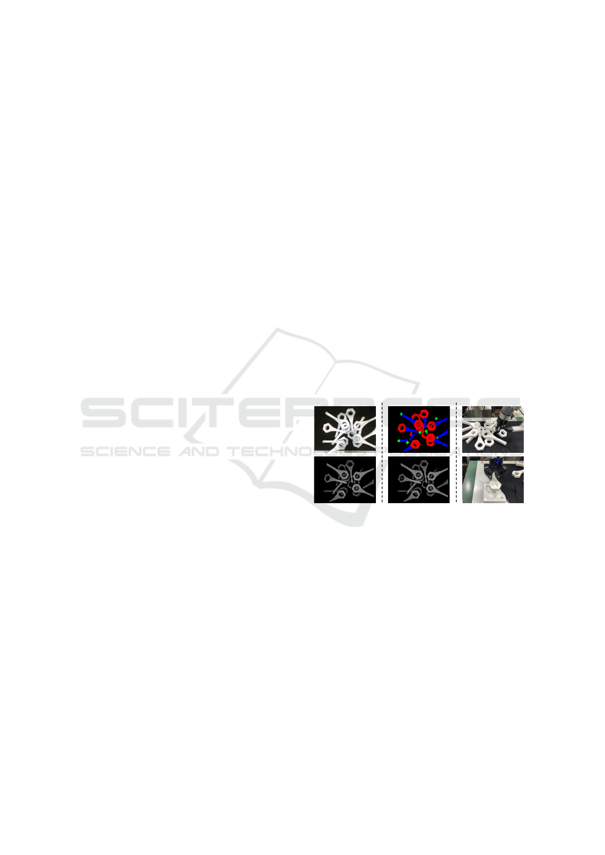
(b) RGB image of bin scene
(c) Result of function recognition
(d) Result of robot motion parameters estimation
rod A rod B rod C rod D
(a) Used part
Figure 8: Experimental result of robot motion parameters estimation. (a) Parts used in the experiment. (b) RGB image of bin
scene. (c) Result of function recognition. Blue refers to grasping function, red refers to big action assist function, green refers
to small action assist function. There are a few recognition errors, but most of them are correctly recognized. (d) Result of
robot motion parameters estimation. Red point and line show grasping point and blue point shows action point. This is the
estimation result when all components are included in Formula 2. The robot motion parameters were correctly estimated by
the proposed method.
Table 2: Result of ablation study.
Component of
Formula 1
Success rate
Functional
consistency
Object
recognition
rod A rod B rod C rod D Mean
✓ ✓ 86% 78% 88% 74% 81.5%
✓ 78% 74% 80% 78% 77.5%
✓ 78% 74% 76% 78% 76.5%
part in that state. The second point is when the parts
are intricately entangled with other parts. In this case,
when robot lifts a part, the entanglement causes the
part to drop. It is necessary to solve the problem using
related work(Zhang et al., 2021) or to devise grasping
strategies such as grasping the parts on top.
In future work, we will propose a method for es-
timating grasping points for parts that are easy to as-
semble from a bin scene. The grasping point is esti-
mated by our current method without considering the
ease of assembly, unlike humans. Ease of assembly
will be defined by us and the grasping point will be
estimated accordingly.
6 CONCLUSION
In this paper, we proposed a method for estimating
robot motion parameters required for parts assembly
from a bin scene. Each part has a role referred to as
VISAPP 2023 - 18th International Conference on Computer Vision Theory and Applications
526

(a) Approach part
(b) Grasp
(c) Pick up
(d) Insert
Figure 9: State of object assembled by robot. (a) Robot
approaches the grasping point estimated by the proposed
method. (b) The part is grasped by the robot. (c) Robot
pick up the part. (d) The robot inserts the carried parts into
the shaft.
a “function” such as “to be grasped” or “to be assem-
bled with other parts” for each region. We defined a
novel idea of functional labels and their consistency in
industrial parts. Functional consistency is used in the
proposed method as a cue, robot motion parameters
are estimated on the basis of relationship between pa-
rameters and functions. In an experiment using con-
necting rods, the average success rate was 81.5%. The
effectiveness of the proposed method was confirmed
from the ablation studies and comparison with related
work. The proposed method has a higher success rate
than methods that do not use function and functional
consistency, these are especially important concepts.
In future work, we will propose a method for estimat-
ing grasping points for parts that are easy to assemble
from a bin scene.
ACKNOWLEDGEMENTS
This paper is based on results obtained from a
project, JPNP20006, commissioned by the New En-
ergy and Industrial Technology Development Organi-
zation (NEDO).
REFERENCES
Akizuki, S. and Hashimoto, M. (2020). Detection of seman-
tic grasping-parameter using part-affordance recogni-
tion. In In International Joint Conference on Com-
puter Vision, Imaging and Computer Graphics Theory
and Applications(VISAPP)., pages 470–475.
Araki, R., Hasegawa, T., Yamauchi, Y., Yamashita, T., Fu-
jiyoshi, H., Domae, Y., Kawanishi, R., and Seki, M.
(2018). Grasping detection using deep convolutional
neural network with graspability. In Journal of the
Robotics Society of Japan, volume 36, pages 559–566.
Ardon, P., Pairet, E., Petrick, R., Ramamoorthy, S., and Lo-
han, K. (2020). Self-assessment of grasp affordance
transfer. In Proceedings of IEEE/RSJ International
Conference on Intelligent Robots and Systems (IROS),
pages 9385–9392.
Chu, F.-J., Xu, R., and Vela, P. (2019a). Learning affordance
segmentation for real-world robotic manipulation via
synthetic images. In IEEE Robotics and Automation
Letters, volume 4, pages 1140–1147.
Chu, F.-J., Xu, R., and Vela, P. (2019b). Toward affordance
detection and ranking on novel objects for real-world
robotic manipulation. In IEEE Robotics and Automa-
tion Letters, volume 4, pages 4070–4077.
Domae, Y., Okuda, H., Taguchi, Y., Sumi, K., and Hi-
rai, T. (2014). Fast graspability evaluation on sin-
gle depth maps for bin picking with general grippers.
In Proceedings of IEEE International Conference on
Robotics and Automation (ICRA), pages 1997–2004.
Hamalainen, A., Arndt, K., Ghadirzadeh, A., and Kyrki,
V. (2019). Affordance learning for end-to-end visuo-
motor robot control. In Proceedings of IEEE/RSJ In-
ternational Conference on Intelligent Robots and Sys-
tems (IROS), pages 1781–1788.
He, K., Gkioxari, G., Dollar, P., and Girshick, R. (2017).
Mask r-cnn. In Proceedings of the IEEE international
conference on computer vision, pages 2961–2969.
Iizuka, M. and Hashimoto, M. (2018). Detection of seman-
tic grasping-parameter using part-affordance recog-
nition. In Proceedings of International Conference
on Research and Education in Mechatronics (REM),
pages 136–140.
Kokic, M., Stork, J., Haustein, J., and Kragic, D. (2017).
Affordance detection for task-specific grasping using
deep learning. In Proceedings of IEEE-RAS Interna-
tional Conference on Humanoid Robotics, pages 91–
98.
Liu, W., Anguelov, D., Erhan, D., Szegedy, C., Reed, S., Fu,
C., and Berg, A. (2016). Ssd: Single shot multibox
detector. In Proceedings of European conference on
computer vision (ECCV), pages 21–37.
Liu, W., Daruna, A., and Chernova, S. (2020). Cage:
Context-aware grasping engine. In Proceedings of
IEEE International Conference on Robotics and Au-
tomation (ICRA), pages 2550–2556.
Minh, C., Gilani, S., Islam, S., and Suter, D. (2020). Learn-
ing affordance segmentation: An investigative study.
In Proceedings of International Conference on Dig-
ital Image Computing: Techniques and Applications
(DICTA), pages 2870–2877.
Myers, A., Teo, C., Ferm
¨
uller, C., and Aloimonos, Y.
(2015). Affordance detection of tool parts from
geometric features. In Proceedings of IEEE In-
ternational Conference on Robotics and Automation
(ICRA), pages 1374–1381.
Qin, Z., Fang, K., Zhu, Y., Fei-Fei, L., and Savarese,
S. (2020). Keto:learning keypoint representations
for tool manipulation. In Proceedings of IEEE In-
Estimation of Robot Motion Parameters Based on Functional Consistency for Randomly Stacked Parts
527

ternational Conference on Robotics and Automation
(ICRA), pages 7278–7285.
Redmon, J., Divvala, S., Girshick, R., and Farhadi, A.
(2016). You only look once:unified, real-time ob-
ject detection. In Proceedings of the IEEE conference
on computer vision and pattern recognition (CVPR),
pages 779–788.
Song, S., Zeng, A., Lee, J., and Funkhouser, T. (2020).
Grasping in the wild: Learning 6dof closed-loop
grasping from low-cost demonstrations. In IEEE
Robotics and Automation Letters, volume 5, pages
4978–4985.
Suzuki, T. and Hashimoto, M. (2021). A method for trans-
ferring robot motion parameters using functional at-
tributes of parts. In Lecture Notes in Computer Sci-
ence, volume 13018, pages 154–165.
Turpin, D., Wang, L., Tsogkas, S., and Garg, S. D. A.
(2021). Gift: Generalizable interaction-aware func-
tional tool affordances without labels. In Robotics:
Science and Systems.
Xu, R., Chu, F.-J., Tang, C., Liu, W., and Vela, P. (2021).
An affordance keypoint detection network for robot
manipulation. In IEEE Robotics and Automation Let-
ters, volume 6, pages 2870–2877.
Yamanobe, N., Wan, W., Ramirez-Alpizar, I., Petit, D.,
Tsuji, T., Akizuki, S., Hashimoto, M., Nagata, K.,
and Harada, K. (2017). A brief review of affordance
in robotic manipulation research. In Journal of Ad-
vanced Robotics, pages 1086–1101.
Zhang, X., Koyama, K., Domae, Y., Wan, W., and Harada,
K. (2021). A topological solution of entanglement
for complex-shaped parts in robotic bin-picking. In
Proceedings of IEEE International Conference on
Automation Science and Engineering (CASE), pages
461–467.
Zhao, X., Cao, Y., and Kang, Y. (2020). Object affordance
detection with relationship-aware network. In Neu-
ral Computing and Applications, volume 32, pages
14321–14333.
VISAPP 2023 - 18th International Conference on Computer Vision Theory and Applications
528
