
A Tool for Supporting Round-Trip Engineering with the Ability to Avoid
Unintended Design Changes
Takahiro Yamazaki
1
, Takafumi Tanaka
2
, Atsuo Hazeyama
3 a
and Hiroaki Hashiura
4 b
1
Graduate School of Engineering, Nippon Institute of Technology,
4-1 Gakuendai, Miyashiro, Minami-Saitama, Saitama, Japan
2
College of Engineering, Tamagawa University, 6-1-1 Tamagawagakuen, Tokyo, Japan
3
Dept. of Information Science, Tokyo Gakugei University, 4-1-1 Nukuikitamachi, Koganei, Tokyo, Japan
4
Faculty of Advanced Engineering, Nippon Institute of Technology,
4-1 Gakuendai, Miyashiro, Minami-Saitama, Saitama, Japan
Keywords:
UML, Traceability, Round-Trip Engineering, Object-Oriented Design.
Abstract:
It is difficult to maintain consistency between artifacts in a round-trip engineering project, such as an agile
development method. In such software development projects, there is a method using traceability links as a
method for maintaining consistency between artifacts. A method for creating traceability links from design
artifacts to programs has been proposed in the past. However, few studies have proposed traceability links
from source code to UML artifacts. Round-trip engineering could involve the developer making changes to
the source code and applying those changes to the UML artifacts. The larger the system, the more difficult it
becomes to apply changes to the UML artifact. We believe that traceability from the program to UML artifacts
effectively addresses this problem. In this paper, we propose a traceability link method for programs to design
artifacts, develop a tool for supporting the method, evaluate its effectiveness, and identify the difficulties for
developers in manually modifying class diagrams.
1 INTRODUCTION
In recent years, agile development methods, e.g.
Scrum (Schwaber, 1995) are widely used to produce
software products in a short period. These methods
are expected to be utilized to reduce discrepancies in
perceptions with clients regarding artifacts. To use
these techniques, it is necessary to develop the soft-
ware by repeatedly going between design and coding
(round-trip engineering) (Sendall and K
¨
uster, 2004).
For example, suppose that a developer creates a pro-
totype of a program based on a design document and
presents it to a customer. The customer requests im-
provements, which the developers then reflect on the
design documents and programs. The project pro-
gresses through a series of iterations. On the other
hand, the repetitive back-and-forth between design
and coding, as described above, may lead to consis-
tency loss and integrity among artifacts. If this situa-
tion is left unchecked, the following additional prob-
lems may arise.
a
https://orcid.org/0000-0001-6583-1521
b
https://orcid.org/0000-0002-6325-4177
1. As the size of the design document increases, it
becomes more difficult for the developer to main-
tain consistency and integrity.
2. The records and contents of modifications are
stored only by the person in charge of the modifi-
cation, and other members can not grasp the con-
tents, which makes development and maintenance
difficult.
3. Since people’s memories typically fade over time,
the situation may arise where it is unclear where
the changes should be applied (Rempel and
Mader, 2017).
This study aims to solve the three aforementioned
problems by focusing on round-trip engineering in the
two processes of design and programming in the de-
velopment process. Specifically, the tool extracts dif-
ferences between design artifacts and elements in the
source code, and it highlights them on the design arti-
facts to encourage modification of the artifacts. In ad-
dition, the modification rates of fully automated tools
and semi-automated methods are compared when per-
forming the task of reflecting changes in the source
code to the class diagram to meet certain require-
Yamazaki, T., Tanaka, T., Hazeyama, A. and Hashiura, H.
A Tool for Supporting Round-Trip Engineering with the Ability to Avoid Unintended Design Changes.
DOI: 10.5220/0011667500003402
In Proceedings of the 11th International Conference on Model-Based Software and Systems Engineering (MODELSWARD 2023), pages 125-132
ISBN: 978-989-758-633-0; ISSN: 2184-4348
Copyright
c
2023 by SCITEPRESS – Science and Technology Publications, Lda. Under CC license (CC BY-NC-ND 4.0)
125

ments. We will identify whether there is a difference
in the acceptance of modifications to class diagrams
when the modification process requires changes to be
made to the class diagram for implementation reasons
or other reasons, or when programmers make changes
to the code without consulting development members.
2 RELATED WORK
This section mainly introduces research on traceabil-
ity. Yoshida et al.(Yoshida et al., 2020) focused on the
process of implementation source codes from a de-
sign artifacts created by a non-native English speaker.
They used Java Annotations (Oracle America, Inc.,
2021) to create traceability links for the different el-
ement names in the UML diagram and source code.
However, they only created traceability links from de-
sign artifacts to programs. Their tool can not be used
for round-trip engineering because it can not create
traceability links from programs to design artifacts.
Yu et al.(Yu et al., 2021) focused on Informa-
tion Retrieval(IR)-based traceability assurance be-
tween design artifacts and source code. They stated
that vocabulary mismatch between natural and pro-
gramming languages affects the accuracy of traceabil-
ity. They proposed a method that combines IR tech-
niques with common database statements between the
two artifacts. Their method has been shown to have
higher Precision and F-Measure values than Vector
Space Model(VSM), one of the IR techniques, in
traceability assurance experiments.
Jongeling et al.(Jongeling et al., 2021) proposed
model-source code synchronization in model-based
development round-trips. The tool identifies where
the source code has been modified and then outputs
the differences between the model and the source
code to XML to show the developer where the
changes have been made. In contrast to their study,
our study has advantages. That study shows the dif-
ferences directly in the modeling tool, which reduces
the time and effort required to compare the model to
the source code.
Ciccozzi and Sjodin (Ciccozzi et al., 2011) state
the following in MDE in embedded systems. They
state that data outside of system functionality (e.g.,
memory usage) is difficult to predict and that the
results obtained by execution should be reflected in
the design artifact. To address this problem, they
proposed the Back-Annotation model for propagat-
ing non-system function data to design artifacts. The
difference with this study is the purpose of propaga-
tion. The Back-Annotation model was intended to
satisfy requirements by feeding back information col-
lected at runtime to the design. In contrast, this study
aims to meet requirements by preventing inconsisten-
cies between artifacts and avoiding unintended design
changes.
In addition, Arima et al.(Arima et al., 2021)
stated that human maintenance of artifacts is time-
consuming, labor-intensive, and correction omissions
occur. To solve these problems, they proposed RE-
TUSS, which maintains traceability between UML di-
agrams and source code in realtime. They focused on
the time difference in maintaining traceability when
using RETUSS and when using only Enterprise Ar-
chitect(EA) (Sparx Systems Pty Ltd., 2022) and a
text editor. Their studies have evaluated the degree to
which traceability can be ensured, but have not con-
ducted a quantitative evaluation by comparing it with
manual work, as will be done here.
Aung et al.(Aung et al., 2020) conducted a sys-
tematic literature review related to automatic trace-
ability link recovery approaches with a focus on
Change Impact analysis(CIA). Their review indicated
that few traceability studies focused on designing and
testing impact analysis sets, they stated that this is
presumably due to the small data set. We believe
one of the reasons for the paucity of studies covering
design artifacts is that modern software development
projects based on agile methodologies omit compre-
hensive documentation traceability to design artifacts,
which has not been discussed recently, is important as
agile development becomes more popular.
Rosca and Domingues (Rosca and Domingues,
2021) compared the performance of round-trip engi-
neering in three modeling tools. The three tools being
compared are Papyrus, Modelio and Visual Paradigm.
The three tools showed a success rate of more than
80% in direct measurement metrics such as the num-
ber of methods used. They states that qualitative as-
sessments are needed to complement quantitative as-
sessments. It is important that developers are able to
use round-trip engineering tools and still make the in-
tended changes.
3 PROPOSED METHOD
This study proposes a method for creating traceability
links from programs to design artifacts. The method
deals with the class diagram as a design artifact, and
the source code written in Java.
1. The tool extracts differences between source code
and class diagram.
2. The tool suggests to developers how to fix the dif-
ferences.
MODELSWARD 2023 - 11th International Conference on Model-Based Software and Systems Engineering
126
3. The developer selects the appropriate modifica-
tion from the suggested ones and modifies the
class diagram.
The authors believe that in the round-trip engi-
neering addressed in this study, developers will en-
counter the problem of inconsistency between class
diagrams and source code. Two issues are discussed
here as examples: first, developers miss inconsisten-
cies between artifacts due to visual checks; second,
minor specification changes during round-trip engi-
neering.
The former is the problem of developers being un-
able to maintain detailed consistency between class
diagrams and source code once the scale of develop-
ment exceeds a certain level. Such a problem occurs,
for example, when a developer mistakes the “e” as “a”
in the “Scanner” class. Although “Scannar” is not a
correct English word, it is easy to overlook such mis-
takes since consistent use of such a name in a program
will not cause program execution problems. The lat-
ter problem occurs when a developer finds a design
error during programming and corrects it. To give a
concrete example, a class “Input” that specializes in
input is created in the design stage, and then in the
programming stage, it is realized that it is better to
create this class as an input/output class, so the pro-
gram specification is changed and the class name in
the program is also changed to “InOut” to match the
actual situation. In such cases, a high-level decision is
required as to whether the design should be changed
in the priority of the program or whether the design
should be modified to maintain the original program
structure.
Based on these two points, the proposed method
uses a semi-automatic modification approach to main-
tain consistency and integrity between the class dia-
gram and the source code, in which a tool presents a
list of proposed modifications, and the developer se-
lects one of them. This also allows the developer to
use a modification other than the suggested candidate
(e.g., to change both the design and the program). Ex-
isting modeling tools often cannot integrate with other
tools or provide feedback to developers on problems
(Agner and Lethbridge, 2017) Therefore, we decided
to implement such a function in our modeling tool.
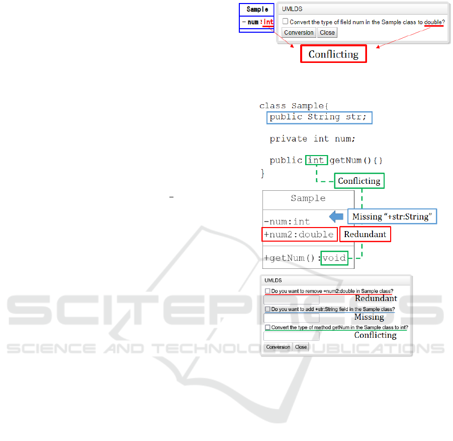
Figure 1 shows an image of the presentation of candi-
date modifications to a class diagram.
3.1 Differences in Type Definitions
The consistency issues a between class diagram and
source code, which are treated in this study, are di-
vided into the following three categories according to
the state in which there is a difference between them.
Figure 1: An example of displaying candidates for correc-
tion on a class diagram.
Figure 2: An example of consistency issues between a class
diagram and source code.
A) Redundant: Elements exist in the class diagram
but not in a source code (e.g. the red box in Fig-
ure 2).
B) Missing: Elements exist in the source code but not
in a class diagram (e.g. the blue box in Figure 2).
C) Conflicting: Elements having the same name but
with conflicting qualifiers or types (e.g. the green
box in Figure 2).
3.2 How to Indicate Differences
Between a Class Diagram and
Source Code
This section describes how to indicate the differences
described in the previous section. In this method, dif-
ferences are indicated to the developer in red letters
on the class diagram. Missing differences that can not
be shown on the class diagram are indicated in the di-
alog. An example of a presentation to users is shown
A Tool for Supporting Round-Trip Engineering with the Ability to Avoid Unintended Design Changes
127
in Figure 2. The differences offered by the proposed
tool are defined as follows:
I Stereotype: Interface, Abstract
II Class Name
III Field: Modifier, Element Name, Type
IV Method: Modifier, Element Name, Return Value
Type
V Parameter: Parameter Name, Type
3.3 Storing Correction History
As exemplified in Section 3, modifications to artifacts
require a high degree of judgment, so discussions
are held among developers. After discussions among
the developers, either the “Conversion button” or the
“Close button” in the dialog shown in Figure 2 can
be selected. When the conversion button is selected,
the process of saving the dialog state is executed. The
reason for storing the dialog content is that by storing
the correction history, it is possible to reuse the crite-
ria for making changes when similar problems occur
among developers. Correction histories to be stored
are as follows:
1. What types of correction method the user has cho-
sen (check box status).
2. A detailed description of the difference. As an
example, the text of the dialog shown in Figure 2
is saved.
3. Timestamps of when the dialog was opened and
closed.
If the Close button is selected, the tool closes the dia-
log without saving the information.
4 TOOL IMPLEMENTATION
The proposed method uses Eclipse for writing source
code and KIfU(Tanaka et al., 2018) for UML model-
ing tool. The tool supporting this method consists of a
plug-in part of Eclipse and an extension part of KIfU.
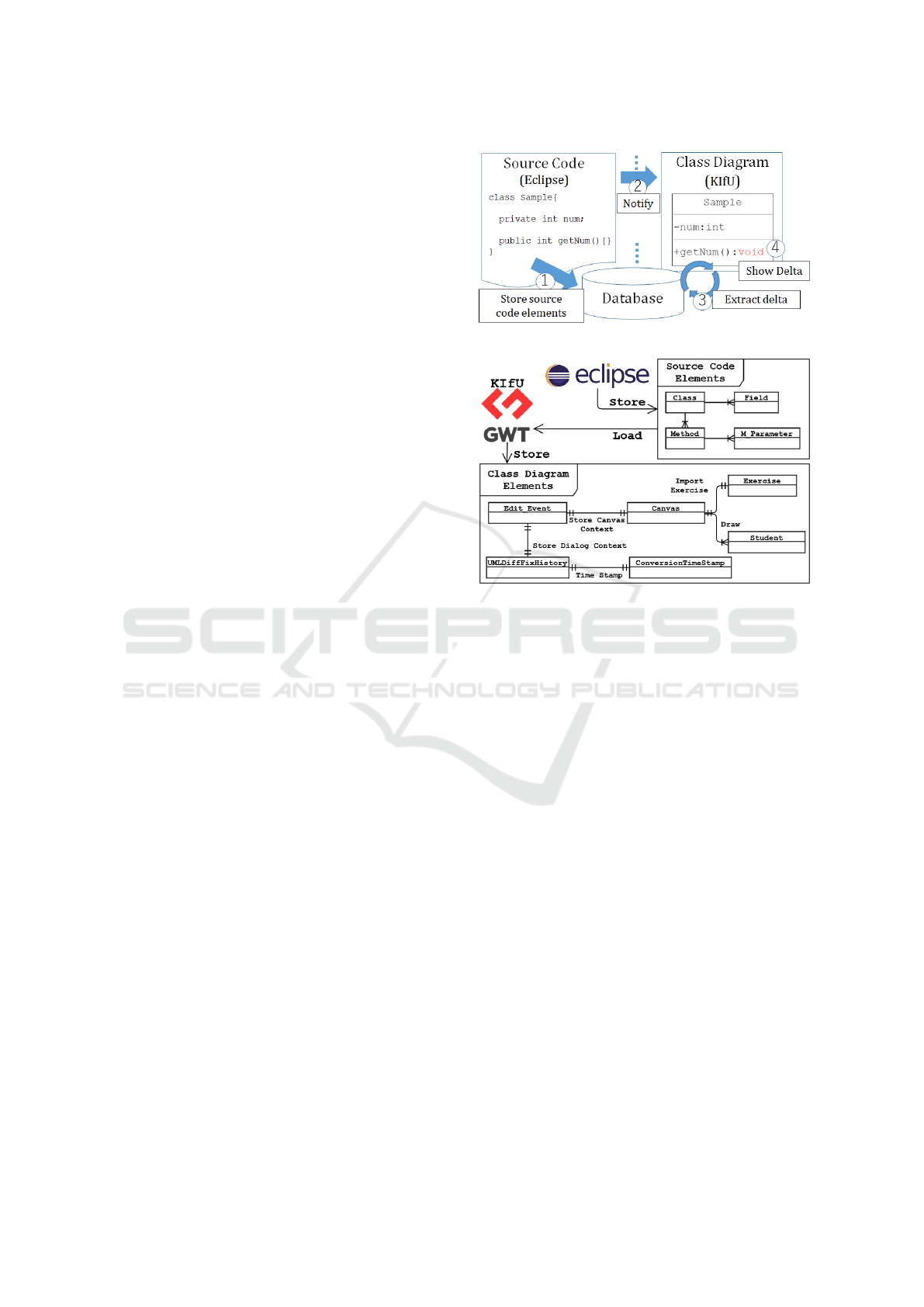
Figure 3 and Figure 4 show an overview of the tool
and a meta-model used by the tool, respectively.
The specific processing steps of the tool are de-
scribed below:
1) When the Eclipse plug-in detects that a change
has been made to the source code, using parser,
elements are extracted from the source code and
stored in a database.
2) The Eclipse plug-in notifies KIfU using
JeroMQ(Trevorbernard, 2021) when 1) is
completed.
Figure 3: An overview of the tool implementation.
Figure 4: A meta-model used by the proposed tool.
3) When KIfU receives the notification in 2), it de-
tects the difference between the source code stored
in the database in 1) and the class diagram being
edited in KIfU. Elements of the source code and
class diagram are stored as strings in the follow-
ing form. ‘ClassNamne!FieldName or Method-
Name}Type or modifier.’ The detection work uses
Java’s String.equals to exhaustive search.
4) KIfU displays the differences detected in 3) on the
class diagram (Figure 2).
5) KIfU presents a list of modifications (Figure 1) to
the developer based on the differences. The devel-
oper can automatically modify the class diagram
by selecting the appropriate checkboxes.
The list of modifications presented by the tool is
generated based on the element names and according
to the following rules for each type of difference be-
tween artifacts described in section 3.1.
a) Redundant: Deleting redundant elements from the
class diagram.
b) Missing: Adding missing elements to the class di-
agram.
c) Conflicting: Modifiers and types are changed to
match the corresponding source code.
MODELSWARD 2023 - 11th International Conference on Model-Based Software and Systems Engineering
128

5 EXPERIMENT
Evaluation experiments were conducted to determine
if the method can prevent unintended changes. In
the experiment, the correction rate (the rate at which
inserted defects were corrected in accordance with
the prepared requirements) of inconsistency between
class diagram and source code were investigated for
two correction tasks: Comparison Experiment 1. Par-
ticipants manually fix problems both with and with-
out implementation convenience. Comparison Exper-
iment 2. Comparison of correction rates the between
automatic correction tool and the manual method.
Participants are fourth-year undergraduate students
from Nippon Institute of Technology who enrolled
in the department of Information Systems and Me-
dia Design, and five graduate school students from the
Graduate School of Engineering, Nippon Institute of
Technology. All participants have basic UML knowl-
edge and Java programming experience at an under-
graduate level.
The procedure of the experiment is described be-
low. First of all, participants are given an assignment
that consists of a class diagram and Java source code.
Certain defects are inserted into the assignment be-
forehand to cause limitation between the source code
and the class diagram. In addition, we adjusted the
number of elements in the assignment and the num-
ber of inserted defects to equalize the complexity and
difficulty level. These are shown in Tables 1 and Ta-
bles 2, respectively. In this experiment, the number
of defects for which source code changes must be
accepted is six or less. This is because we believed
that in actual development, design artifacts should be
sufficiently discussed to meet the requirements that
there would be only a few situations in which changes
would be accepted.
The procedure for Comparison Experiment 1 is as
follows. First, participants are given an assignment
consisting of a class diagram, Java source code and
a requirement document for each problem. This is
the common part of problems 1 and 2. The differ-
ence between problems 1 and 2 is that in problem 1,
the reason for the changes made to the code is given;
in problem 2, the reason for the changes made to the
code is not given. Problem 1 is a situation where
the programmer has a reason for wanting to make
changes to the artifacts for programming reasons and
discusses whether the changes meet the requirements.
Problem 2 posits a situation in which a programmer
makes changes without consulting the members of the
team, therefore without their permission/agreement.
We also asked the participants to describe on the tool
any reasons for acceptance/rejection.
Table 1: Number of scales for each problem.
# Classification
Problem1
(Calculator)
Problem2
(Task Management)
1 of Classes 12 12
2 of Fields 17 27
3 of Methods 40 34
4 of Parameters 26 54
Table 2: Number of defects in each defect type.
# Classification
Problem1 and 2
Match to
Class Diagram
Match to
Source Code
1 Missing 6 2
2 Redundant 6 2
3 Conflicting 6 2
4 Total Defects 18 6
5 of Class 1 0
6 of Field 7 2
7 of Method 7 2
8 of Parameter 3 2
9 Total Elements 18 6
Comparison Experiment 2 compares the modifi-
cation rate when the automatic modification tool re-
verse engineers the code and reflects the changes in
the class diagram with the results of Comparison Ex-
periment 1. Comparison Experiment 2 uses the same
problem as Comparison Experiment 1. IBM Rhap-
sody (IBM Corporation, 2020) was used as the auto-
matic correction tool.
6 RESULTS AND DISCUSSION
Two Research Questions(RQs) were established to
evaluate the experiment.
RQ-1. What differences appear in the manual when
given situations are different?
RQ-2. What are the characteristics of an automated
correction tool versus a manual correction
process?
Refernece Table 3 to answer the RQ. Accuracy is the
percentage of correct decisions to accept or reject.
Precision is the percentage of defects that actually
needed to be accepted out of those judged to be ac-
ceptable. Recall is the percentage of defects that need
to be accepted and that are accepted. The results of
aggregating these values are shown in Tables 4, 5
and 6 respectively. The results of the calculations are
shown in Table 7 and Table 8.
Table 3: Mixture matrix in manual work.
Participants
IBM Rhapsody
Accept Reject
Actually
Inserted Defect TP FN
No Defect FP TN
A Tool for Supporting Round-Trip Engineering with the Ability to Avoid Unintended Design Changes
129

Table 4: Result with implementation limitation.
# Data item TP FP FN TN
1 Missing 17 30 1 24
2 Redundant 16 18 2 27
3 Conflicting 13 21 5 33
4 Class flaw question
5 Field 17 29 1 34
6 Method 12 15 6 39
7 Parameter 36 15 2 12
Table 5: Result without implementation limitation.
# Data item TP FP FN TN
1 Missing 14 31 4 23
2 Redundant 9 20 9 34
3 Conflicting 8 30 10 24
4 Class 0 5 0 4
5 Field 10 34 8 29
6 Method 12 31 6 32
7 Parameter 10 12 8 15
First, we answer about RQ1 using Table 7 of the
results of Comparison Experiment 1. Regarding the
Precision rate, the value for both the elemental species
and the defective species was about 10% higher for
the one with implementation limitation. It is interest-
ing to note that the highest value is 50% and about
half of the corrective work is erroneous corrections,
even if there is an implementation limitation. This
shows that implementation convenience can have a
bad effect on designers, causing them to make poor
decisions. Regarding the Recall rate, the correction
rate was about 25% higher for those with clues. The
Recall results show that there is a significant differ-
ence in the impact of implementation limitation on
the redundant or conflicting, parameters and fields.
As for the Recall, it must be taken into account that
the difference in values can be drastic because of the
small number that must be accepted. Finally, for the
F-values, the sum of the defective species and the el-
emental species differed by about 15% each. The ac-
curacy is higher when there in implementation limita-
tion left by the programmer, with a difference of 20%
with respect to conflicting items, redundant items, and
fields items. In contrast, those that do not have a
strong effect of opinion on implementation are Miss-
ing items, at 8%.
Table 6: Results of IBM Rhapsody(IBM Corporation,
2020).
# Data item TP FP FN TN
1 Missing 4 12 0 0
2 Redundant 4 10 0 0
3 Conflicting 4 12 0 0
4 Class 0 1 0 0
5 Field 4 14 0 0
6 Method 4 13 0 0
7 Parameter 4 6 0 0
The results for Missing items have the smallest
differences for any of the items. This is because it is
normal to assume that if careful discussions are made
during design, there will be nothing missing in that
design artifact, and the designer’s desire is to have the
product made as designed, even if the implementer’s
convenience in involved. As an example, suppose
there is a class that sorts a list, and the implemen-
tor wants to add an instance field, tmp, for sorting.
However, the designer’s thinking assumes that it is not
necessary to add extra variables by using the standard
library’s sort(), etc., rather than creating a sorting al-
gorithm on his own, which would easily lead to a re-
jection decision that does not add any new elements.
Therefore, it can be said that implementation conve-
nience has no effect on missing elements. In con-
trast, the results for redundant items have large differ-
ences in all items. The participant confirmed imple-
mentation limitation such as ”not used during the im-
plementation phase” and determined that it would be
more effective to remove variables and functions that
were not used during development in order to facili-
tate understanding of the overall system during sub-
sequent maintenance work. In this experiment, par-
ticipants were given implementation convenience as a
material for comparison, but the results may change
if participants are given other materials (such as ac-
tually having them discuss with someone). It must
also be discussed whether the implementation conve-
nience given was appropriate.
Next, we answer the question about RQ2 using the
results of Comparison Experiment 2. Comparative re-
sults are shown in Table 8. One of the characteristics
of the fully automated system is that it has a 100%
recall rate, which means that nothing can be missed.
In contrast, the precision rate is low at 30%. This is
due to the fact that changes were made to unnecessary
parts of the class diagram. When looking at F-Values,
manual work is about more than 50% more accurate,
while automatic correction tools are about more than
40% accurate. Thus, it can be said that manual work
is better at making the intended corrections. How-
ever, the result is that the fewer changes that must be
applied to the class diagram relative to the number
of elements that have been modified, the more likely
it is that the automatic modification tool will make
changes to the class diagram that the developer did
not intend.
IBM Rhapsody has the function to perform round-
trip. We believe there are two caveats to the de-
veloper’s use of modeling tools to conduct round-
trip. The first caveat is the way the tool shows the
elements. When using List as a field in the IBM
Rhapsody used in the experiment, the List field is
MODELSWARD 2023 - 11th International Conference on Model-Based Software and Systems Engineering
130

Table 7: Result of with implementation limitation and without.
Accuracy Precision Recall F-value
With Without With Without With Without With Without
Missing 56.9% 51.4% 36.2% 31.1% 94.4% 77.8% 52.3% 44.4%
Redundant 68.3% 59.7% 47.1% 31.0% 88.9% 50.0% 61.5% 38.3%
Conflicting 63.9% 44.4% 38.2% 21.1% 72.2% 44.4% 50.0% 28.6%
Total Defects 61.8% 51.9% 38.7% 27.7% 85.2% 57.4% 53.2% 37.3%
of Field 63.0% 48.1% 37.0% 22.7% 94.4% 55.6% 53.1% 32.3%
of Method 63.0% 54.3% 33.3% 27.9% 66.7% 66.7% 44.4% 39.3%
of Parameter 62.2% 55.6% 51.6% 45.5% 88.9% 55.6% 65.3% 50.0%
Total Elements 62.8% 51.9% 39.8% 28.1% 83.3% 59.3% 53.9% 38.1%
Table 8: Result of with implementation limitation and IBM Rhapsody.
Accuracy Precision Recall F-value
With
IBM Rhapsody
With
IBM Rhapsody
With
IBM Rhapsody
With
IBM Rhapsody
Missing 56.9% 25.0% 36.2% 25.0% 94.4% 100.0% 52.3% 40.0%
Redundant 68.3% 28.6% 47.1% 28.6% 88.9% 100.0% 61.5% 44.4%
Conflicting 63.9% 25.0% 38.2% 25.0% 72.2% 100.0% 50.0% 40.0%
Total Defects 61.8% 26.1% 38.7% 26.1% 85.2% 100.0% 53.2% 41.4%
of Field 63.0% 22.2% 37.0% 22.2% 94.4% 100.0% 53.1% 36.4%
of Method 63.0% 23.5% 33.3% 23.5% 66.7% 100.0% 44.4% 38.1%
of Parameter 62.2% 40.0% 51.6% 40.0% 88.9% 100.0% 65.3% 57.1%
Total Elements 62.8% 26.1% 39.8% 26.1% 83.3% 100.0% 53.9% 41.4%
not drawn in the class diagram. When List is used
as a field in the IBM Rhapsody used in this experi-
ment, the information is expressed as a relation to the
package in which the List is stored, rather than be-
ing drawn as a List field in the class diagram. The
developer must search through a number of associa-
tions to ensure that the List field is consistent between
the code and the class diagram. IBM Rhapsody has a
function to record the history of round trips in text
form, allowing developers to check where changes
have been made. But it is not possible to visualize the
differences on the model in this method. The second
caveat is when multiple developers make changes to
the same artifact. If two developers make changes to
the same source code, the modeling tool will reflect
the second developer’s changes in the model. Both
changes made by the first person and the second per-
son have implementation ramifications, and the tool
should decide what to reflect in the model based on
discussions among the developers, rather than imme-
diate reflection.
7 THREATS TO VALIDITY
1. Description of Intended Change: Although this
study assumes that programmers leave written
reasons for changes they want to make to the
source code, we received comments from exper-
imental collaborators that the reasons for changes
they made to the code were difficult to understand.
We believe this is a burdensome task for the de-
signer to read the text and extract information use-
ful in determining acceptance or non-acceptance.
Safwan and Servant (Safwan and Servant, 2019)
subdivides the rationale for a developer’s code
commits into 15 pieces. Of the 15 elements, the
tool can already propose Location and Modifica-
tion in this method. We believe that other items
should also be communicated to the designer to
improve the acceptance decision
2. Only project scale and simple defects can be ad-
dressed: In this method, all elements in the class
diagram and source code are searched in order to
detect differences. If the tool targets thousands
or tens of thousands of artifacts, it is expected to
take an enormous amount of time to detect dif-
ferences. A method is needed to identify the dif-
ference locations, as in Jongeling et al.(Jongeling
et al., 2021). This method can only handle simple
differences such as the element type of a class.
Class relationships such as inheritance, multiplic-
ity, etc. must also be addressed.
8 CONCLUSION
In this study, we have developed a tool that shows
developers the differences between source code and
class diagram. A comparison of the correction rates
of semi-automatic and fully automatic tools in con-
ducted. The results quantitatively showed that the au-
tomatic correction tool does not overlook and accepts
defects that do not need to be accepted. In contrast,
semi-automatic corrections, on the other hand, can
A Tool for Supporting Round-Trip Engineering with the Ability to Avoid Unintended Design Changes
131

discover and accept changes necessitated by imple-
mentation reasons, but implementation reasons can
also work in the wrong direction. We investigated the
difference in correction rates in semi-automatic cor-
rection work with and without implementation con-
venience. A characteristic result was that the value of
Missing made no difference in the revision decision
whether there was an implementation convenience or
not. In the future, we will focus on saving the change
history. Currently, we have been able to create a func-
tion to save the change history on the tool. The eval-
uation method, the content of the stored information,
and the reuse of the reasons will be discussed.
ACKNOWLEDGEMENTS
This work was supported by JSPS KAKENHI Grant
Numbers 21K12179.
REFERENCES
Agner, L. T. W. and Lethbridge, T. C. (2017). A survey of
tool use in modeling education. In 2017 ACM/IEEE
20th International Conference on Model Driven En-
gineering Languages and Systems (MODELS), pages
303–311.
Arima, K., Katayama, T., Kita, Y., Yamaba, H., Aburada,
K., and Okazaki, N. (2021). Extension of the func-
tion to ensure real-time traceability between UML se-
quence diagram and Java source code on RETUSS.
Advances in Artificial Life Robotics, 2:254–258.
Aung, T. W. W., Huo, H., and Sui, Y. (2020). A liter-
ature review of automatic traceability links recovery
for software change impact analysis. In 28th Interna-
tional Conference on Program Comprehension, ICPC
’20, page 14–24, New York, NY, USA. Association
for Computing Machinery.
Ciccozzi, F., Cicchetti, A., and Sjodin, M. (2011). Towards
a round-trip support for model-driven engineering of
embedded systems. In 2011 37th EUROMICRO Con-
ference on Software Engineering and Advanced Ap-
plications, pages 200–208.
IBM Corporation (2020). IBM Engineering Systems De-
sign Rhapsody 9.0.1. https://www.ibm.com/products/
systems-design-rhapsody.
Jongeling, R., Bhatambrekar, S., Lofberg, A., Cicchetti, A.,
Ciccozzi, F., and Carlson, J. (2021). Identifying man-
ual changes to generated code: Experiences from the
industrial automation domain. In 2021 ACM/IEEE
24th International Conference on Model Driven En-
gineering Languages and Systems (MODELS), pages
35–45.
Oracle America, Inc. (2021). Annotations – the
Java language specification, Java SE 17 edi-
tion. https://docs.oracle.com/javase/specs/jls/se17/
html/jls-9.html#jls-9.7.
Rempel, P. and Mader, P. (2017). Preventing defects: The
impact of requirements traceability completeness on
software quality. IEEE Transactions on Software En-
gineering, 43(8):777–797.
Rosca, D. and Domingues, L. (2021). A systematic com-
parison of roundtrip software engineering approaches
applied to UML class diagram. Procedia Computer
Science, 181:861–868.
Safwan, K. A. and Servant, F. (2019). Decomposing the
rationale of code commits: The software developer’s
perspective. In 2019 27th ACM Joint Meeting on Eu-
ropean Software Engineering Conference and Sym-
posium on the Foundations of Software Engineer-
ing, ESEC/FSE 2019, page 397–408, New York, NY,
USA. Association for Computing Machinery.
Schwaber, K. (1995). Scrum development process: Ad-
vanced development methods. In OOPSLA’95 Work-
shop on Business Object Design and Implementation,
pages 117–134.
Sendall, S. and K
¨
uster, J. (2004). Taming model round-
trip engineering. In Proceedings of Workshop on
Best Practices for Model-Driven Software Develop-
ment (satellite event of the 19th Annual ACM Confer-
ence on Object-Oriented Programming, Systems, Lan-
guages, and Applications (OOPSLA 2004)), Vancou-
ver (Canada).
Sparx Systems Pty Ltd. (2022). Enterprise Architect. https:
//sparxsystems.com/products/ea/.
Tanaka, T., Hashiura, H., Hazeyama, A., Komiya, S., Hi-
rai, Y., and Kaneko, K. (2018). Learners self checking
and its effectiveness in conceptual data modeling ex-
ercises. IEICE Transactions on Information and Sys-
tems, E101.D(7):1801–1810.
Trevorbernard (2021). Java-ZeroMQ. https://zeromq.org/
languages/java/.
Yoshida, Y., Hashiura, H., Tanaka, T., Hazeyama, A., and
Takase, H. (2020). A proposed method for recov-
ering traceability linksbetween documents and codes
written in different languages. In The RISP Interna-
tional Workshop on Nonlinear Circuits, Communica-
tions and Signal Processing 2020 (NCSP 20), pages
1–4.
Yu, L., Li, Y., Feng, Y., and Qi, C. (2021). Traceabil-
ity method between design documents and source
codes based on SQL dependency. In 2021 20th In-
ternational Symposium on Distributed Computing and
Applications for Business Engineering and Science
(DCABES), pages 144–147.
MODELSWARD 2023 - 11th International Conference on Model-Based Software and Systems Engineering
132
