
Design of Inner Baffle Array for Compact Multi-Aperture Off-Axis
Optical System
Peixian Han
1,2,3,4
, Junli Guo
1,2,3,4
, Meili Zhang
1,4
, Bingxu Chen
1,4
, Ge Ren
1,2,3,4,*
and Yong Liu
2
1
Key Laboratory of Optical Engineering, Chinese Academy of Sciences, Chengdu 610209, China
2
School of Optoelectronic Science and Engineering, University of Electronic Science and Technology of China,
Chengdu 611731, China
3
University of Chinese Academy of Sciences, Beijing 100039, China
4
Institute of Optics and Electronics, Chinese Academy of Sciences, Chengdu 610209, China
Keywords: Multi-Aperture Optical System, Stray Light Analysis, BRDF Measurement, Inner Baffle Array Design.
Abstract: In order to realize the light and miniaturization of the imaging telescope of the optical communication system,
a design method of the inner baffle array of the compact multi-aperture off-axis beam transmission system is
developed in this paper. This method mainly deduces the inclination angle of the inclined section of the inner
baffle of the multi-aperture off-axis beam transmission system by the method of spatial analytic geometry,
and establishes a compact three-aperture inner baffle array in the off-axis beam transmission system by using
3D modeling software. The bidirectional reflection distribution function (BRDF) of inorganic oxidized Al/SiC,
oxidized TC4, untreated carbon fiber reinforced plastic (CFRP), and indene steel was tested by the angular
determination scatterometer, and the scattering data of CFRP with the highest cost performance was put into
the stray light analysis software to simulate the point source transmittance (PST) of the inclined section and
the flush section of the baffle tube array. The simulation results show that the proposed method can effectively
improve the cross-talk of external stray light between the sub-aperture of the multi-aperture off-axis beam
transmission system.
1 INTRODUCTION
Optical communication has the advantages of high
speed, low power consumption and high security,
which is an effective means to achieve satellite-
ground big data communication in the future. After
reaching the receiving plane, the signal light emitted
by the traditional single-aperture imaging system is
severely distorted, and the energy concentration is
low. Using beam synthesis (coherent synthesis or
incoherent synthesis) method to combine multiple
beams to realize beam array multi-aperture
transmission system is an important way to
effectively overcome the nonlinear effect of beam
gain medium, overcome the influence of atmospheric
turbulence phase, and obtain higher power. Space
systems have strict restrictions on volume and weight,
so compact, light and miniaturization are the
development trends of space systems. The compact
multi-aperture optical communication system can
reduce the size of the system structure, reduce the cost
*
Corresponding author: renge@ioe.ac.cn
of the system, and improve the cost performance of
the system while obtaining high power and
maintaining good beam quality.
Stray light refers to the light that diffuses outside
the imaging light in the optical system on the surface
of the detector, and the light that reaches the detector
by abnormal optical path. During imaging, the system
must have a strong ability to exclude stray light,
otherwise sunlight or other stray light sources will
sink the imaging beam. If the stray light is not
properly eliminated, it may result in a false response
or noise flooding the real light signal due to the low
illuminance and large dynamic range of targets. At
the same time, the space target detection camera
working outside the atmosphere would inevitably be
disturbed by the sunlight, the moon, the ground light,
the outer surface of spacecraft and the scattering of
components, resulting in an increase in the image
surface stray light gray scale, and the image surface
illumination distribution was not uniform, which
52
Han, P., Guo, J., Zhang, M., Chen, B., Ren, G. and Liu, Y.
Design of Inner Baffle Array for Compact Multi-Aperture Off-Axis Optical System.
DOI: 10.5220/0011665200003408
In Proceedings of the 11th International Conference on Photonics, Optics and Laser Technology (PHOTOPTICS 2023), pages 52-58
ISBN: 978-989-758-632-3; ISSN: 2184-4364
Copyright
c
2023 by SCITEPRESS – Science and Technology Publications, Lda. Under CC license (CC BY-NC-ND 4.0)
affected the improvement of signal-to-noise ratio and
the identification of debris.
Compact multiple aperture off-axis imaging
system between each sub aperture has the problem of
crosstalk of stray light outside the field of view. The
traditional inner baffle array with flush section has
poor suppression effect on the out-of-field stray light
from adjacent sub-aperture. The stray light outside
the field of view of adjacent aperture will pass
through the inner baffle and enter the subsequent
imaging optical path, and there is light leakage
phenomenon. In this paper, in view of the
phenomenon that the stray light outside the field of
view between the sub apertures of the compact multi-
aperture off-axis imaging system crosstalk with each
other, a new design method for the inner baffle array
is invented, taking a set of three aperture compact off-
axis beam narrowing system as an example, which
successfully prevents the stray light lines outside the
field of view from adjacent apertures from passing
through the inner baffle and entering the subsequent
imaging optical path.
2 OPTICAL SYSTEM
STRUCTURE
The compact multi-aperture optical communication
system consists of three main optical systems and
subsequent optical systems. The main optical system
adopts the afocal Mersenne-Cassegrain design, which
is conducive to the assembly of the system and the
optical path docking between various subsystems
after the disassembly and assembly of the whole
machine. Both the primary mirror (PM) and the
secondary mirror (SM) are off-axis paraboloids,
forming an off-axis afocal-beam, which can reduce
the difficulty of detection and processing of large-
diameter PM and convex SM. The optical structure
layout of a single aperture is shown in Figure 1. The
structure layout of the three-aperture optical system is
shown in Figure 2.
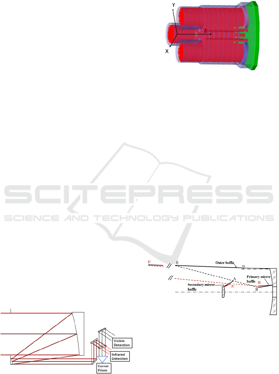
Figure 1: Schematic optics layout of the common optical
path design.
Figure 2: The structure layout of the three-aperture imaging
system.
3 MODEL GEOMETRY DESIGN
AND VERIFICATION
3.1 The Two-Stage Fore Baffle Design
Baffles are employed to eliminate the direct light that
can reach the detector without any scattering. For a
two-mirror optical system, the most common baffles
are external baffle and the internal baffles near the
mirrors. The design principle of the conventional
baffle of coaxial two-mirror optical system is shown
in Figure 3. To ensure that all the imaging beams
enter the optical system, the outer baffle should be at
an angle of ω, equal to half of the FOV, in relation to
the optical axis. In Figure 3, the edges of the PM and
SM baffle are points B and A, respectively. If points
A and B are connected and extended, the intersection
point of line AB and the fore baffle is point E.
However, the slope of line A'B' in the off-axis two-
mirror beam- narrowing system is small, which leads
to the excessive length of the fore baffle.
Figure 3: The design principle of the conventional baffle of
coaxial two-mirror optical system.
Adding the built-in baffle to the optical path will
affect the beam quality of the transmitted beam and
affect the imaging efficiency. Therefore, a more
reliable method to reduce the system baffle length is
needed. As shown in Figure 4, an entrance baffle is
added at the front end of each separate beam
transmission system to block out of field stray light
Design of Inner Baffle Array for Compact Multi-Aperture Off-Axis Optical System
53
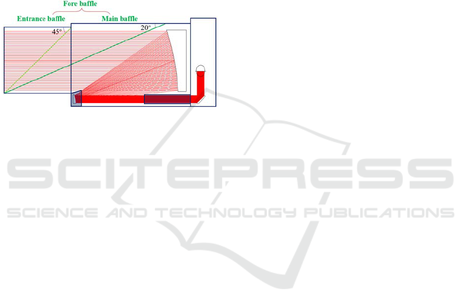
greater than 45 °. A single beam transmission system
is combined into a whole through an outer envelope
primary lens cone between the primary and secondary
mirrors of the system, which is used to reduce the
total weight and the volume of the apparatus. The
entrance baffle and the main baffle form a two-stage
fore baffle which are used to block stray light with an
off-axis Angle greater than 20° outside the field of
view. The baffle vanes are also designed according to
the two-reflect design law, which requires the
incident light to be reflected two times before
reaching the PM.
Figure 4: Two-stage structure layout of the fore baffle.
3.2 Array Design of Inner Baffle
The auxiliary coordinate points needed in the design
of the inner baffle array in the three-aperture off-axis
imaging system are shown in Figure 5. Point O is the
intersection point between the rotational symmetry
axis of the compact off-axis transmission system and
the backplane of the primary mirror, which is set as
the coordinate origin of the whole system. The plane
of the backplane of the primary mirror is the XOY
plane, and the plane perpendicular to the backplate of
the primary mirror points to the incident direction of
the beam is Z-axis direction. Based on this, the right-
handed coordinate system is established. 𝑂
、𝑂
、
𝑂
is the intersection of the optical axis of the off-axis
transmission system of each sub aperture and the
primary mirror backplane, and is also the center
origin of the cylindrical inner baffle of the off-axis
beam combining system of each sub aperture.
According to the relative position of the off-axis
transmission system, its spatial coordinate
is 𝑂
𝑥
,𝑦
,0
;𝑂
𝑥
,𝑦
,0
;𝑂
𝑥
,𝑦
,0
. The
three points A, B and C are respectively the lowest
point of the oblique section edge of the inner baffle in
each sub-aperture off-axis beam transmission system,
which is determined by the optical structure of the
off-axis beam system, and their spatial position
coordinates are A
𝑥
,𝑦
,𝑧
;B
𝑥
,𝑦
,𝑧
;
C
𝑥
,𝑦
,𝑧
. D, E and F are the edge points of the
entrance baffle of the off-axis beam transmission
system of each sub-aperture, which are determined by
the optical structure and system size of the off-axis
beam transmission system, and their spatial position
coordinates are D
𝑥
,𝑦
,𝑧
;E
𝑥
,𝑦
,𝑧
;
F𝑥
,𝑦
,𝑧
. Three points G, H and I are respectively
the highest points of the oblique section edge of the
inner baffle in the off-axis beam transmission system
of each sub-aperture, and their spatial position
coordinates can be obtained by the design method of
the inner baffle array of the compact off-axis beam
transmission system. Figure 6 shows the meridional
profile of a single sub-aperture off-axis beam
transmission system, from which the position of the
central origin 𝑂
of the cylindrical inner baffle of the
sub-aperture off-axis beam transmission system can
be defined. The position of the lowest point A at the
edge of the oblique section of the baffle in the sub-
aperture off-axis beam transmission system; The
position of edge point D of the entrance baffle of the
sub-aperture off-axis beam transmission system; And
the position of the highest point G of the oblique
section edge of the inner baffle of the sub-aperture
off-axis beam transmission system can be
successively determined.
The spatial position coordinates of three points G,
H and I at the aperture edge of the inner baffle of the
off-axis beam transmission system of each sub-
aperture are solved as follows:
a. Solve the plane normal vector by using the basic
method of space vector operation:
𝐴
𝐵
⃗
=
𝑥
−𝑥
,𝑦
−𝑦
,𝑧
−𝑧
=
𝑎
,𝑏
,𝑐
(1
)
𝐴
𝐹
⃗
=𝑥
−𝑥
,𝑦
−𝑦
,𝑧
−𝑧
=
𝑎
,𝑏
,𝑐
(2
)
𝑛
⃗
=
𝐴
𝐵
⃗
𝐴
𝐹
⃗
=
𝑏
𝑐
−𝑏
𝑐
,𝑐
𝑎
−𝑎
𝑐
,𝑎
𝑏
−𝑎
𝑏
=
𝐴
,𝐵
,𝐶
(3
)
In the above equation, 𝑛
⃗
is the normal vector of
the plane determined by three points of ABF.
Similarly, the normal vector of the plane determined
by three points of ACF is 𝑛
⃗
=
𝐴
,𝐵
,𝐶
, and the
normal vector of the plane determined by three points
of BCD is 𝑛
⃗
=
𝐴
,𝐵
,𝐶
.
Furthermore, using the basic method of spatial
analytic geometry, the following plane equation is
obtained:
The plane equation determined by the three points
of ABF is:
PHOTOPTICS 2023 - 11th International Conference on Photonics, Optics and Laser Technology
54

𝐴
𝑥−𝑥
+𝐵
𝑦−𝑦
+𝐶
𝑧−𝑧
=0
(4)
The plane equation determined by the three points of
ACE is:
𝐴
𝑥−𝑥
+𝐵
𝑦−𝑦
+𝐶
𝑧−𝑧
=0
(5)
The plane equation determined by the three points of
BCD is:
𝐴
𝑥−𝑥
+𝐵
𝑦−𝑦
+𝐶
𝑧−𝑧
=0
(6)
b. According to the known coordinate positions of
space points, the following surface equations are
obtained by using the basic method of spatial analytic
geometry:
The equation of cylindrical surface of the inner
baffle of the sub-aperture off-axis beam transmission
system with 𝑂
as the central origin is:
𝑥−𝑥
+
𝑦−𝑦
=
𝑥
−𝑥
+
𝑦
−𝑦
=𝑅
(7)
In the above equation, 𝑅
is the radius of the
cylindrical inner baffle of the sub-aperture off-axis
beam transmission system with 𝑂
as the center of the
circle.
In the same way, the equation of cylindrical
surface of the inner baffle of the sub-aperture off-axis
beam transmission system with 𝑂
as the central
origin is:
𝑥−𝑥
2
2
+ 𝑦−𝑦
2
2
=
𝑥
−𝑥
+
𝑦
−𝑦
=𝑅
(8)
In the above equation, 𝑅
is the radius of the
cylindrical inner baffle of the sub-aperture off-axis
beam transmission system with 𝑂
as the center of
the circle.
The equation of cylindrical surface of the inner baffle
of the sub-aperture off-axis beam transmission
system with 𝑂
as the central origin is:
𝑥−𝑥
+
𝑦−𝑦
=
𝑥
−𝑥
+
𝑦
−𝑦
=𝑅
(9)
In the above equation, 𝑅
is the radius of the
cylindrical inner baffle of the sub-aperture off-axis
beam transmission system with 𝑂
as the center of
the circle.
c. The intersection line is obtained by intersecting the
pairwise plane. The intersection line intersects the
cylindrical surface of a single sub-aperture off-axis
beam transmission system to obtain the spatial
position coordinates of the highest point and lowest
point of the oblique section edge of the inner baffle in
the sub-aperture off-axis beam transmission system.
The lowest point A
𝑥
,𝑦
,𝑧
and the highest
point G𝑥
,𝑦
,𝑧
at the edge of the cylindrical inner
shading tube of the sub-aperture off-axis beam system
with 𝑂
as the center origin are obtained by solving
equations (1), (2) and (4).
The lowest point B
𝑥
,𝑦
,𝑧
and the highest
point H
𝑥
,𝑦
,𝑧
at the edge of the cylindrical inner
shading tube of the sub-aperture off-axis beam system
with 𝑂
as the center origin are obtained by solving
equations (1), (3) and (5).
The lowest point C
𝑥
,𝑦
,𝑧
and the highest
point I
𝑥
,𝑦
,𝑧
at the edge of the cylindrical inner
shading tube of the sub-aperture off-axis beam system
with 𝑂
as the center origin are obtained by solving
equations (2), (3) and (6).
d. After obtaining the highest point and lowest
point of the cylindrical surface edge of the inner
baffle in the off-axis beam transmission system with
a single sub-aperture, the inclination Angle θ of the
oblique section of the inner baffle of the off-axis
beam transmission system is solved according to the
basic method of space vector calculation.
As shown in Figure 7, one end of the inner baffle
of a single sub-aperture off-axis beam transmission
system is plane and fixed on the backplane of the off-
axis primary mirror. The other end is inclined section,
which angle with the normal unit vector 𝑁
⃗
=
0,0,1
of the backplane of the primary mirror is θ.
𝐴𝐺
⃗
=𝑥
−𝑥
,𝑦
−𝑦
,𝑧
−𝑧
is the vector in
the oblique section plane of the cylindrical inner
baffle of the off-axis beam transmission system of the
sub-aperture which central origin is 𝑂
, then the
inclined angle of the inclined section,
θ
=arccos
𝐴
𝐺
⃗
·𝑁
⃗
𝐴
𝐺
⃗
·
𝑁
⃗
(10)
𝐵𝐻
⃗
=
𝑥
−𝑥
,𝑦
−𝑦
,𝑧
−𝑧
is the vector in
the oblique section plane of the cylindrical inner
baffle of the off-axis beam transmission system of the
sub-aperture which central origin is 𝑂
, then the
inclined angle of the inclined section,
θ
= arccos
𝐵𝐻
⃗
·𝑁
⃗
𝐵𝐻
⃗
·𝑁
⃗
(11)
𝐶𝐼
⃗
=
𝑥
−𝑥
,𝑦
−𝑦
,𝑧
−𝑧
is the vector in the
oblique section plane of the cylindrical inner baffle of
the off-axis beam transmission system of the sub-
Design of Inner Baffle Array for Compact Multi-Aperture Off-Axis Optical System
55
aperture which central origin is 𝑂
, then the inclined
angle of the inclined section,
θ
= arccos
𝐶𝐼
⃗
·𝑁
⃗
𝐶𝐼
⃗
·
𝑁
⃗
(12)
e. In the multi-aperture off-axis beam transmission
system, the inclined section of the inner baffle which
center is 𝑂
is perpendicular to the plane determined
at three points AG𝑂
. And the angle between it and
the normal vector 𝑁
⃑
of the backplane of primary
mirror is θ
.
In the multi-aperture off-axis beam transmission
system, the inclined section of the inner baffle which
center is 𝑂
is perpendicular to the plane determined
at three points 𝐵𝐻𝑂
. And the angle between it and
the normal vector 𝑁
⃑
of the backplane of primary
mirror is θ
.
In the multi-aperture off-axis beam transmission
system, the inclined section of the inner baffle which
center is 𝑂
is perpendicular to the plane determined
at three points𝐶𝐼𝑂
. And the angle between it and the
normal vector 𝑁
⃑
of the backplane of primary mirror
is θ
.
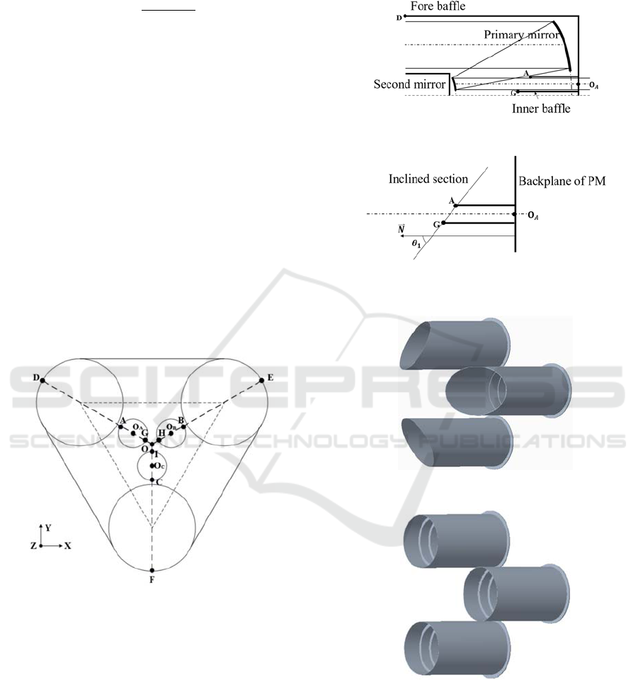
Figure 5: Key point indicator diagram.
In the 3D modeling software, according to the
above spatial position relationship and the angle θ
、
θ
、
θ
of the inclined section calculated in Step 4,
the inner baffle array of the compact multi-aperture
off-axis beam transmission system can be easily and
quickly established. The inner baffle array of the
compact three-aperture off-axis beam transmission
system is shown in Figure 8. Compared with the
three-aperture off-axis beam transmission system
with flat port as shown in Figure 9, the oblique
structure of the inner baffle array is more reasonable.
Under the condition of not blocking the imaging light
of the system, the shading range of the inner baffle
array to stray light outside the view field is fully
increased.
Figure 6: Auxiliary coordinate point indication diagram.
Figure 7: Meridional profile of a single sub-aperture off-
axis beam transmission system.
Figure 8: Inclined section inner baffle array.
Figure 9: Flush inner baffle array.
4 BLACK BAFFLE SURFACE
MEASUREMENT
Optical instruments and telescopes rely on black
baffle and vane surfaces to minimize the effect of
PHOTOPTICS 2023 - 11th International Conference on Photonics, Optics and Laser Technology
56
stray light on overall system performance. For well-
designed and well-baffled systems, the black surfaces
chosen for the baffles and vanes can play a significant
role in reducing the stray light on the detector. Space-
based surfaces must withstand severe launch
vibrations, temperature extremes, collisions with
space debris and micrometeoroids, and exposure to
ultraviolet radiation.
Taking into account the environmental
adaptability and structural rigidity of the baffle, we
measured the surface scattering characteristics of
samples of four materials: inorganic anodized Al/SiC,
anodized TC4, and untreated CFRP, anodized invar
steel. Modular Light Scattering System (MLS 5) was
used as the test equipment, as shown in Figure 10.
Laser has high brightness, good directivity and high
stability, which makes it a conventional light source
for optical scattering measurements. The laser
illuminates the sample surface to generate scattered
light, and the detector with pinhole solid angle
receives the scattered light energy of different
scattering angles. The scattering measurement curves
of the four sample surfaces are shown in Figure 11.
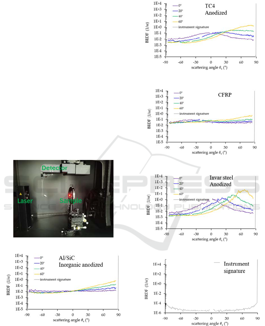
Figure 10: The BRDF measurement scene.
(a)
(b)
(c)
(d)
(e)
Figure 11: Measured BRDF data for sample (a) Al/SiC
inorganic anodized (b) TC 4 anodized (c) CFRP (d) Invar
steel anodized (e) instrument signature for a scan along to
the plane of incidence.
Design of Inner Baffle Array for Compact Multi-Aperture Off-Axis Optical System
57

According to the measured data, it can be seen that
the BRDF of inorganic anodized Al/SiC and
untreated CFRP is small, followed by anodized TC4
and anodized invar steel is the largest. Considering
the processing performance and cost performance of
the materials, etc., finally, CFRP was selected as the
baffle material for the compact multi-aperture
imaging instrument.
5 SIMULATION ANALYSIS
The measured CFRP surface scattering data are
brought into the surface property editor module of
Tracepro, a stray light analysis software. The
measured surface property is assigned to the mask
model. The off-axis angle range of the stray light is
18°-28°, where the out of field stray light incident
from the adjacent aperture can directly through the
back plate of the primary mirror, and shine on the 45
°mirror. We analyzed the PST of the system within
this off-axis angle range, and the curve obtained by
simulation analysis is shown in Figure 12. The red
curve in the Figure shows the PST data of the model
simulation with the inclined section inner baffle
array. The blue curve in the Figure shows the PST
data of the model simulation with the flush section
inner baffle array. It can be seen from the curve in the
Figure that although the PST values of model with the
in inclined section inner baffle array have some
fluctuations, they are all three orders of magnitude
smaller. It can be explained that the proposed method
can effectively improve the cross-talk of external
stray light between the sub-aperture of the multi-
aperture off-axis beam transmission system.
Figure 12: PST value between 18° and 28° off-axis angle.
6 CONCLUSION
In this paper, a fast modeling method is designed for
a compact multi-aperture off-axis imaging system,
and an opto-mechanical model equipped with a two-
stage fore baffle and an inner baffle array is designed
by taking the compact three-aperture off-axis imaging
system as an example. The BRDF data of anodized
Al/SiC, anodized TC4, untreated CFRP and anodized
invar steel were tested by scatterometer. Finally
choose untreated CFRP with the highest cost
performance as the material of the baffle. The surface
attribute editing function in the stray light analysis
software was used to bring the actual measured
BRDF data into the opto-mechanical model, and the
PST of the inclined section and the flush section of
the inner baffle array were simulated and calculated
respectively. The analysis results show that the
proposed method can effectively improve the cross-
talk of external stray light between the sub-aperture
of the multi-aperture off-axis beam transmission
system.
ACKNOWLEDGEMENTS
J. L. Guo, M. L. Zhang, thanks for providing
mechanical structure models for the analyses.
REFERENCES
E. C. Fest, (2013) Stray Light Analysis and Control, SPIE
Press, Bellingham, Washington .
M. Asadnezhad, A. Eslamimajd, H. Hajghassem, H.
Hajghassem. (2018) Stray light analysis, baffle, and
optical design of a high-resolution satellite camera. J.
Appl. Remote Sens. 12, 026009.
C. Leinert, D. Kluppelberg. (1974) Stray light suppression
in optical space experiments. Appl. Opt., 13, 556-564 .
W. L. Hales. (1992) Optimum Cassegrain baffle systems,
Appl. Opt. 31, 5341–5344 .
M. S. Kumar, C. Narayanamurthy, and A. K. Kumar. (2013)
Iterative method of baffle design for modified Ritchey-
Chretien telescope, Appl. Opt. 52, 1240–1247 .
S. M. Pompea and R. P. Breault. (1995) Black surfaces for
optical systems, in Handbook of Optics, M. Bass, Ed.,
2nd ed., 2, 37.31-37.63 (1995).
Peixian Han, JunliGuo. (2021) Optical design and stray
light control for the space-based laser space debris
removal mission, Appl. Opt. 2021,60(25):7721-7730.
PHOTOPTICS 2023 - 11th International Conference on Photonics, Optics and Laser Technology
58
