
Hierarchical Design of Cyber-Physical Systems
Daniela Genius
1
and Ludovic Apvrille
2
1
Sorbonne Université, LIP6, CNRS UMR 7606, Paris, France
2
LTCI, Télécom, Institut Polytechnique de Paris, Sophia-Antipolis, France
Keywords:
Cyber Physical Systems, Analog/Mixed Signal Design, SystemC AMS, Virtual Prototyping
Abstract:
Cyber-physical systems are based upon analog / digital hardware and software components. The splitting into
functionalities and interaction between analog and digital parts should be considered as early as possible in the
design phase, relying on formal verification or simulation. While many papers pretend to propose a modeling
environment supporting them, only a few of them really address the different Models of Computation of these
systems because they strongly differ. The paper explains how to generate a combined SystemC/SystemC AMS
virtual prototype of the analog and mixed-signal parts of CPS directly from a SysML model featuring whole
parts of CPS, thus reconciling near-circuit precision with more abstract analog and digital models.
1 INTRODUCTION
Cyber-physical systems (CPS) span three domains:
analog, digital and physical, using most often off-the-
shelf analog and digital components for their design.
Yet, when special requirements have to be met (such
as: low-power, very small size, specific application,
etc.) such off-the-shelf components may be too costly
or unavailable, advocating for from-scratch designs,
sometimes both for analog and digital parts.
For such custom designs, the splitting of function-
alities between analog and digital parts, and their in-
teraction, is of prime importance, and should there-
fore be done as early as possible. In early design
phases, simulation or formal verification helps taking
decisions. But, in the case of mixed signal design,
i.e., designs with analog and digital parts, the Models
of Computation (MoC) of these two aspects strongly
differ: they are commonly designed at different ab-
straction levels, depending on the design patterns al-
ready available. Last, due to the significant semantic
difference between MoCs, similar models or unique
tools can not be used to study the same system.
TTool (Apvrille, ), an open-source modeling and
verification framework, provides to some extend
analog/mixed signal modeling and virtual prototyp-
ing. It offers a multi-level virtual prototyping and
simulation environment that can be executed from
SysML models, featuring all necessary elements to
capture analog and digital aspects. Analog / mixed-
signal parts of the virtual prototype are generated in
the SystemC AMS language (Vachoux et al., 2003).
Our previous contributions (Genius et al., 2019)
already highlighted how to jointly express in SysML
analog and digital parts, and how our tool can support
this. Based on these, the present paper explains how
to efficiently capture analog parts of CPS that require
more detailed modeling in a third MoC – as well as
the interactions between the three MoCs – and how to
generate a SystemC AMS virtual prototype directly
from these new SysML models. Abstraction levels
thus now range from a near-circuit precision up to
more abstract analog and digital models (e.g., trans-
actional models). Just like many SysML tools, TTool
already offers verification capabilities for the digital
parts, thus this part is not addressed in the paper.
Related work is discussed in Section 2,basic con-
cepts of SystemC AMS modelling are introduced in
Section 3. Section 4 describes our contribution (mod-
eling and simulation). Section 5 shows a complex
case study, a scalable analog-to-digital converter.
2 RELATED WORK
The contribution of the paper is at the intersection be-
tween two research domains: model-based design for
cyber-physical systems and analog/mixed signal hard-
ware design.
UML/SysML based modeling techniques have
been employed to model cyber-physical systems
(Selic and Gérard, 2013). With few exceptions, how-
ever they do not support refinement until a low level
of abstraction.
Ptolemy, perhaps the most well known and ini-
tially based on a data-flow model, evolved into
Genius, D. and Apvrille, L.
Hierarchical Design of Cyber-Physical Systems.
DOI: 10.5220/0011654400003402
In Proceedings of the 11th International Conference on Model-Based Software and Systems Engineering (MODELSWARD 2023), pages 117-124
ISBN: 978-989-758-633-0; ISSN: 2184-4348
Copyright
c
2023 by SCITEPRESS – Science and Technology Publications, Lda. Under CC license (CC BY-NC-ND 4.0)
117

Ptolemy II (Ptolemy.org, 2014), which proposes
many different MoCs including continuous time, data
flow and DE and studies their heterogeneous combi-
nations; MoCs can be combined hierarchically.
Metro II (Davare et al., 2007) is based on hier-
archical high level models. A common simulation
kernel handles the entire execution, leaving the im-
plementation of synchronization mechanisms to the
designer.
Modelica (Fritzson and Engelson, 1998), an
object-oriented modeling language for describing and
simulating cyber-physical systems, comes without
predefined time synchronization.
Linking simulations with different Models of
Computation can also be done by using the Functional
Mock-up Interface (Blochwitz et al., 2011), which is
closely related to the Modelica tools.
Into-CPS (Fitzgerald et al., 2013) uses model-
based formal methods by integrating discrete-event
models of controllers with continuous-time models of
their environments.
The SICYPHOS framework (Wawrzik et al.,
2015) proposes SysML for the overall model of the
system structure and component interfaces between
domains, which are then translated into domain-
specific languages like SystemC AMS or Modelica.
3 SystemC-AMS MODELING
SystemC AMS (Accellera Systems Initiative, 2010) is
an extension of SystemC with AMS (Analog/Mixed
Signal) and RF (Radio Frequency) features (Vachoux
et al., 2003); several MoC are predefined. The in-
dustrial framework COSIDE (Einwich, 2022) handles
validation of hardware against software and gener-
ates Simulink or C Code. Digital components are de-
scribed by a Discrete Event (DE) MoC, while analog
components follow the Timed Data Flow (TDF) MoC,
based on the timeless Synchronous Data Flow seman-
tics (Lee and Messerschmitt, 1987). The most low-
level MoC is called Electrical Linear Network (ELN).
It relies on equations to capture the behavior of elec-
trical circuits in a simplified way.
3.1 Discrete Event
A DE simulation abstracts a system as a discrete se-
quence of events in time, where each event signals a
change of state, in contrast to continuous simulation
in which the system state changes continuously over
time. SystemC AMS DE modules have input and out-
put ports, and contain SystemC code.
3.2 Timed Data Flow
A TDF module samples continuous functions at dis-
crete intervals. Such a module is described with an
attribute representing the time step and a processing
function, a mathematical function depending on the
module inputs and/or internal states.
TDF modules have the following attributes:
1. Module time step (Tm) denotes the period during
which the module is activated, which is the case if
enough samples are available at its input ports.
2. Rate (R). Each module reads or writes a fixed
number of data samples each time it is activated,
annotated to the port as port rate.
3. Port time step (Tp) denotes the time interval be-
tween two operations (read or write).
4. Delay (D). A delay can be assigned to a port and
will make the port read or write samples only in
the following activation of the port.
At each time step, a TDF module reads a fixed
number of samples from its input ports, executes the
processing function, and writes a fixed number of
samples to its output ports. Schedulability denotes
the correct static execution order of TDF modules
in a cluster containing several modules; a cluster is
schedulable if the module time step is consistent with
the rate and time step of any port within a module.
3.3 Electrical Linear Networks
The ELN model of computation introduces the use
of electrical primitives and their interconnections to
model conservative, continuous-time behavior. The
ELN modeling style allows the instantiation of elec-
trical primitives, connected by electrical nodes. The
mathematical relations between the primitives are de-
fined at each node in the network, where both the po-
tential (voltage) and flow (current) quantities are used
according to Kirchhoff’s laws. The electrical network
is represented by a set of differential algebraic equa-
tions that are taken into account at simulation.
SystemC AMS extensions offers a limited set of
primitive modules; unlike for TDF models, there is no
possibility to implement user-defined electrical prim-
itives. An ELN module gives a detailed representa-
tion of an electrical circuit. Yet, non-linear behavior
cannot be represented; as a consequence, nonlinear
elements such as diodes and transistors must be ap-
proximated with the existing linear components.
MODELSWARD 2023 - 11th International Conference on Model-Based Software and Systems Engineering
118
Software
design
Deployment
Hardware
design
Digital
hardware
model
Analog
hardware
model (ELN)
Analog
hardware
model (TDF)
Virtual prototype
HW/SW partitioning
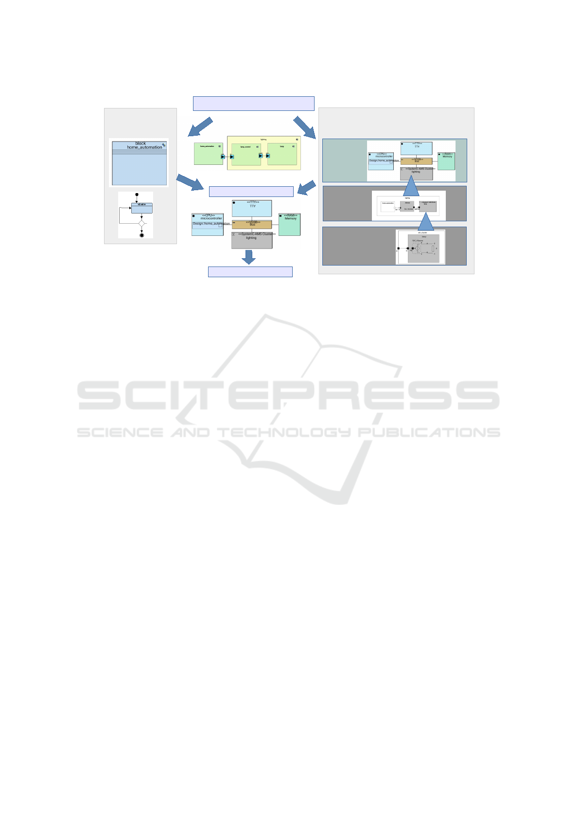
Figure 1: Overview of the hierarchical Method with software design.
3.4 Simulating the MoC
Converter ports are required to connect DE compo-
nents to TDF components, and reciprocally. Con-
verter modules can connect ELN components to TDF
or DE modules. When connecting such components,
the timing and consistency issues between their dif-
ferent MoC, in particular between TDF and DE, are
delicate to handle (Cortés Porto et al., 2021; Andrade
et al., 2015). For ELN modules, a time step can be
directly assigned to modules or propagated using the
mechanism of the time step within an ELN equation
system. In case an ELN model is connected to a TDF
model, the time steps from the connected TDF ports
are propagated to the ELN model.
4 HIERARCHICAL MODELING
OF ANALOG HARDWARE
COMPONENTS
In the following, we highlight our new contribution:
the integration of the ELN MoC. The TDF model
of computation (higher abstraction level) is often in-
sufficient to deal with highly specialized custom cir-
cuits (Accellera Systems Initiative, 2010). In par-
ticular, precise interactions with the environment are
expected to be studied as soon as possible, before
the actual design is complete: this can be done with
TDF descriptions only. We present in the following
a top-down, hierarchical manner, using a customized
SysML meta-model and generating code to be used in
a SystemC/SystemC AMS simulation environment.
In simulation environments for SystemC-AMS in-
tegrating TDF and DE MoC, the simulation of DE
components there controls the TDF simulation. In-
spired by this simulation hierarchy, we propose a
three-level modeling –between which a designer can
navigate back and forth– using three kinds of di-
agrams representing analog/mixed signal hardware,
where the DE simulator controls the TDF simulator,
which in turn controls the ELN simulation.
4.1 Method Overview
Figure 1 displays the overall design method which
we suggest for systems with digital and analog parts.
The top of the figure focuses on the hardware/soft-
ware partitioning step: a functional representation is
mapped onto a hardware platform, like in (Apvrille,
). This mapping concerns both functions (mapped to
e.g. processors or hardware accelerators) and commu-
nications (mapped to buses, bridges, memories, . . . ).
Once the functionality has been partitioned into soft-
ware tasks (represented on the left) and hardware, the
deployment diagram (top right) represents all of the
selected hardware.
The "Hardware Design" part is the main contribu-
tion of this paper. The top part on the right of Figure
1 captures an analog/mixed signal cluster as a grey
box in the bottom of the "Digital Hardware Model".
The other nodes correspond to the digital parts of the
Virtual Prototype. The middle part ("Analog hard-
ware model (TDF)") zooms into this grey box (it can
be opened with a double-click). It shows the SysML
representation of the TDF model of this cluster. The
three modules of this level capture, from left to right,
an output to the digital domain, a TDF block and
an abstract representation of an ELN module. Last,
the lower hierarchical level ("Analog hardware model
(ELN)") is destined for detailing ELN modules.
Hierarchical Design of Cyber-Physical Systems
119
Once software and (digital and analog) hardware
have been designed, a virtual prototype can be gen-
erated. This prototype is built from a free SystemC
library, and from analog hardware components de-
scribed in SystemC AMS, some of these components
being detailed in ELN.
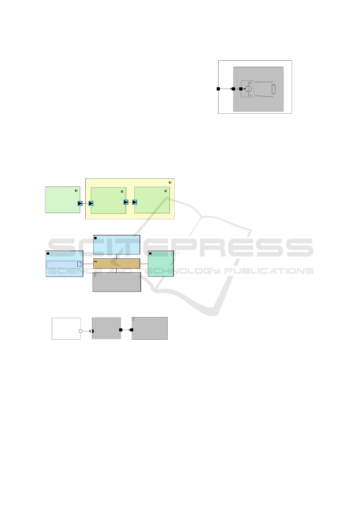
4.2 Modeling DE-TDF-ELN Modules
Figure 2 displays SysML blocks used to describe a
small home automation/lighting system, composed of
a light bulb supplied with a voltage controlled by a
dimmer, which in turn is controlled by the software
running on the —digital–microcontroller of a home
automation system. Figures 3 to 5 show the digital,
TDF and ELN hardware views, respectively.
lighting
lamp
in2
lamp_control
out2
in
home_automation
out
lighting
lamp
in2
dimmer
out2
in
Figure 2: Functional model of the lighting system.
<<CPU>>
CPU
Design::application_code
<<RAM>>
Memory
<<VGSB>>
Bus
<<SystemC-AMS Cluster>>
my_tdf_cluster
<<TTY>>
TTY
<<CPU>>
microcontroller
Design::home_automation
<<RAM>>
Memory
<<VGSB>>
Bus
<<SystemC-AMS Cluster>>
lighting
<<TTY>>
TTY
Figure 3: Deployment Diagram.
my_tdf_cluster
DE_block
outout
<<SystemC-AMS ELN>>
my_eln_cluster
inin
tdf_block
Tm = 1.0 ms
inin
outout
lighting
home_automation
outout
<<SystemC-AMS ELN>>
lamp
inin2
dimmer
Tm = 10.0 ms
inin
outout2
Figure 4: Representation combining three different MoC.
Digital hardware, with possibly software running
on it, is represented in a UML Deployment Diagram
(see Figure 3: A microcontroller (CPU) and its soft-
ware application are shown in the light blue box on
the left (named CPU and application_code, respec-
tively). The platform also features a bus, a RAM
memory and a TTY for monitoring and debugging.
TDF clusters are represented in the deployment dia-
gram as grey boxes; in Figure 3, the TDF controller
is shown as a grey box on the bottom. The DE block
shown in the left of Figure 4 represents the interface
to the microcontroller.
eln_cluster
lamp
in
TDF_VSource
p
n
inp
R
p
n
a
b
in
eln_cluster
in
lamp
in
TDF_VSource
p
n
inp
R
p
n
a
b
Figure 5: TDF cluster encapsulating an ELN diagram.
By selecting such a TDF cluster (here: lighting),
the user opens a panel like the one shown in Figure
4. The left part of this Figure, home_automation, rep-
resents the interface to the digital hardware, for ex-
ample a micro controller or general purpose platform
running application code. This block is connected to
a TDF block (in the middle) which samples the in-
put on the converter port at a given frequency (indi-
cated by T _m = 10.0ms in the TDF block dimmer).
Causality issues between the TDF and the DE MoC
are explained in (Cortés Porto et al., 2021).
The right hand side of the Figure shows the en-
capsulation of a ELN cluster (lamp) into a TDF clus-
ter (lighting). Input and output are handled via TDF
ports, for which the sampling frequency of 10 ms
is imposed. The main idea is that an ELN mod-
ule –like for instance lamp in Figure 5– is repre-
sented in the TDF panel, featuring the appropriate
TDF ports. However, the precise handling of inputs
and outputs by ELN components is hidden at this ab-
straction level: it will be supplied later.
By selecting the ELN cluster block, the user opens
the corresponding ELN panel (Figure 5). In this toy
example, the left hand module has a TDF input port
connected to a TDF-to-ELN converter module, a TDF
controlled voltage source TDF_VSource. This mod-
ule is in turn connected via its positive (p) and neg-
ative (n) terminals to an ELN resistor. Currently, we
support 20 elements out of the 29 defined in the Sys-
temC AMS standard, not counting ports, connectors
and terminals.
Figure 6 shows the toolbar of TTool’s new ELN
panel featuring all graphical operators which are sup-
ported: voltage or current sources, linear lumped ele-
ments (resistors, capacitors, inductors), transmission
lines, ideal transformers and amplifiers, and ideal
switches, each with either TDF or DE ports.
4.3 Virtual Prototype Generation
For a virtual prototype containing three different
Models of Computation, it is particularly important
that interactions between the MoC are handled as
early as possible in the design process. (Cortés Porto
MODELSWARD 2023 - 11th International Conference on Model-Based Software and Systems Engineering
120
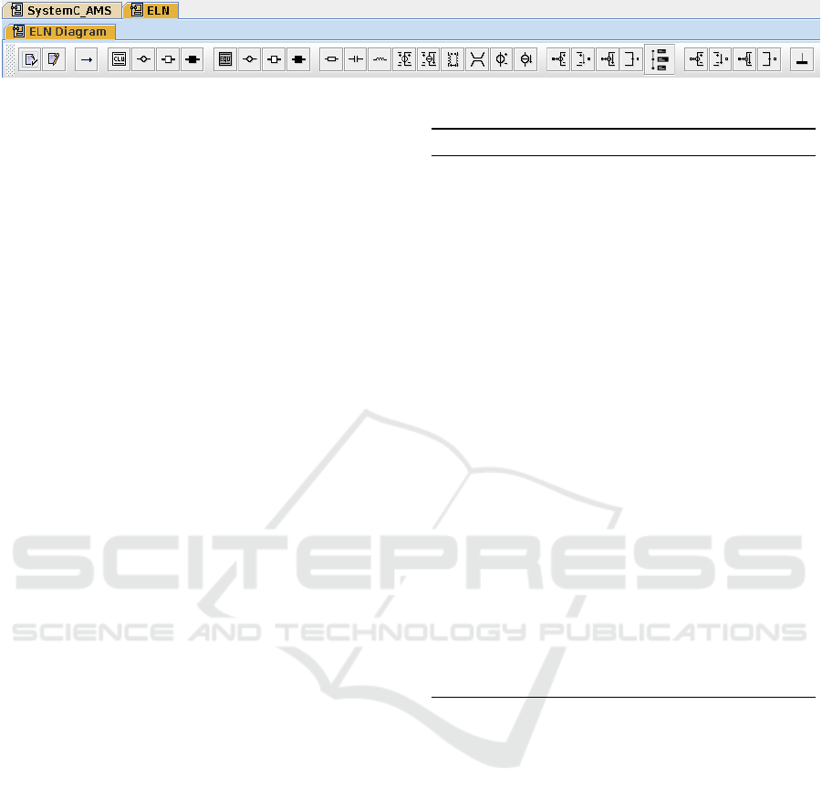
Figure 6: ELN Panel Toolbar.
et al., 2021) has already shown how to efficiently gen-
erate TDF and DE parts of the prototype as well as
their interaction. In TTool, this can be done as fol-
lows:
1. Select one of the TDF clusters, including the ones
with ELN clusters.
2. Activate the "Validation" button. This checks for
coherency of the time steps within the TDF clus-
ter as well as for respect of temporal causality be-
tween TDF and DE models.
3. Activate "Code generation" button. This gener-
ates, for all ELN clusters, SystemC AMS TDF
module templates with the appropriate input and
output ports, leaving processing functions empty.
4. Select one of the ELN clusters in the TDF cluster.
5. Activate the "Code generation" button. This gen-
erates, for the selected ELN cluster representa-
tion, SystemC AMS code for the ELN module it-
self and updates the template for the surrounding
TDF block with the instantiation of the internal
ELN blocks and the signals connected to the in-
ternal ports.
In our tool, the design choice was made that ELN
clusters are always modeled inside TDF blocks. Our
algorithm (Cortés Porto et al., 2021) propagates the
time steps and checks schedulability and causality on
the abstraction level level where interaction between
TDF/DE blocks is analyzed. An ELN cluster thus can
never be simulated alone, it requires a TDF block that
forces its time step.
Code has also to be generated for:
• The top cell, containing the simulation entry
point, TDF and DE block instantiation, code for
starting and stopping the simulation and optional
code for tracing.
• The ELN cluster encapsulation module. This is a
TDF module instantiating the ELN modules, their
connections among each other and to the TDF
modules.
• The ELN module itself.
Listing 1 shows the transformation for code genera-
tion and scheduling, leaving out the DE part and using
the scheduling algorithm CALCULATESCHEDULE of
(Cortés Porto et al., 2021) for TDF clusters.
Listing 1: Code generation and scheduling algorithm.
1: procedure GENERATESYSTEMCAMSCODE
▷ T time step, B block,
▷ C cluster, M module
2: for each TDF cluster C
TDF
do
3: generate cluster code
4: for all TDF blocks B
TDF
in C
TDF
do
5: CALCULATESCHEDULE (C
TDF
)
6: if B
TDF
simple TDF block then
7: generate TDF block code
8: else
▷ B
TDF
contains ELN cluster C
ELN
9: for all M
ELN
∈ C
ELN
do
10: set T
M
ELN
from B
TDF
11: determine T
pi
, T
po
for B
TDF
12: end for
13: calculate T
C
ELN
14: CALCULATESCHEDULE (C
TDF
)
15: if C
TDF
schedulable then
16: generate encapsulation code
17: for all M
ELN
∈ C
ELN
do
18: generate ELN code
19: end for
20: end if
21: end if
22: end for
23: end for
24: end procedure
4.4 Virtual Prototype
Our simulation environment applies the following hy-
potheses:
• The behavior of ELN modules can be described
with mathematical equations: these equation sys-
tems are solved numerically by the simulation en-
gine at appropriate time steps. Also, for ELN
modules connected to a TDF module, the time
step from the connected TDF port(s) is propagated
to the ELN module. Consistency between locally
defined ELN module time steps and propagated
time steps is checked by SystemC AMS.
• In the presence of DE modules, the DE simula-
tor controls the entire simulation via the converter
ports, respecting temporal causality.
• TDF modules impose their timestep on the ELN
modules, as described in (Accellera Systems Ini-
tiative, 2010).
Hierarchical Design of Cyber-Physical Systems
121
• Even if possible according to (Accellera Systems
Initiative, 2010), direct assignment of a timestep
to an ELN module is currently not allowed.
In the simulation, the TDF cluster is analyzed, then
the equations of the ELN cluster solved.
5 CASE STUDY: SCALABLE SAR
ADC
As stated in the introduction, cyber-physical systems
span three domains (analog, digital and physical).
The digital and analog domains are interconnected
with digital-to-analog (DAC) and analog-to digital
(ADC) converters. These converters are expected to
be of small size and designed with high energy ef-
ficiency in mind. Successive Approximation Regis-
ter (SAR) ADCs provide good power efficiency for
medium-resolution applications. ADC should fur-
thermore support multiple applications, so their de-
sign is required to be easily reconfigurable. The basic
idea of SAR ADCs is to approximate the actual volt-
age successively by several iterations, corresponding
to the number of bits which are fed back to a DAC.
The most essential parameter of this circuit is its bit
precision, spanning from 3 to 12-bit.
We consider a SAR ADC designed by our electri-
cal circuits team in a recent common project (Louërat
and Porte, 2022). One interesting challenge was
to obtain a system-level model of the ADC circuit,
which was not yet available at the beginning, in order
to evaluate the interplay of digital (Ctl logic) and ana-
log (Comparator and DAC) circuits. In particular, the
number of bits of precision ultimately required by the
system was not yet known, the corresponding system-
level model thus had to be easily parameterizable. In
the scope of this project, we could thus evaluate the
new extensions our SysML-based modeling tool on a
rather complex use case.
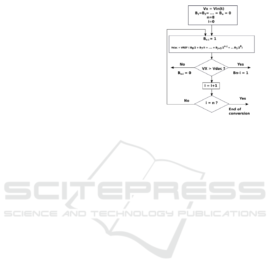
Figure 7 shows the main algorithm of the
ADC (Louërat and Porte, 2022). Basically, an incom-
ing voltage V_x is to be determined iteratively. An
initial voltage value is set to V _in and all bits are set
to 0. Then, the most significant bit (MSB) B
n
is set
to 1. At a given iteration i, V_x is compared to a gen-
erated voltage V _dac. A bit is set to 1 if the voltage
is higher, set to 0 if the voltage is lower, starting with
MSB B
n
and progressing down to B
1
. These bits B
1
to B
n
are used to control a digital analog converter
(DAC), which produces the more precise voltage for
the next iteration.
Figure 7: Conversion algorithm (with permission from
(Louërat and Porte, 2022)).
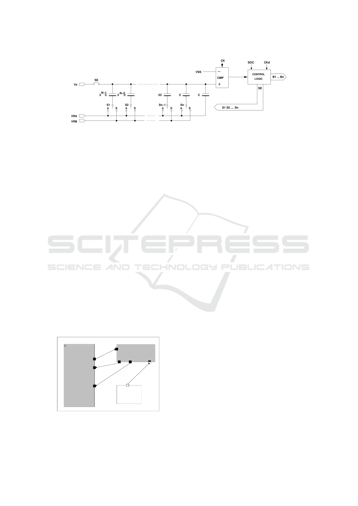
5.1 Models
Figure 8 shows the detailed hardware implementa-
tion proposed by (Louërat and Porte, 2022): a non-
differential ADC with implicit sampling using capac-
itor top plates. On the upper center, we find a com-
parator (CMP) which compares zero/ground voltage
(VSS) to the voltage generated in each cycle by the
DAC (VDAC). Shown on the lower left hand side,
the DAC produces this voltage from i + 1 capacitors
which are either activated (switch closed) when the
control bit S_i is 1, deactivated when it is 0. B_i has
the same value as S_i but is destined for digital out-
put. Thus, during n iterations, the incoming voltage
is approximated with n bit precision. The additional
capacitor on the right sets the starting capacity, the
others then yield 2
0
,2
1
, ... 2
N−1
times that capacity.
The implementation of this design is a challenging
test case for our tool extension, because (i) the digital
control circuit and the analog comparator and DAC
are combined on a single chip and (ii) the complexity
of low level modeling is high.
5.1.1 Digital Hardware Model (DE)
System-level design is restricted to the external dig-
ital control in our study to the generation of a Start-
of-Conversion (SoC) signal generated by software. In
current experimentation, code on the digital platform
is essentially limited to giving start/stop signals, to
I/O and debug functionality. The sampling algorithm
is implemented in the Control Logic component. Des-
tined to be implemented in hardware, it was translated
to SystemC from the VHDL digital hardware descrip-
tion language and precisely reflects the functionality
MODELSWARD 2023 - 11th International Conference on Model-Based Software and Systems Engineering
122
VDAC
Figure 8: Analog-Digital converter: electronic design (simplified, with permission from (Louërat and Porte, 2022)).
shown in the algorithm of Figure 7.
5.1.2 Analog Hardware Model (TDF)
Figure 9 gives an overview of the overall SysML
based representation of the TDF design. On this level,
the entire digital part running the software is repre-
sented on the lower right within one DE block, whose
only role is to provide the start of conversion (SoC)
signal on its output port. The control_logic block fea-
tures TDF and converter ports.
The comparator-and-DAC block has two TDF en-
try ports called start_conversion and in_bits. The
start_conversion TDF signal is received from the con-
trol_logic block, the in_bits signal contains the n bits
controlling the switches in the DAC; the arity of a
TDF port can be configured. The block also features
an output port VDD_out, providing the voltage calcu-
lated after each iteration of the algorithm (output of
CMP block in Figure 8), a floating point value.
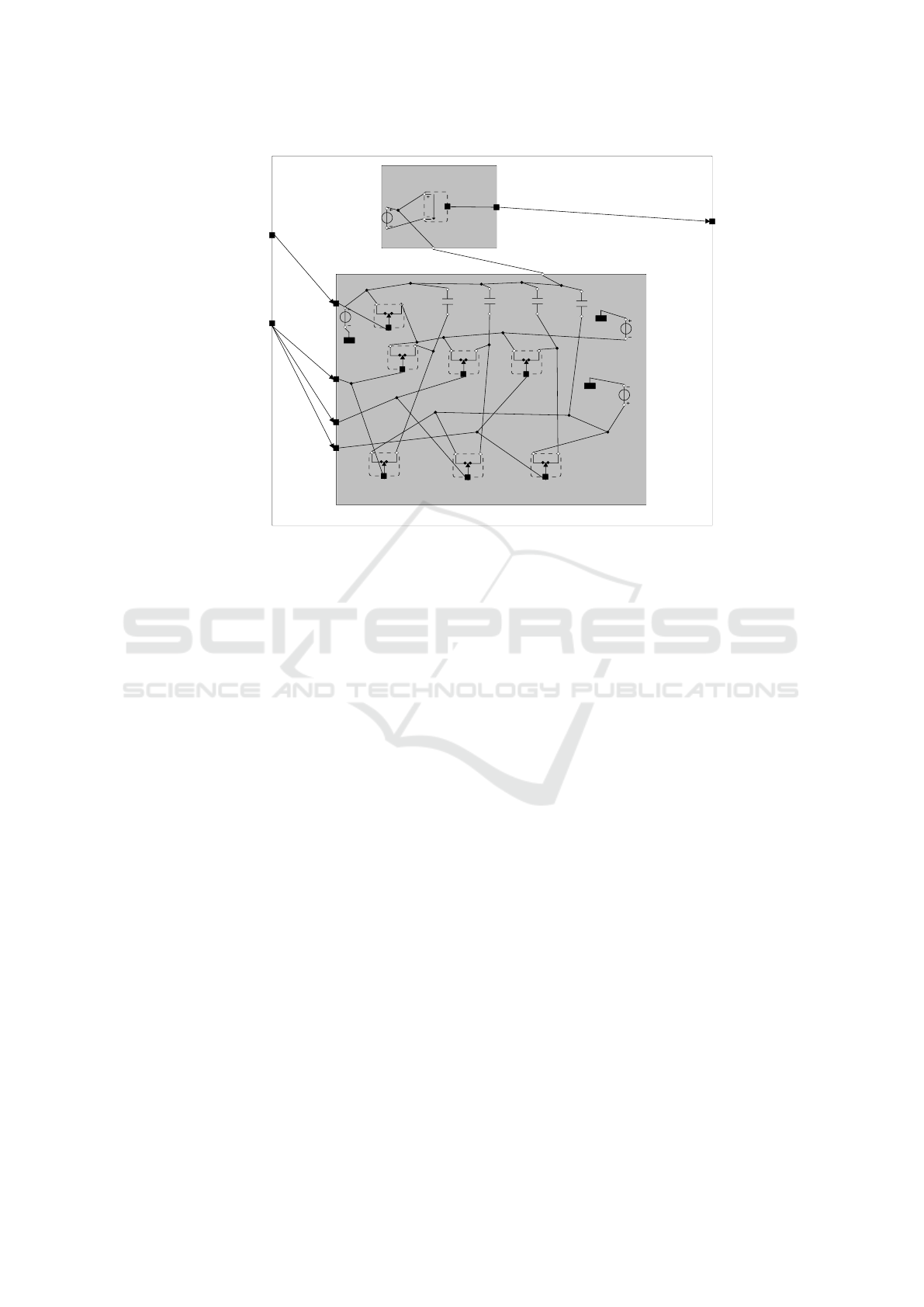
5.1.3 Analog Hardware Model (ELN)
Double clicking on the comparator_and_DAC block
opens the most detailed view (Figure 10). The com-
parator_and_DAC block actuelly contains the two
analog ADC blocks Comparator (CMP) and DAC
(representing the entire left part of Figure 8). These
blocks are described in SystemC AMS ELN.
sar_adc
SoC
<<SystemC-AMS ELN>>
comparator_and_DAC
in_bitsin_bits
VDD_outVDD_out
start_conversionstart_conversion
control_logic
Tm = 1.0 ms
SoC
to_dac
cmp
start_conversion
Figure 9: TDF model view of the SAR-ADC in the tool.
The comparator on the top receives V_dac, on an
ELN terminal (bottom of the block) from the DAC
that produced it with the SAR method. It is compared
to the voltage to be measured, V_x, modeled by an
independent voltage source on the left of the com-
parator. At each iteration, the result of the succes-
sive aproximations is transmitted to the control_logic
block by a TDF port VDD_out (a double value) .
The lower part of the Figure represents the DAC.
The voltage Ve is generated by the independent volt-
age source (upper left). Two rows of three TDF con-
trolled switches take up the central part of the design
and are connected, by their control ports, to one of
three TDF in_bits signals, each representing one of
the control bits for one switch of each row. Of the
four capacitors, three are controlled by two switches
each. C0, not controlled by a switch, imposes the ini-
tial capacitor value which is then doubled, quadrupled
etc. as described in the algorithm above, by activating
more and more switches. A seventh switch is con-
nected to the start_conversion port.
6 CONCLUSION AND FUTURE
WORK
SystemC AMS based hierarchical design of cyber-
physical systems is now possible with our tool, with a
real support for both digital and analog parts. TTool
already provides comfortable possibilities to model,
verify and simulate embedded software on a virtual
prototype; this aspect has been left out in the present
paper in order to focus on the hardware design part.
Currently, the consistency between ELN and TDF
is checked by the SystemC AMS simulator. The hy-
potheses from section 4.4 can be used to validate
schedulability and causality between TDF and ELN
before simulation, at prototyping time.
ELN diagrams can quickly become complex to be
read: we are thus working on visual improvements,
such as the use of colors and a better representation
for line crossing.
Hierarchical Design of Cyber-Physical Systems
123
p n
ctrl
Ve
p
n
gnd
TDF_Switch_b2
n p
ctrl
vdd_out
in_bits
C0
p
n
C1
p
n
C2
p
n
C3
p
n
VRA
n
p
VRB
p
n
TDF_Switch1
n p
ctrl
TDF_Switch2
n p
ctrl
TDF_Switch3
n p
ctrl
in_bits_2
in_bits_1
TDF_Switch_b3
n p
ctrl
TDF_Switch_b1
n p
ctrl
start_conversion
comparator
TDF_VSink0
comparator_and_DAC
in_bits
DAC
gnd
gnd
TDF_Switch0
p n
Ve
p
n
gnd
TDF_Switch_b2
n p
C0
p
n
C1
p
n
C2
p
n
C3
p
n
VRA
n
p
VRB
p
n
TDF_Switch_a1
n p
TDF_Switch_a2
n p
TDF_Switch_a3
n p
TDF_Switch_b3
n p
TDF_Switch_b1
n p
comparator
TDF_VSink0
p
n
VDD_out
V_in
p
n
start_conversion
V_dac
Figure 10: Overview of the ELN Model of the comparator and DAC module in TTool.
REFERENCES
Accellera Systems Initiative (2010). SystemC AMS exten-
sions Users Guide, Version 1.0.
Andrade, L. et al. (2015). Pre-Simulation Formal Analysis
of Synchronization Issues between Discrete Event and
Timed Data Flow Models of Computation. In Design,
Automation and Test in Europe, DATE Conference.
Apvrille, L. TTool, an open-source toolkit for the
modeling and verification of embedded systems,
https://ttool.telecom-paris.fr/.
Blochwitz, T. et al. (2011). The functional mockup interface
for tool independent exchange of simulation models.
In 8th Int. Modelica Conference, Dresden, Germany,
pages 105–114.
Cortés Porto, R., Genius, D., and Apvrille, L. (2021). Han-
dling causality and schedulability when designing and
prototyping cyber-physical systems. Software and
Systems Modeling, pages 1–17.
Davare, A. et al. (2007). A next-generation design frame-
work for platform-based design. In DVCon, volume
152.
Einwich, K. (2022). Coside, https://www.coseda-tech.com.
Fitzgerald, J. S., Larsen, P. G., Pierce, K. G., and Verhoef,
M. H. G. (2013). A formal approach to collabora-
tive modelling and co-simulation for embedded sys-
tems. Mathematical Structures in Computer Science,
23(4):726–750.
Fritzson, P. and Engelson, V. (1998). Modelica—a uni-
fied object-oriented language for system modeling
and simulation. In European Conference on Object-
Oriented Programming, pages 67–90. Springer.
Genius, D., Cortés Porto, R., Apvrille, L., and Pêcheux,
F. (2019). A tool for high-level modeling of
analog/mixed signal embedded systems. In MODEL-
SWARD.
Lee, E. A. and Messerschmitt, D. G. (1987). Synchronous
data flow. Proceedings of the IEEE, 75(9):1235–1245.
Louërat, M.-M. and Porte, J. (2022). scalable sar adc, tech-
nicat report, chips4makers.io.
Ptolemy.org, editor (2014). System Design, Modeling, and
Simulation using Ptolemy II.
Selic, B. and Gérard, S. (2013). Modeling and Analysis
of Real-Time and Embedded Systems with UML and
MARTE: Developing Cyber-Physical Systems. Else-
vier.
Vachoux, A., Grimm, C., and Einwich, K. (2003). Analog
and mixed signal modelling with SystemC-AMS. In
ISCAS (3), pages 914–917.
Wawrzik, F., Chipman, W., Molina, J. M., and Grimm, C.
(2015). Modeling and simulation of cyber-physical
systems with sicyphos. In 2015 10th Int. Confer-
ence on Design & Technology of Integrated Systems
in Nanoscale Era (DTIS).
MODELSWARD 2023 - 11th International Conference on Model-Based Software and Systems Engineering
124
