
High-Level Workflow Interpreter for Real-Time Image Processing
Roberto Wagner Santos Maciel, Jo
˜
ao Gabriel Alves Nery and Daniel Oliveira Dantas
a
Departamento de Computac¸
˜
ao, Universidade Federal de Sergipe, S
˜
ao Crist
´
ov
˜
ao, SE, Brazil
Keywords:
Medical Imaging, Visual Programming, Workflow.
Abstract:
Medical imaging is used in clinics to support the diagnosis and treatment of diseases. Developing effective
computer vision algorithms for image processing is a challenging task, requiring a significant amount of time
invested in the prototyping phase. Workflow systems have become popular tools as they allow the develop-
ment of algorithms as a collection of function blocks, which can be graphically linked to input and output
pipelines. These systems help to improve the learning curve for beginning programmers. Other systems make
programming easier and increase productivity through automatic code generation. VGLGUI is a graphical
user interface for image processing that allows visual workflow programming for parallel image processing. It
uses VisionGL functions for automatic wrapper code generation and optimization of image transfers between
RAM and GPU. This article describes the high-level VGLGUI workflow interpreter and demonstrates the re-
sults of two image processing workflows.
1 INTRODUCTION
Medical imaging is used in clinics to support the diag-
nosis and treatment of diseases (Queir
´
os et al., 2018).
There is a recent increase in non-invasive imaging
techniques to screen patients for abnormalities, in-
cluding cancer (Park et al., 2016). Medical imaging is
one of the most basic and common medical diagnos-
tic tools. To trained eyes, they can accurately describe
the internal organs of a human being and indicate
the presence of pathologies. The first step in many
medical image interpretations is image segmentation.
The trained eye can segment and analyze the image at
the cognitive level. In contrast, computers need spe-
cific algorithms for this task (Gal and Stoicu-Tivadar,
2011). Image collection sizes increased dramatically
and reached petabytes of data. These volumes cannot
be processed on a computer within a reasonable time.
Hence contemporary image processing tasks require
parallelism (Sozykin and Epanchintsev, 2015).
Developing effective computer vision algorithms
for image processing is a challenging task that re-
quires a significant amount of time invested in the pro-
totyping phase (Wang and Hogue, 2020). Visual pro-
gramming systems aim to facilitate prototyping. We
can cite as examples of visual programming systems
TOMAAT, CVNodes, Taverna, Kraken, and Khoros-
Cantata. TOMAAT is an open-source framework for
deployment of complex medical image analysis algo-
a
https://orcid.org/0000-0002-0142-891X
rithms in the cloud. It provides a cloud environment
for general medical image analysis composed of three
basic components: an announcement service, multi-
ple distributed server nodes offering medical image
analysis solutions, and client software offering simple
user interfaces. TOMAAT requires a Python environ-
ment to work (Milletari et al., 2019).
CVNodes is a high-level abstracted interface that
leverages the low-level power of OpenCV and thus
provides access to general image processing and vi-
sion algorithms that are applicable to many domains.
CVNodes enables the user to quickly and easily iden-
tify problems within each stage of the development
pipeline, allowing them to inspect incoming and out-
going data. Its usability, however, still needs to be
improved for novice programmers (Wang and Hogue,
2020).
Taverna is a workflow system with OpenCV func-
tions that helps programmers to design and redesign
image processing pipelines visually, quickly, and
without code. Programmers can graphically con-
trol input and output while getting real-time re-
sults (Kaewkeeree and Tandayya, 2012). Kraken Im-
age Analysis is a workflow environment software to
assist programmers in analyzing image processing
algorithms visually and without code. Kraken Im-
age Analysis uses threads for image processing and
queues to send data to other threads using shared
memory. The system can process workflows faster
and requires fewer resources than Taverna (Traisuwan
et al., 2015).
812
Maciel, R., Nery, J. and Dantas, D.
High-Level Workflow Interpreter for Real-Time Image Processing.
DOI: 10.5220/0011652500003417
In Proceedings of the 18th International Joint Conference on Computer Vision, Imaging and Computer Graphics Theory and Applications (VISIGRAPP 2023) - Volume 4: VISAPP, pages
812-818
ISBN: 978-989-758-634-7; ISSN: 2184-4321
Copyright
c
2023 by SCITEPRESS – Science and Technology Publications, Lda. Under CC license (CC BY-NC-ND 4.0)

Khoros is a software development environment
that includes image processing. Cantata is a visual
programming environment built within the Khoros
system. In Cantata, each node is an iconic element
representing a program. Each directed arc represents
a path over which data flows, matching more nat-
urally a mental representation of the problem. By
providing a visual environment for problem-solving,
Cantata increases the productivity of researchers and
application developers, regardless of their program-
ming experience (Young et al., 1995). One of the
main problems of the Khoros project is the union of
two rather independent paradigms of visual program-
ming: direct development of the graphical user inter-
face and visual programming based on the concept of
data flow (Gurevich et al., 2006).
Other systems offer parallel processing to treat
large image datasets that demand a long execution
time. Programming code to use parallelism is com-
plex, particularly when dealing with data dependen-
cies, memory management, data movement, and pro-
cessor occupancy (Blattner et al., 2015). Systems
that offer parallel processing are VisionGL and Hy-
brid Task Graph Scheduler (HTGS).
VisionGL is an open-source library that provides
a set of accelerated image processing functions, e.g.,
pixelwise operations, convolution, classical and dif-
fuse mathematical morphology, with dilation, ero-
sion, opening, closing, conditional dilation, and re-
construction (Dantas et al., 2016). VisionGL helps
to create image processing operators by automatically
generating wrapper code and optimizing image trans-
fers between RAM and GPU (Dantas et al., 2017).
HTGS is a framework and runtime system, which
hides data motion, maximizes processor occupancy
when running on hybrid computers, and manages
memory usage to stay within system limitations.
HTGS increases programmer productivity when im-
plementing hybrid workflows that scale to multi-core
and multi-GPU systems (Blattner et al., 2015).
On the other hand, workflow systems have be-
come popular tools as they allow the user to de-
velop algorithms as a collection of function blocks,
which can be graphically linked to input and output
pipelines (Hamidian et al., 2014). Such systems de-
crease the learning curve for beginning programmers.
Systems that use workflow are MATLAB and Image-
Flow.
MATLAB is a powerful tool for image process-
ing. Newbies in programming can solve technical
problems faster with workflows than programming in
traditional languages like C and C++. However, its
architecture is very complex and makes learning dif-
ficult for beginners (Tong et al., 2011).
ImageFlow enables images to be processed by
distributed legacy software coupled with intercon-
nected target systems. ImageFlow’s key features are
workflow-based image processing, general running
service (GRS) for legacy programs, adaptive data
transfer engine, and workflow-based software deploy-
ment (Cao et al., 2009).
Finally, there are systems that make programming
easier and increase productivity through automatic
code generation. Examples of systems that generate
code automatically are NVIDIA Performance Primi-
tives (NPP), Model-Integrated Computing (MIC), and
VisionGL.
The NPP library facilitates the automatic gen-
eration of Compute Unified Device Architecture
(CUDA) code. While greatly easing the burden, uti-
lizing NPP still requires learning CUDA.
MIC is a graphical environment for designing im-
age processing workflows that automatically generate
all the CUDA code, including NPP calls necessary to
run the application on a GPU. Users can drag and drop
components and connect them to create their work-
flows. Images are exchanged between consecutive
nodes using pointers to avoid unnecessary data trans-
fer. The interpreter automatically analyzes the en-
tire model hierarchy and synthesizes the CUDA code.
The execution time with the NPP code is faster than
a code implemented sequentially and run on CPU (Li
et al., 2012).
VGLGUI is a graphical user interface for image
processing that allows visual workflow programming
for distributed image processing, using VisionGL
functions for automatic wrapper code generation and
optimization of image transfers between RAM and
GPU (Maciel et al., 2021). This article describes an
implementation of the VGLGUI high-level workflow
interpreter and compares its processing times running
on CPU and GPU with other platforms.
2 VGLGUI WORKFLOW
INTERPRETER
As sequential computing becomes limited by the pro-
cessing speed of silicon, competing approaches, such
as parallel and distributed computing, are alternatives
for increasingly powerful computing, as is the case
with networked systems and GPUs. The design and
performance characterization of various competing
implementations can be performed primarily on real
hardware or by simulating these systems using in-
terpreters and emulators. Each of these alternatives
has its respective advantages and disadvantages, with
the simulation approach being characterized by po-
High-Level Workflow Interpreter for Real-Time Image Processing
813
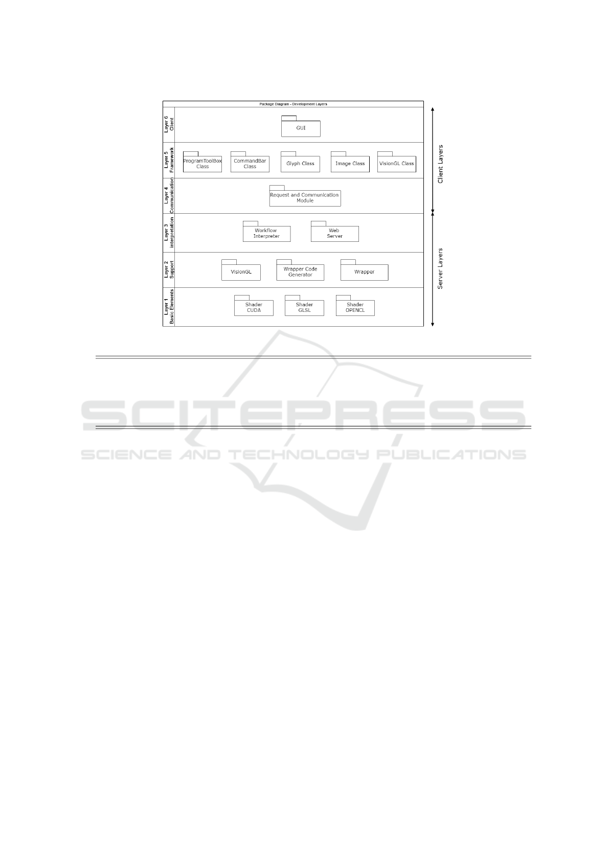
Figure 1: Package diagram: development layers (Maciel et al., 2021).
1 # Gly p h ’ [ Gly p h N a m e ] ’
2 Gl y p h :[ L i b r a r y ]:[ Gly p h N a m e ]: : l o c a l h o s t :[ Gl y p h _ I D ] :[ G l yph _ X ]: [ G l y p h_Y ]: : -[ va r _ s tr ] ’[ var_str_ v a l u e ] ’
3 Gl y p h :[ L i b r a r y ]:[ Gly p h N a m e ]: : l o c a l h o s t :[ Gl y p h _ I D ] :[ G l yph _ X ]: [ G l y p h_Y ]: : -[ va r _ n um ] [ v a r _ n u m _ v a l ue ]
4
5 # C o n n e c t i o n s ’ [ G lyphN a m e ] ’
6 N o d e C o n n e c t i o n : da t a :[ o u tp u t _ G l y ph _ I D ]: [ o u tp u t _ v a r n a me ]: [ i n p u t _ Gl y p h _ I D ]: [ i np u t _ v a r n a m e ]
Listing 1: Workflow file format.
tentially improved versatility in changing configura-
tions at the expense of longer runtimes (da F. Costa,
2020).
An interpreter is a program that analyzes source
code in real-time without compiling it first. The el-
ements of an interpreter are the lexer, which trans-
forms a simple text string into a sequence of tokens;
the parser, which takes a sequence of tokens and pro-
duces an abstract syntax tree (AST) of a language;
and the evaluator, which is a program that executes
the AST (Sakib Had
ˇ
ziavdi
´
c, 2020).
VGLGUI provides functionalities to create, edit,
execute and stop the execution of workflow files
through glyphs. A glyph is an iconic representation
of a function connected to others, forming a data pro-
cessing stream. Each glyph represents a VisionGL
function. Figure 1 shows the six layers of VGLGUI.
Each layer provides a strict and well-defined interface
with the layers above it. The workflow interpreter
is contained in layer 3, Interpretation (Maciel et al.,
2021).
A workflow consists of an orchestrated flow of
data processing components. A workflow can be de-
scribed as a sequence of work operations that can be
simple or complex (Traisuwan et al., 2015). Work-
flow means that work is done by different components
in a fixed sequence (Tong et al., 2011).
The workflow interpreter of the VGLGUI inter-
face has an architecture based on glyphs and connec-
tions. The relationship between them is governed by
the rules below.
1. A glyph corresponds to a graph vertex and repre-
sents a function from the VisionGL library.
2. An edge is a connection between glyphs and rep-
resents the image to be processed.
3. Each connection has an image stored.
4. A source-type glyph loads or creates an image and
has only output connections.
5. A sink-type glyph shows or saves an image and
has only input connections.
6. Glyphs have a READY status that informs if it is
ready to execute and a DONE status that informs
if it has already been executed. Both statuses start
as FALSE.
7. Connections whose input glyphs have already
been executed, therefore having their correspond-
VISAPP 2023 - 18th International Conference on Computer Vision Theory and Applications
814
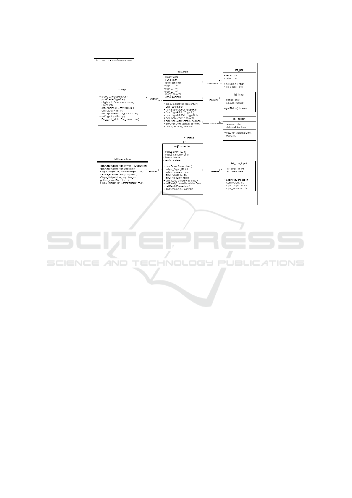
Figure 2: Class diagram: workflow interpreter.
ing images generated, have status READY =
TRUE, which means that the image is ready to be
processed.
8. Glyphs may have a list of input connections.
When all connections have status READY =
TRUE, the glyph changes its status to READY =
TRUE.
9. Source-type glyphs are created with status
READY = TRUE.
10. Glyphs whose status is READY = TRUE are exe-
cuted.
11. Glyph status becomes DONE = TRUE after its ex-
ecution.
Listing 1 shows the two types of command lines
used to create glyphs and connections based on the
Khoros workflow file format.
The programmer uses VGLGUI to develop his im-
age processing pipeline, and the interface generates
the corresponding workflow file on disk with the ex-
tension wksp.
To edit the image processing workflow in
VGLGUI, the user chooses the File - Open workflow
file option from the menu, indicates the file path, and
clicks on the Open button. The VGLGUI Interpreter
reads the glyph-type command lines, identifies the
information about the glyph—screen position, func-
tion to execute, and execution parameters—and cre-
ates the graphical representation of the glyph in the
VGLGUI Workspace. Then, the interpreter reads the
connection-type command lines and draws the graph-
ical representation of the connections in the VGLGUI
Workspace.
Each glyph input is linked to a single glyph output,
its immediate predecessor in the image processing se-
quence. On the other hand, each glyph output can be
connected to more than one glyph input.
The VGLGUI Interpreter generates an AST and
stores the information of the glyphs and their connec-
tions in memory, Figure 2 shows the classes used in
the internal representation of workflows in memory.
The VGLGUI Interpreter was developed in Python.
The user edits the workflow graphically, and when
clicking on the menu File - Save workflow file, the
changes are saved to disk. Error handling is per-
formed during the reading and execution of the work-
flow file to avoid basic program failures. Error mes-
sages show the workflow line with the error and the
rule not met.
3 RESULTS
This study demonstrates the usage of two sample
workflows with VGLGUI: Demo and Fundus. Demo
workflow shows the basic usage of the interpreter.
Fundus workflow shows a real-life scenario by seg-
menting a retinography image. For the sake of com-
parison, both workflows were tested with the same
sample image from the HRF dataset (Budai et al.,
High-Level Workflow Interpreter for Real-Time Image Processing
815
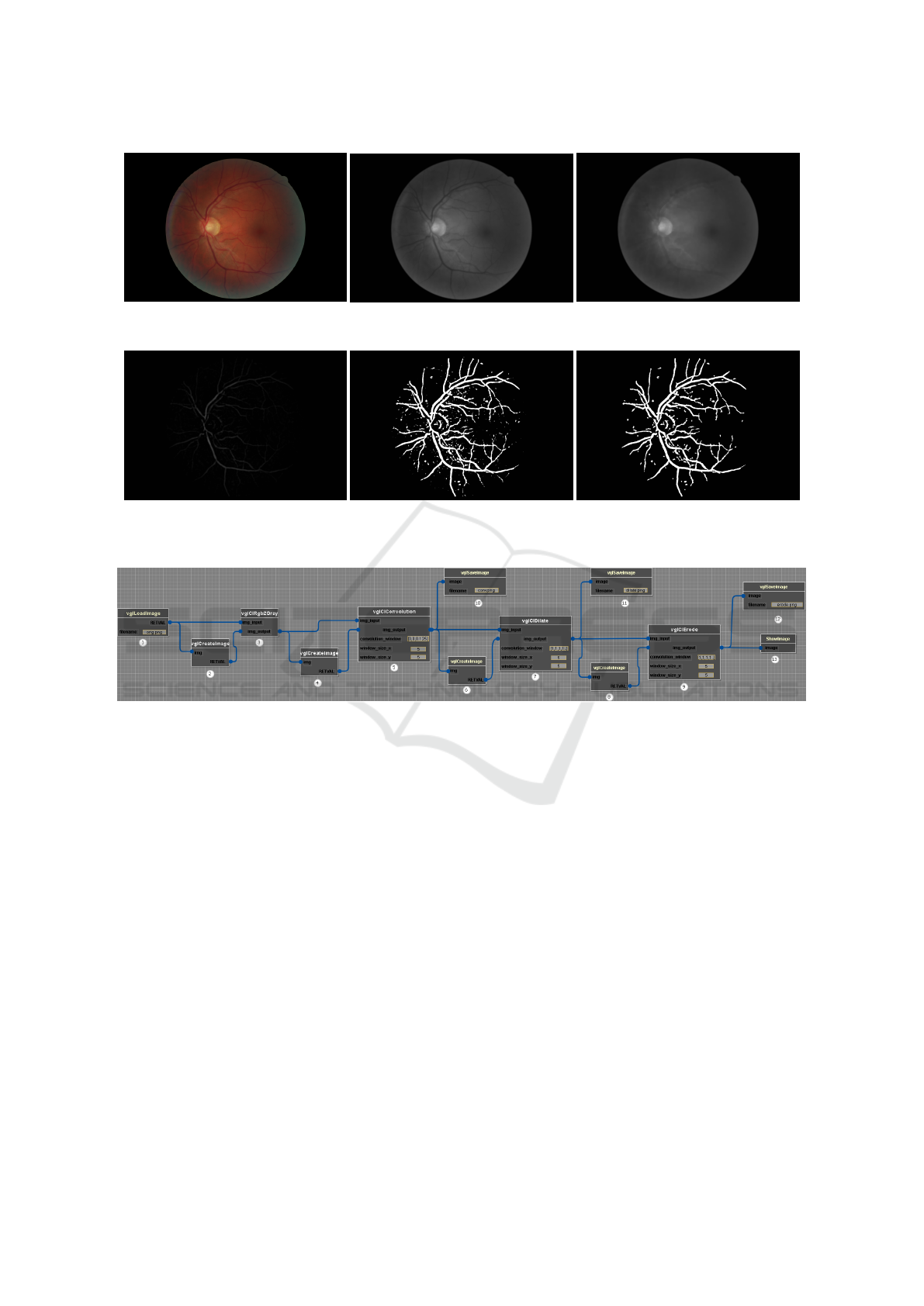
(a) Original image
(b) Convolution
(c) Closing
(d) Subtraction (e) Threshold (f) Reconstruction
Figure 3: Results of the Fundus image processing workflow.
Figure 4: Visual representation of the Demo workflow.
2013a; Budai et al., 2013b). Figure 3 shows the re-
sulting images of the Fundus image processing work-
flow. Both workflows were run on a desktop com-
puter with a CPU Intel Core i3-4130 3.40GHz with
12GB RAM and a GPU NVIDIA GeForce GTX 1070
with 8GB RAM. The workflows used basic opera-
tions such as image load, image save, convolution,
and mathematical morphology operations, such as di-
lation and erosion. The Fundus workflow also uses
subtraction, closing, and reconstruction operations.
The interpreter was tested with both workflows
running on the CPU and GPU. Both workflows were
also ported to Python with OpenCV running on the
CPU; and C++ with VisionGL running on the GPU.
3.1 Demo Workfow
The Demo workflow aims to demonstrate is to
demonstrate the usage of basic functions such as con-
volution, dilation, and erosion. Figure 4 is the visual
representation of the Demo workflow.
Glyph 1 loads the image to be processed. Glyph
2 allocates an image with the same size as the in-
put image required by vglClRgb2Gray. Glyph 3
applies the vglClRgb2Gray function to convert the
input image to grayscale. The VisionGL function
vglClConvolution applies a Gaussian blur to reduce
noise. Glyph 10 saves the result of the convolution to
a file. Glyph 7 applies the vglCLDilate function to
increase the bright areas. Glyph 8 allocates an im-
age of the same size as the input image required by
vglClErode. Glyph 12 saves the result of the ero-
sion to a file. Glyph 9 executes the vglClErode to
eliminate bright areas smaller than the structuring el-
ement. Glyph 13 shows the resulting final image on
the screen.
Table 1 shows the execution times of the Demo
image processing workflow in milliseconds.
VISAPP 2023 - 18th International Conference on Computer Vision Theory and Applications
816

3.2 Fundus Workflow
In the Fundus workflow, the objective is the appli-
cation of a pipeline for blood vessel segmentation
in retinal images (Dantas et al., 2017). The general
steps of the pipeline are convolution (Gaussian blur),
closing and subtraction (black-hat), thresholding, and
opening by reconstruction. The filters and structuring
elements were separated into a column filter and a line
filter. The results are identical, but the time complex-
ity is much lower.
Figure 3 shows the resulting images from the Fun-
dus image processing workflow. Table 2 shows the
processing times in milliseconds.
3.3 Discussion
The workflow interpreter, whose structure was de-
tailed in this study, is a layer of the VGLGUI ar-
chitecture that links the VisionGL functions and the
graphical interface to facilitate the learning of im-
age processing pipeline programming. VGLGUI uses
OpenCL to parallelize processing on the GPU.
In VGLGUI, the developer elaborates his image
processing pipeline without coding. The functions
are chosen from a menu generated from the func-
tions available in VisionGL. If necessary, the user can
create his own functions in OpenCL, and the library
will automatically generate its wrapper functions and
menu entries. These features improve the learning
curve of novice programmers and accelerate develop-
ment.
Two workflows were created to demonstrate how
the interpreter works. Demo workflow demonstrates
the usage of basic functions. Fundus workflow
demonstrates the usage in a real-life scenario by seg-
menting a retinography image. Both workflows were
tested with an image with about 18 megapixels. Both
workflows were ported to Python and C++, and the
runtimes were obtained.
The average processing time of the Demo work-
flow by the interpreter running on the GPU was 62.65
ms and by the Python version running on the CPU
was 437.07 ms. Thus the interpreter can run a simple
workflow a few times faster than Python. GPU oc-
cupancy was low in this workflow, meaning that the
Python calls done by the interpreter and that run on
the CPU cause a bottleneck when GPU operations are
too fast.
On the other hand, the interpreter’s average pro-
cessing time by the Fundus workflow on the GPU was
916.05 ms, while the Python version on the CPU was
more than 1300000 ms. Fundus workflow runs on the
GPU hundreds of times faster than its Python version.
Table 1: Demo workflow runtime, in milliseconds, on an
image with 5184×3456 pixels.
Python Interpreter VisionGL
Operations
CPU CPU GPU GPU
Rgb2Gray
7.46 342.18 1.35 1.36
Convolution 51×51
357.72 18119.85 21.36 20.38
Dilation 51×51
35.06 19659.90 19.95 18.78
Erosion 51×51
36.83 20294.23 19.99 18.80
TOTAL
437.07 58416.16 62.65 59.32
Table 2: Fundus workflow runtime, in milliseconds, on an
image with 5184×3456 pixels.
Python Interpreter VisionGL
Operations
CPU CPU GPU GPU
Rgb2Gray
5.42 301.89 1.39 1.33
Convolution 51×51
358.66 17861.99 22.07 20.55
Closing 51×51
64.06 38960.01 40.87 38.76
Subtraction
4.22 475.56 1.03 1.03
Threshold
36.49 475.56 1.03 0.71
Reconstruction 17×17
1321649.79 1301049.64 849.61 1002.88
TOTAL
1428427.05 1359124.65 916.05 1065.26
As the reconstruction takes a long time to complete,
GPU occupancy is higher, and the CPU bottleneck
impairs less the processing speed. Frequent transfers
of data between the RAM and the GPU memory also
may cause a bottleneck. As the image is transferred
only once from the RAM to the GPU memory and
there remains during the whole workflow processing,
there is no latency associated with that.
The runtimes of the workflows implemented in
C++ with VisionGL running on the GPU were sim-
ilar to the runtimes of the workflows processed by the
interpreter running also on the GPU.
4 CONCLUSIONS
This study proposes a workflow interpreter to facil-
itate the implementation of image processing work-
flows that support parallelization by using OpenCL.
The speedup varies between one to three orders
of magnitude compared to a Python version using
OpenCV and running on the CPU. Part of this vari-
ation may be due to the CPU bottleneck, which is rel-
atively narrower when the functions that run in the
GPU are too fast. When the operations that run in the
GPU are more demanding, e.g., composed of many
window operations such as the reconstruction, GPU
occupancy increases, and the speedup is bigger.
The proposed system also can facilitate the im-
plementation of image processing pipelines by pro-
viding a visual workflow editor. Visual programming
may be easier and more intuitive to use than standard
programming languages and may also accelerate the
High-Level Workflow Interpreter for Real-Time Image Processing
817

development by providing a ready-to-use testbed for
image processing experiments.
Future versions of VGLGUI may include new im-
age processing functions, either by augmenting Vi-
sionGL or exposing image processing functions from
OpenCV. We are also considering the implementation
of a scheduler to distribute the load across servers.
The authors thank CNPq for the financial support.
REFERENCES
Blattner, T., Keyrouz, W., Halem, M., Brady, M., and Bhat-
tacharyya, S. S. (2015). A hybrid task graph scheduler
for high performance image processing workflows. In
2015 IEEE Global Conference on Signal and Informa-
tion Processing (GlobalSIP), pages 634–637. IEEE.
Budai, A., Bock, R., Maier, A. K., Hornegger, J.,
and Michelson, G. (2013a). High-Resolution Fun-
dus (HRF) Image Database. [Online]. Available:
https://www5.cs.fau.de/research/data/fundus-images/.
Budai, A., Bock, R., Maier, A. K., Hornegger, J., and
Michelson, G. (2013b). Robust vessel segmentation
in fundus images. International Journal of Biomedi-
cal Imaging, 2013.
Cao, H., Jin, H., Wu, S., and Ibrahim, S. (2009). Image-
Flow: Workflow based image processing with legacy
program in grid. In 2009 Second International Con-
ference on Future Information Technology and Man-
agement Engineering, pages 115–118. IEEE.
da F. Costa, L. (2020). Distributed systems through a simple
interpreter (CDT-49).
Dantas, D. O., De Souza Oliveira, D., and Leal, H. D. P.
(2017). Blood vessels extraction using fuzzy mathe-
matical morphology. In 2017 IEEE International Con-
ference on Acoustics, Speech and Signal Processing
(ICASSP), pages 914–918. IEEE.
Dantas, D. O., Leal, H. D. P., and Sousa, D. O. B.
(2016). Fast multidimensional image processing with
OpenCL. In International Conference on Image Pro-
cessing (ICIP), pages 1779–1783. IEEE.
Gal, N. and Stoicu-Tivadar, V. (2011). Simulation of medi-
cal image interpretation. In 2011 15th IEEE Interna-
tional Conference on Intelligent Engineering Systems,
pages 33–37.
Gurevich, I. B., Khilkov, A. V., Koryabkina, I. V.,
Murashov, D. M., and Trusova, Y. O. (2006). An
open general-purposes research system for automat-
ing the development and application of information
technologies in the area of image processing, analysis
and evaluation. Pattern Recognition and Image Anal-
ysis, 16(4):530–563.
Hamidian, H., Lu, S., Rana, S., Fotouhi, F., and Soltanian-
Zadeh, H. (2014). Adapting medical image process-
ing tasks to a scalable scientific workflow system. In
2014 IEEE World Congress on Services, pages 385–
392. IEEE.
Kaewkeeree, S. and Tandayya, P. (2012). Enhancing the
Taverna workflow system for executing and analyz-
ing the performance of image processing algorithms.
In 2012 Ninth International Conference on Computer
Science and Software Engineering (JCSSE), pages
328–333. IEEE.
Li, B., Sallai, J., V
¨
olgyesi, P., and L
´
edeczi, A. (2012). Rapid
prototyping of image processing workflows on mas-
sively parallel architectures. In Proceedings of the
10th International Workshop on Intelligent Solutions
in Embedded Systems, pages 15–20. IEEE.
Maciel, R., Soares, M., and Dantas, D. (2021). A system
architecture in multiple views for an image process-
ing graphical user interface. In In Proceedings of the
23rd International Conference on Enterprise Informa-
tion Systems (ICEIS), pages 213–223. SCITEPRESS.
Milletari, F., Frei, J., Aboulatta, M., Vivar, G., and Ahmadi,
S.-A. (2019). Cloud deployment of high-resolution
medical image analysis with TOMAAT. Journal of
Biomedical and Health Informatics, 23(3):969–977.
Park, J. H., Nadeem, S., Mirhosseini, S., and Kaufman, A.
(2016). C2A: Crowd consensus analytics for virtual
colonoscopy. 2016 IEEE Conference on Visual Ana-
lytics Science and Technology (VAST).
Queir
´
os, S., Morais, P., Barbosa, D., Fonseca, J. C., Vilac¸a,
J. L., and D’Hooge, J. (2018). MITT: Medical Im-
age Tracking Toolbox. IEEE Transactions on Medical
Imaging, 37(11):2547–2557.
Sakib Had
ˇ
ziavdi
´
c (2020). How to approach writing an
interpreter from scratch. [Online]. Available: https:
//www.toptal.com/scala/writing-an-interpreter.
Sozykin, A. and Epanchintsev, T. (2015). MIPr - a frame-
work for distributed image processing using Hadoop.
In 2015 9th International Conference on Applica-
tion of Information and Communication Technologies
(AICT), pages 35–39.
Tong, J., Cheng-Dong, W., and Dong-Yue, C. (2011). Re-
search and implementation of a digital image process-
ing education platform. In 2011 International Con-
ference on Electrical and Control Engineering, pages
6719–6722. IEEE.
Traisuwan, A., Tandayya, P., and Limna, T. (2015). Work-
flow translation and dynamic invocation for image
processing based on OpenCV. In 2015 12th In-
ternational Joint Conference on Computer Science
and Software Engineering (JCSSE), pages 319–324.
IEEE.
Wang, J. and Hogue, A. (2020). CVNodes: A visual pro-
gramming paradigm for developing computer vision
algorithms. In 17th Conference on Computer and
Robot Vision (CRV), pages 174–181. IEEE.
Young, M., Argiro, D., and Kubica, S. (1995). Cantata:
Visual programming environment for the Khoros sys-
tem. SIGGRAPH Computer Graphics, 29(2):22–24.
VISAPP 2023 - 18th International Conference on Computer Vision Theory and Applications
818
