
Mode Analysis of Hybrid Plasmonic Waveguide Using Multilayer
Spectral Green’s Function and Rational Function Fitting Method
Abdorreza Torabi
School of Engineering Science, College of Engineering, University of Tehran, Tehran, Iran
Keywords: Hybrid Plasmonic Waveguide, Spectral Green’s Function, Rational Function Fitting, Surface Plasmon,
Effective Refractive Index, Propagation Length.
Abstract: A fast and accurate approach to find hybrid plasmonic waveguide mode and its properties is presented in this
paper. The method is based on rational function fitting of spectral Green’s function of layered hybrid
plasmonic waveguide with the use of modified VECTFIT algorithm. Complex modes including surface
plasmonic modes of structures with insulator/metal loss can be obtained. The main advantage of this method
lies in its simple implementation, speed as well as controllable accuracy. Effective index and propagation
length versus thickness of layers are evaluated and excellent agreements with rigorous COMSOL solution
(finite element method) are shown.
1 INTRODUCTION
Surface plasmons (SPs) are the interaction of surface
electrons of metals with the electromagnetic fields.
Unlike surface wave (SW) modes of dielectric
waveguide, SPs modes are localized and propagate
along interface between dielectric and metal which
several optical modules can be developed on the scale
of nanometre based on this concept and make these
modules widely utilized in information technology,
energy and biology (Zia, et all. 2004, Brongersma and
Kik 2007, Chang and Tai 2011, Kalavrouziotis, et all.
2012).
Plasmonic waveguides have advantages of mode
size and diffraction limit over the dielectric
waveguides while they suffer from large losses due to
metal presence. Hybrid plasmonic waveguide (HPW)
does not suffer from large losses and diffraction limit
due to confinement of mode power in low refractive
index region. Various configurations of metal and
insulator are reported as HPW structures and for
applications like communication (fundamental mode
propagation) and biology (multimode propagation)
(Sharma and Kumar 2017).
Dispersion equations can be obtained by solving
Maxwell’s equations for the given geometry and
applying proper boundary conditions at the interfaces.
In general, dispersion equations have no analytic
closed-form solutions and therefore using numerical
approach is inevitable. Bisection method (Press, et.
all. 1988) for lossless and argument principle method
(APM) (Anemogiannis and Glytsis 1992, Kocabas, et
all. 2009) for lossy structures can be utilized to have
real and complex solutions of modes respectively.
APM gives nearly accurate results but the main
challenge is its computation time especially for
structures supporting large number of modes.
There are also some other techniques which
require exact programming defined for special
problem and are not efficient in general (Press, et. all.
1988, Anemogiannis, et all. 1999, Zia, et all. 2004).
For instance, high sensitivity to initial guesses
provided by user is another important challenge of
these methods. On the other hand, although full
numerical solution like finite difference time domain
(FDTD) method (Feigenbaum and Orenstein, 2007)
can extract the parameters and physical picture of
plasmonic waveguides but this method usually
suffers from intensive computational cost. Scattering
matrix (S-matrix) method along with finite difference
frequency domain (FDFD) (Kocabas, et all. 2008) can
be useful in modal analysis but commonly the form
of the derivations are not suitable to handle the field
distribution.
In this paper rational function fitting of spectral
Green’s function (SGF) is used for fast mode
analysis of HPW of Figure. 1. Modified VECTFIT
28
Torabi, A.
Mode Analysis of Hybrid Plasmonic Waveguide Using Multilayer Spectral Green’s Function and Rational Function Fitting Method.
DOI: 10.5220/0011647300003408
In Proceedings of the 11th International Conference on Photonics, Optics and Laser Technology (PHOTOPTICS 2023), pages 28-33
ISBN: 978-989-758-632-3; ISSN: 2184-4364
Copyright
c
2023 by SCITEPRESS – Science and Technology Publications, Lda. Under CC license (CC BY-NC-ND 4.0)

algorithm is used for rational function fitting process
extracting complex modes including surface
plasmonic modes of the structure. The speed of the
method allows us to evaluate the behaviour of the
effective index and propagation length against
thickness of the layers of the structure effectively.
Advantages of simple implementation as well as
accuracy of this method are shown and verified for
HPW like Figure. 1.
This paper is organized as following. In section 2,
rational function fitting of SGF for HPW is described.
Numerical results and validations of the method are
presented in section 3 while some concluding remarks
are given in section 4.
Figure 1: Schematic of HPW waveguide (MIM).
2 RATIONAL FUNCTION
FITTING OF SGF FOR HPW
Consider a 2D (no variation in z direction) hybrid
metal-insulator-metal layered plasmonic waveguide
(Fig. 1) which has a dielectric region (#3) with high
refractive index like Si with thickness
h
t
placed
between two low refractive index dielectric regions
(#2, 4) like SiO
2
with thickness
l
t
and two metal
layers (#1, 5) like Ag with thickness
m
t
. We have z-
axis propagation with x-y plane confinement.
We first derive the vector potential Green’s
function of a line source located in
(, )xy
¢¢
and field
point in
(, )xy both in region 3 with usual spectral
technique (Michalski and Mosig 1997):
(1)
(1)
where
3,2
m
R
and
3,4
m
R
can be found by recursive
relations:
1
1
2
1, , 1
1,
2
1, , 1
1
1,
1
1
//
//
yi
i
yi
i
ii
ii
jt
mm
ii ii
m
ii
jt
mm
iiii
yi yi
m
ii
yi yi
rRe
R
rRe
r
+
+
-b
+-
+
-b
+-
+
+
+
+
=
+
be-be
=
be+be
1, 2, 3i =
(2)
1
1
1
1
1
2
,1 1,2
,1
2
,1 1,2
1
,1
1
1
//
//
yi
i
yi
i
ii
ii
jt
mm
ii i i
m
ii
jt
mm
ii i i
yi y i
m
ii
yi y i
rRe
R
rR e
r
+
+
+
+
+
-b
+++
+
-b
+++
+
+
+
+
=
+
be-b e
=
be+b e
3, 4i =
(3)
in (2) and (3),
2
ii
ne=
is the relative dielectric constant
of region i. in (1), y
>
and y
<
are the greater and
smaller values of
y
and
y
¢
respectively.
𝛽
𝑛
𝑘
𝛽
,
𝑖0,1,...,6
where 𝑘
2𝜋/𝜆 and
l
is free space wavelength and
x
b is the propagation
constant of x direction. For
1,0
m
R
and
5,6
m
R
, they are the
reflection coefficients of light for semi-infinite layer
of air, and we will have
1,0 1,0 5,6 5,6
,
mmm m
RrRr==
.
Relation (1) to (3) are general for 5 layered structures,
while in our considered case, due to symmetry
(similarity of two metal layers (regions 1 and 5) and
two low refractive index insulator layers (regions 2
and 4)), we have
𝑅
,
𝑅
,
,𝑅
,
𝑅
,
,𝑅
,
𝑅
,
.
m
A
G
includes transverse magnetic (TM) SW and
SP modes which are the zeros of denominator of SGF.
Modified version of VECTFIT algorithm has
been successfully applied to SGF like (1) to fit it with
rational form which corresponds to spectral form of
surface modes. Indeed here we have an
approximation below with total number of M poles
(Torabi, et. all. 2013, Torabi and Shishegar 2015,
Torabi 2019):
(4)
that
xp
b and R
p
are p-th computed pole and its
residue of
m
A
G
respectively. Sampling of
x
b
from straight line
[]
max 0 max 0
,kj kj-t - dt + d
with
Mode Analysis of Hybrid Plasmonic Waveguide Using Multilayer Spectral Green’s Function and Rational Function Fitting Method
29

Table 1: Results of the proposed and APM (Anemogiannis and Glytsis 1992) for defined structure above.
Mode number
Real( )
eff
n
Imaginary( )
eff
n
Proposed method
APM (Anemogiannis
and Glytsis 1992)
Proposed method
APM (Anemogiannis
and Glytsis 1992)
00
TM
1.740200419 1.740200909 0.002165046 0.002165111
01
TM
1.124098123 1.124098306 0.003525932 0.003525802
appropriate values of 𝜏
and
d
is the first step of
VECTFIT algorithm. Construction of auxiliary
matrix for sample points
𝛽
,𝐺
𝑦,𝑦
′
,𝛽
in each
iteration, is the next step where its eigenvalues are the
approximate poles for the next step. Then using least
square technique for a linear equation,
p
R would be
found for each pole. We can have criteria for relative
error as (5) to control the accuracy and required
number of poles. Modified VECTFIT algorithm is
very fast and relative error of
10
for (5) can be
obtained with
10 ∼ 15 poles typically less than 0.5
second.
(5)
Extracted poles of modified VECTFIT algorithm
includes all SW and SP modes (solution of the
dispersion equations or in other words the zeros of the
denominator of SGF) as well as some other poles
which are representatives of continuous spectrum
contributions called radiation modes. SW and SP
modes of the SGF are independent of the source
𝑦
′
and filed point
𝑦
location. On the other hand
radiation modes re perfectly dependent to
𝑦 and 𝑦
′
.
This fact comes from construction of continuous
spectrum of radiation modes which depends on the
location of excitation and observation points (Torabi,
et. all. 2013). Each pole that makes the denominator
of
m
A
G
zero belongs to group of SP and SW modes
otherwise it belongs to group of radiation modes.
To start the algorithm, poles (
𝛽
) and their
related residuals ( R
p
s) should be initially set. It is
obvious that, if the initial poles are close to the exact
answers, then the algorithm will converge fast.
Therefore, in each iteration of the VECTFIT
algorithm, the poles extracted in the previous step are
used as initial poles. It should be noted that one of the
main advantages of the proposed RFF-SGF method is
that the used modified VECTFIT algorithm does not
depend on the first starting the initial guesses of the
poles. In other words, the modified VECTFIT
algorithm is robust enough that its convergence does
not depend on the first initial guess (Gustavsen and
Semlyen 1999). Therefore, in all simulations, one can
choose random
p
N
values in region
[]
max 0 max 0
,kj kj-t - dt + d
as first initial guesses
(first iteration) of poles.
3 RESULTS
In Fig. 1, suppose regions 1 and 5 as Ag with 𝜀
143.5 𝑗9.5
, 300
m
tnm= , region 2 and 4 as SiO
2
with
𝜀
2.1,100
l
tnm= and region 3 as Si with
𝜀
12.2, 100
h
tnm= . Table. 1 shows effective
indices of the first two TM modes of this structure at
1.55 ml= m
. Results are compared with Argument
Principle Method (APM) (Anemogiannis and Glytsis
1992, Kocabas, et all. 2009)
and excellent agreements
can be seen for computed results. Also the total time
of (4) is nearly 1/30of the APM (proposed method: 2
sec and APM: 1 min). High speed of the VECTFIT
algorithm help us to have mode analysis of HMIM.
The real and imaginary part of effective refractive
index are related to modal index and the propagation
length (
𝑃𝑙 𝜆/4𝜋 𝐼𝑚𝑛
) respectively.
Propagation length of a mode is defined as a distance
over which the guided power is reduced to nearly 37
%of the initial power. It is desired that by increasing
the thickness of high index region (region 3-Si), the
resulted HPW would be similar to a dielectric
waveguide. Moreover it can be seen that the first
mode (
𝑇𝑀
) results in stronger light confinement
than the second mode (Figure. 2). Moreover, Figure.
2 shows increasing in propagation length by
increasing Si thickness (
𝑡
ℎ
). Reversely it is desired
that by increasing the low refractive index regions
(region 2 and 4) the nature of HPW turns towards to
plasmonic waveguide. Figure. 3 shows decreasing in
real part of effective index and increasing of
propagation length for
00
TM with increasing of
l
t .
PHOTOPTICS 2023 - 11th International Conference on Photonics, Optics and Laser Technology
30
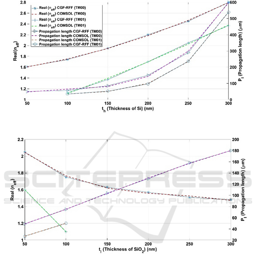
Figure 2: Real part of effective index and propagation length versus
h
t .Regions 1, 5 as Ag with 𝜀
143.5 𝑗9.5, 𝑡
300𝑛𝑚, region 2, 4 as SiO2 with 𝜀
2.1, 𝑡
100𝑛𝑚, region 3 as Si with 𝜀
12.2.
Figure 3: Real part of effective index and propagation length versus
l
t .Regions 1, 5 as Ag with 𝜀
143.5 𝑗9.5,𝑡
300𝑛𝑚, region 2, 4 as SiO
2
with 𝜀
2.1, region 3 as Si with𝜀
12.2,𝑡
ℎ
100𝑛𝑚 (Legends are similar to Fig. 2).
For 𝑡
100𝑛𝑚we will have 𝑇𝑀
mode. Results of
COMSOL simulations (dashed lines) are also shown
in Figure. 2 and 3. Excellent agreement can be seen.
4 CONCLUSIONS
A new approach for SP modes evaluation and modal
analysis of hybrid plasmonic waveguide is presented
in this paper. The method is based on the rational
function fitting of the spectral Green’s function of the
desired multilayered plasmonic structure. Modified
VECTFIT algorithm is used to rational function
fitting process and related SP modes of the structure
would be extracted. The main requirement of this
method is derivation of the spectral Green’s function
of the structure once which have a closed form
relation. Simple and fast implementation while
preserving accuracy are the main advantages of the
proposed method which are validated by exact
rigorous results of COMSOL (finite element
method).
Mode Analysis of Hybrid Plasmonic Waveguide Using Multilayer Spectral Green’s Function and Rational Function Fitting Method
31

REFERENCES
Anemogiannis, E., et all. (1999). Determination of guided
and leaky modes in lossless and lossy planar multilayer
optical waveguides: reflection pole method and
wavevector density method. J. Lightwave Technol.
17(5), 929.
Anemogiannis, E., Glytsis, E. (1992). Multilayer
waveguides: efficient numerical analysis of general
structures, J. Lightwave Technol. 10(10), pp. 1344–
1351.
Brongersma, M., Kik, P. (2007). Surface Plasmon
Nanophotonics, Springer Series in Optical Sciences.
Springer, New York.
Chang, S., Tai, C. (2011). Broadband energy conversion
between off-plane gaussian lightwave and in-plane
surface plasmon waves. IEEE Photon. Technol. Lett.
23(22), 1727–1729.
Feigenbaum, E., Orenstein, M., (2007). Modeling of
complementary (void) plasmon waveguiding. J.
Lightwave Technol. 25(9), 2547– 2562.
Gustavsen, B., Semlyen, A., (1999). Rational
approximation of frequency domain responses by
vector fitting. IEEE Trans. Power Deliv. 14(3), 1052–
1061.
Kalavrouziotis, D., et all. (2012). Demonstration of a
plasmonic mmi switch in 10-gb/s true data traffic
conditions. IEEE Photon. Technol. Lett. 24(20), 1819–
1822.
Kocabas, S., et all. (2008). Transmission line and
equivalent circuit models for plasmonic waveguide
components. IEEE J Select. Top. Quantum Electron.
14(6), 1462–1472.
Kocabas, S., et all. (2009). Modal analysis and coupling in
metal-insulator-metal waveguides. Phys. Rev. B 79,
035120.
Michalski, K., Mosig, J,. (1997). Multilayered media
Green’s functions in integral equation formulations.
IEEE Trans. Antennas Propagat., 45(3), 508–519.
Press, W., et. all. (1988). Numerical Recipes in C: The Art
of Scientific Computing, Cambridge University Press,
New York.
Sharma, P., Kumar, V. (2017). Hybrid Insulator Metal
Insulator Planar Plasmonic Waveguide-Based
Components, IEEE Photonics Technology Letters, vol.
29, pp. 1360-1363.
Torabi, A., (2019). An efficient plasmonic waveguide mode
solution using rational function fitting of Green’s
function. J. optical review., 26(2): 278-282.
Torabi, A., et. all. (2013). An efficient closed-form
derivation of spatial Green’s function for finite
dielectric structures using characteristic Green’s
function-rational function fitting method, IEEE Trans.
Antennas Propagat., 62(3).
Torabi, A., Shishegar, A. A., (2015). Combination of
Characteristic Green's Function Technique and
Rational Function Fitting Method for Computation of
Modal Reflectivity at the Optical Waveguide End-
Facet, 3th International conference on photonics, optics
and laser technology (PHOTOPTICS 2015).
Zia, R., et all. (2004). Geometries and materials for
subwavelength surface plasmon modes. J. Opt. Soc.
Am. A 21(12), 2442–2446.
APPENDIX
Modified Vectfit Algorithm
Suppose that the samples of 𝐺
𝑦,𝑦
′
,𝛽
at
s
x
i
b
, 𝑖
1,2,...,𝐿
are provided and are shown by 𝐺
𝛽
(ignoring
y
and
y
¢
for simplicity). If 𝛽
,𝑝
1,2,...,𝑀
be an initial guess for the poles of (4), then
for every
xi
b
one can form
𝑬
𝒓𝑔
(6)
Where
(7)
and
(8)
where sign “
%
” and “
T
” denotes complex conjugate
and transpose operator. For all
xi
b
points, we reach
to a linear and over determined system like the
following:
𝑬𝒓 𝒈 (9)
where
E
is a 𝐿
2𝑀
matrix which its ith row is
given by (7) and
g
is a column vector of
i
g .
(10)
𝒈𝐺
𝛽
,...,𝐺
𝛽
(11)
By solving (9), a new set of poles which are closed
to the poles of
m
A
G
can be obtained as the eigenvalues
of a
Q
matrix defined as following:
PHOTOPTICS 2023 - 11th International Conference on Photonics, Optics and Laser Technology
32
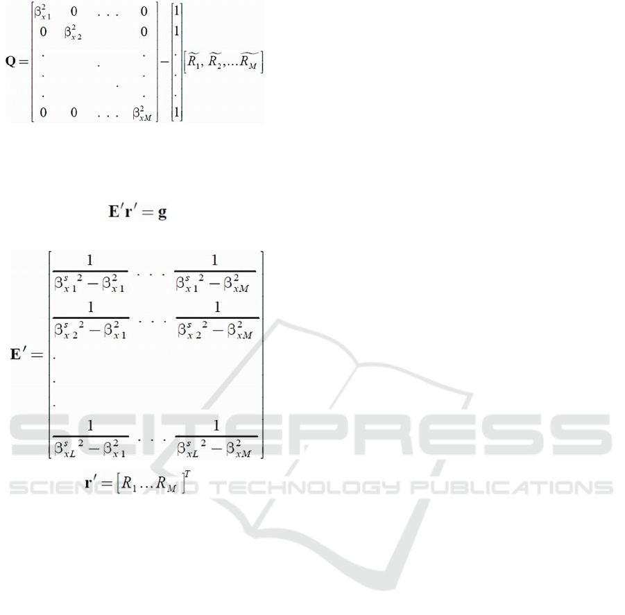
(12)
Then by applying the iteration form, poles of the last
iteration would be utilized as the starting poles of the
next iteration. After a good convergence,
𝑅
𝑠 can be
found by solving a linear system as following:
(13)
where
𝑬
′
is 𝐿𝑀matrix and 𝒓
′
is vector given below:
(14)
(15)
Vector
g
is given by (11).
Mode Analysis of Hybrid Plasmonic Waveguide Using Multilayer Spectral Green’s Function and Rational Function Fitting Method
33
