
Coverage-Guided Fuzzing for Plan-Based Robotics
Tim Meywerk
1 a
, Vladimir Herdt
1,2 b
and Rolf Drechsler
2 c
1
Group of Computer Architecture, University of Bremen, Bremen, Germany
2
Cyber-Physical Systems, DFKI GmbH, Bremen, Germany
Keywords:
Plan-based robotics, Safety, Fuzzing.
Abstract:
Autonomous robots are used increasingly in dynamic and safety-critical environments. In these environments
the correctness of the robotic plan is of utmost importance. In many other domains, coverage-guided fuzzing
has proven to be an effective way to ensure the correctness of software programs. In coverage-guided fuzzing,
inputs to a program are generated semi-randomly and the correctness of the output is checked automatically.
This way, a large number of test cases can be run without manual interaction. In this work we present our
approach to coverage-guided fuzzing for plan-based robotics and our prototypical implementation for the
planning language CPL. We also introduce a novel coverage metric for the domain of plan-based robotics.
1 INTRODUCTION
Autonomous robots are used increasingly in dynamic
and safety-critical environments. One promising ap-
proach to deal with the complexity of such environ-
ments are plan-based robotics. Here, a high-level plan
is responsible for the orchestration of several lower-
level modules that handle specialized tasks like navi-
gation or manipulation. When autonomous robots act
in safety-critical environments e. g. when they are in-
teracting with humans, the correctness of the high-
level plan is of utmost importance.
The most common method to ensure the plan’s
correctness are manual test runs in a simulation en-
vironment. However, these tests are often not per-
formed in a systematic fashion. Even a systematic
and thorough manual test will usually miss some im-
portant edge cases. An alternative to simulation-based
testing is formal verification (Luckcuck et al., 2019;
Meywerk et al., 2019). Formal verification is able
to cover the complete plan including all edge cases.
However, this completeness comes with the downside
of a high runtime and no guaranteed termination. De-
pending on the complexity of the plan, formal verifi-
cation methods may not terminate at all or only after
an unreasonably long time.
In many other domains, coverage-guided fuzzing
has proven to be an effective compromise be-
a
https://orcid.org/0000-0002-5960-5456
b
https://orcid.org/0000-0002-4481-057X
c
https://orcid.org/0000-0002-9872-1740
tween hand-written tests and formal verification. In
coverage-guided fuzzing, inputs to a program are gen-
erated semi-randomly and the correctness of the out-
put is checked automatically. This way, a large num-
ber of test cases can be run without manual interac-
tion. During execution, the coverage on the code is
measured and used to guide the generation of subse-
quent inputs. The goal is to maximize the coverage of
the generated test cases.
This way coverage-guided fuzzing is able to test
relevant edge cases that a human test engineer may
have missed. At the same time, coverage-guided
fuzzing can be terminated at any time and has no sig-
nificant runtime overhead over manual tests.
In this work we present our approach to coverage-
guided fuzzing for plan-based robotics. Our contri-
butions are threefold: First, we introduce coverage-
guided fuzzing to the domain of plan-based robotics.
Secondly, we present a prototypical implementation
for the robotic planning language CPL. Finally, we
introduce a novel coverage metric for the domain of
plan-based robotics that may be used in combination
with coverage-guided fuzzing or independently of it.
Our approach builds upon the robotic planning
language CPL and the CPL interpreter SEECER to
execute the robotic plan in a simulation. The fuzzer is
used to provide SEECER with different initial states
of the simulation as input to the plan. During execu-
tion the resulting code coverage is measured and fed
back to the fuzzer.
Our novel coverage metric measures the percent-
106
Meywerk, T., Herdt, V. and Drechsler, R.
Coverage-Guided Fuzzing for Plan-Based Robotics.
DOI: 10.5220/0011630600003393
In Proceedings of the 15th International Conference on Agents and Artificial Intelligence (ICAART 2023) - Volume 2, pages 106-114
ISBN: 978-989-758-623-1; ISSN: 2184-433X
Copyright
c
2023 by SCITEPRESS – Science and Technology Publications, Lda. Under CC license (CC BY-NC-ND 4.0)

1 ( perform ( an a c t i o n
2 ( t y p e p ic ki ng −u p )
3 ( arm : l e f t )
4 ( g r a s p l e f t − s i d e )
5 ( o b j e c t ? o b j e c t ) ) ) ) )
Figure 1: Performing an action designator in CPL.
age of possible actions that have been executed by the
plan and thus follows the effect of the plan on its en-
vironment more closely than general structural cover-
age metrics.
The remainder of this paper is structured as fol-
lows. In Section 2 we present relevant background
necessary for the understanding of this paper. Af-
terwards, Section 3 discusses related work in the
domains of coverage-guided fuzzing and plan-based
robotics. Section 4 presents our first two contri-
butions, namely our approach to coverage-guided
fuzzing for plan-based robotics in general and for
CPL in particular. The third contribution, our domain-
specific coverage metric is introduced in Section 5.
Section 6 discusses the experimental evaluation of our
approach and Section 7 concludes the paper.
2 PRELIMINARIES
This section introduces relevant background to the
work presented in this paper. This includes the
CRAM Planning Language in Section 2.1 and an
overview of coverage-guided fuzzing in Section 2.2.
2.1 CRAM Planning Language
The CRAM Planning Language (CPL) is part of the
robotic framework Cognitive Robot Abstract Machine
(CRAM). CRAM is a framework that handles all as-
pects of high-level robotic planning including mod-
ules for perception, navigation, manipulation and rea-
soning. The orchestration of the modules is achieved
through generalized plans in the high-level planning
language CPL.
CPL is built on top of the Common Lisp program-
ming language. It interacts with the robots environ-
ment through the use of action designators. Instead
of describing every aspect of an action in concrete
values, a designator is an abstract representation of
an action, for which concrete values are found only at
runtime. Designators are executed using the perform
keyword.
Example 1. Consider the plan excerpt in Figure 1.
The an keyword builds a designator, which is then
executed by the perform function. Each designator
Fuzzer
byte
array
SUT
Input
Transformation
valid
input
coverage
Figure 2: General coverage-guided fuzzing flow.
is defined through a list of key-value pairs. Here, the
type key is always present and describes the type of
the action. The other keys depend on the type of the
action. The action in Figure 1 is a picking-up action
that uses the left arm of the robot, a grasp from the
left side and is applied to the object stored in the vari-
able ?object. Other parameters of the action such
as the concrete trajectory of the joints are inferred at
runtime.
Another important module within CRAM is the
fast projection simulator (Mösenlechner and Beetz,
2013) based on the Bullet physics engine. The sim-
ulator uses simplifications in the physics calculations
and action execution, allowing for a very fast simula-
tion speed. Despite these simplifications, it has been
shown to accurately predict the effect of actions when
they are executed on the real robot. The high exe-
cution speed allows CRAM to perform several sim-
ulation runs in a short time span, even during plan
execution on the real robot.
In (Meywerk et al., 2019) the interpreter and sym-
bolic execution engine SEECER for CPL has been in-
troduced. SEECER first compiles the CPL code into
CLisp bytecode (Haible et al., 2010) and then exe-
cutes that bytecode line by line on a virtual stack ma-
chine. In this work we extend SEECER to work with
coverage-guided fuzzing.
2.2 Coverage-Guided Fuzzing
Fuzzing (Miller et al., 1990) is a technique for soft-
ware testing, which originated in the security do-
main and has since been applied to several different
applications such as memory safety (Fioraldi et al.,
2020), network protocols (Gorbunov and Rosen-
bloom, 2012) or hardware/software co-verification
(Bruns et al., 2022).
Fuzzing can be described as an interplay between
the system under test (SUT), which is usually a pro-
gram or function with an input, and a fuzzer. The
fuzzer generates random or semi-random inputs to the
Coverage-Guided Fuzzing for Plan-Based Robotics
107

SUT. The generation may be either fully random or
guided by some policy or metric. When the code cov-
erage is used to guide the fuzzing process, it is re-
ferred to as coverage-guided fuzzing.
The usual flow is shown in Figure 2. The fuzzer
starts by generating a random byte array. This byte
array is then transformed into valid inputs to the SUT.
Depending on the complexity of the input, this trans-
formation can range from a straight-forward reinter-
pretation to an elaborate construction of nested ob-
jects or files.
Once a valid input to the SUT has been formed,
the SUT is executed. During execution, the code cov-
erage is measured and fed back to the fuzzer. In
subsequent iterations, the fuzzer will modify its in-
put byte array either by adding or removing bytes or
by mutating existing ones. The coverage can be used
to decide which modifications of the byte array have
been particularly successful and thus use those more
often. Usually, the byte array produced by the fuzzer
will start small and grow over time, producing more
complex inputs the longer the fuzzing process runs.
In many implementations, the coverage will be
managed using a finite amount of coverage points.
Each coverage point is a point in the SUT which
is of particular importance to the coverage metric.
The fuzzer will then store a counter for each cover-
age point, indicating how often that point has been
reached.
There is a large number of coverage metrics, each
with their own advantages and disadvantages. They
can be roughly divided into two categories. Structural
coverage metrics depend purely on the structure of
the SUT. They will analyze which parts of the source
code have been executed, but will ignore the under-
lying semantics of the program. Functional coverage
metrics on the other hand do not necessarily analyze
the executed source code, but rather which of the un-
derlying features and objectives of the SUT have been
executed. They are therefore highly domain-specific.
Two examples for structural coverage metrics
used in this work are the instruction coverage and
the branch coverage. Instruction coverage measures
what percentage of singular instructions have been ex-
ecuted. Therefore each instruction corresponds to a
coverage point. Branch coverage on the other hand
looks at the conditional branching instructions and
their outcome. To reach 100% branch coverage, each
branching condition must have been evaluated to both
true and false at least once. In general, this makes
branch coverage a stricter metric than instruction cov-
erage. 100% branch coverage implies that 100% in-
struction coverage has also been reached, while the
reverse is not necessarily true.
3 RELATED WORK
Fuzzing has been mostly applied in the security do-
main, where it is used to generate unexpected inputs
that a program is not able to handle properly. The
fuzzing process can be unguided or guided by differ-
ent policies or metrics. In coverage-guided fuzzing,
the code coverage is used to find the next input. There
are several mature tools for coverage-guided fuzzing
such as AFL (Zalewski, 2017) or libfuzzer (llvm,
2022). Since many applications require inputs to be
in a certain format, a major research direction is the
selective generation of valid inputs such as specific
file formats (Rawat et al., 2017; Böhme et al., 2017).
For a comprehensive overview of fuzzing refer to (Li
et al., 2018)
The application of fuzzing to functional safety in
the robotics domain is still a new research direction.
Nonetheless, there are already some promising appli-
cations.
In (Delgado et al., 2021) fuzzing is used to gener-
ate inputs to an autonomous robot or its subroutines.
The fuzzer is restricted to a certain grammar to pro-
vide valid inputs, but is otherwise not guided.
In (Woodlief et al., 2021) the fuzzer is used to gen-
erate an environment for a robotic agent. The gener-
ated environment is however only static, unlike the
environments generated in this paper, which also in-
clude dynamic, manipulable objects. In addition, the
guidance for the fuzzer is based on machine learning
instead of the code coverage.
The tool PGFuzz (Kim et al., 2021) is able to gen-
erate inputs to the robots software. In contrast to this
work, the fuzzing is guided by a logic-based policy
and the SUT is a lower-level control system instead
of a high-level plan.
In summary, fuzzing in the robotic domain is still
in its infancy. The existing approaches are not plan-
based nor coverage-guided. In addition, most ap-
proaches only generate inputs to the control programs
methods instead of generating a full environment.
4 COVERAGE-GUIDED FUZZING
FOR CPL PLANS
In this section, we introduce our approach to
coverage-guided fuzzing of CPL plans. We start with
an overview of our methodology in Section 4.1. Af-
terwards, we explain two aspects of our approach in
more detail. These are the translation of the fuzzer
output to an initial environment state in Section 4.2
and the coverage measurement in Section 4.3.
ICAART 2023 - 15th International Conference on Agents and Artificial Intelligence
108
CLisp
1. CPL plan
SEECER
LibFuzzer
2. bytecode
3. coverage
points
Simulator
4. initialize
environment
Input translation
5. byte
array
6. dynamic
objects
7. execute
plan
9. update
coverage
8. report
errors
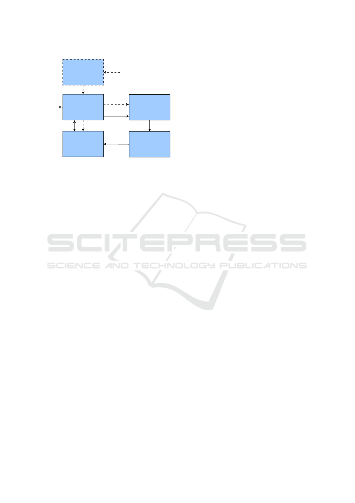
Figure 3: Overview of our approach.
4.1 Overview
In most applications the fuzzer will provide inputs
to a program or function. In the context of plan-
based robotics however, the plan will receive inputs
from its environment. We therefore propose to use
the fuzzer output to generate an environment for the
robot. We divide a robots environment into a static
and a dynamic part. The static part of the environment
is the same for all executions and may e. g. contain
walls or larger pieces of furniture. The dynamic part
should be different between executions and contains
smaller items that are supposed to be manipulated by
the robot.
We use an adapted version of SEECER in com-
bination with CLisp and the fast projection simulator
for the plan execution and libfuzzer for the input gen-
eration. The flow of our program is shown in Figure 3.
It is divided into an initialization phase indicated by
dashed arrows and a main loop indicated by continu-
ous arrows. The steps are numbered according to their
order.
During initialization, the CPL plan (1) is first
parsed and compiled into CLisp bytecode (2). This
bytecode is then analyzed to find all coverage points.
A memory segment is reserved for the respective
counters and given to the fuzzer (3). Finally, the sim-
ulation is initialized and the static part of the environ-
ment is loaded (4).
After the initialization steps are complete, the pro-
cedure enters a main loop that repeats the following
steps. At first the fuzzer provides a byte array as input
to the plan (5). This byte array is then translated into
a set of objects, which are added to the simulation (6).
Afterwards the robotic plan is executed in the simula-
tion environment (7). During execution, the counters
of the chosen coverage metric are updated after ev-
ery instruction. After the execution has finished, the
final state of the simulation is checked for erroneous
behavior such as objects in the wrong location. Any
errors found are reported to the user (8). Addition-
ally, the coverage is updated in the fuzzer (9) and also
reported to the user. Finally, the simulation environ-
ment is reset to prepare for the next iteration.
The main loop can run as long as desired by the
user. Possible stopping criteria include the number of
found errors, a time limit or a coverage limit.
4.2 Initial Environment Setup
Unlike most applications, plan-based robotics require
the fuzzer to provide an initial environment setup in-
stead of an input to a function. In this section we will
cover the translation from generated bytes to this en-
vironment setup in more detail. At first, the environ-
ment needs to be separated into a static and a dynamic
part. Only the dynamic part will change between it-
erations. The static part remains constant throughout
the whole procedure and is therefore independent of
the fuzzer output.
For the dynamic part, objects need to be gener-
ated with several properties such as their type, posi-
tion and orientation. Since not all positions within the
environment may be eligible to create an object at, we
further propose to define regions and reserve part of
the generated bytes to first decide the region and then
the coordinates within that region.
Depending on the number of regions and types as
well as the desired granularity on positions and orien-
tations more than one byte may be necessary to rep-
resent an object. With t possible types, r possible re-
gions, p possible positions per region and o possible
orientations, the number of bytes b should be cho-
sen such that 256
b−1
< tr po ≤ 256
b
, i. e. the smallest
number that will be able to represent all combinations
of type, region, position and orientation.
If the fuzzer produces a total number of bytes that
is not divisible by b, the remaining incomplete object
is discarded.
Example 2. Consider a simple environment with
three tables, which are 90cm by 90cm. In the initial
state, a number of bottles and cups are placed on any
of the tables. The test designer chooses a grid with
a width of 20cm, which results in 4 · 4 = 16 possible
positions per table. The objects will always stand up-
right, but may by turned by multiples of 90 degrees,
resulting in 4 possible orientations. With 2 types, 3
regions, 16 positions and 4 orientations, there are a to-
tal of 384 possible configurations per object and two
bytes will be necessary to represent an object. When
the fuzzer produces 5 bytes, only two objects will be
instantiated and the last byte is discarded.
Coverage-Guided Fuzzing for Plan-Based Robotics
109

Of course, other properties like dimensions, color,
fill level of containers, etc. may be represented in the
same way, when applicable.
4.3 Coverage Measurement
Our approach needs to measure the code coverage to
guide the fuzzer and report it back to the user. In
this section we will describe the instrumentalization
of SEECER and the coverage measurement in detail.
Since SEECER operates on CLisp bytecode, we
will also define our coverage metrics on that byte-
code instead of the higher-level CPL plan. We will
mainly describe the instruction and branch coverage,
but other structural coverage metrics can be added in
a similar manner.
Since libfuzzer requires a counter for each cover-
age point, we will also use this representation inter-
nally. During the initialization phase of our approach,
the bytecode will be analyzed to find the total number
of coverage points. For the instruction coverage this
simply corresponds to the number of executable in-
structions. For the branch coverage, the control flow
instructions, i. e. conditional jumps are counted and
multiplied by two, since there are exactly two out-
comes for each conditional jump. An array of these
counters is created and initialized with zeros.
During execution the counter array is updated us-
ing an observer pattern. Coverage metrics will reg-
ister at the interpreter and in turn the interpreter will
notify them after each instruction execution. The in-
struction coverage metric reacts to all instruction ex-
ecutions and increments the respective counter. The
branch coverage metric only reacts to branching in-
structions and increments one of the two respective
counters depending on whether the branching condi-
tion is true or false.
To measure the total coverage, the number of non-
zero entries in the array is divided by the total number
of entries.
Example 3. Consider the bytecode in Figure 4. The
bytecode is divided into a data section (the unnum-
bered lines at the top) and a code section (the num-
bered lines). The code accesses the data through the
CONST instructions in lines 1, 7 and 11.
The program requires one integer to be present
on the stack. It will then load the first constant, the
numeric value 2 and apply the built-in function 210,
which is the modulo operation (Line 3). The result is
compared to zero (Line 5) and depending on the out-
come the execution will jump to Line 10 or proceed
with Line 7. Ultimately, the program will return ei-
ther "EVEN" or "ODD", depending on the value of the
input.
(CONST 0 ) = 2
(CONST 1 ) = "ODD"
(CONST 2 ) = "EVEN"
1 (CONST 0 ) ; 2
2 (PUSH)
3 ( CALLS2 2 1 0 ) ; MOD
4 (PUSH)
5 ( CALLS2 1 7 2 ) ; ZEROP
6 ( JMPIF L10 )
7 (CONST 1 ) ; "ODD"
8 (PUSH)
9 ( JMP L13 )
10 L10
11 (CONST 2 ) ; "EVEN"
12 (PUSH)
13 L13
14 ( SKIP&RET 1 )
Figure 4: CLisp bytecode example.
For this program, SEECER will initialize a
counter array with 14 entries for the instruction cover-
age, since there are 14 instructions. The counter array
for the branch coverage will have only 2 entries, one
for each possible result of the JMPIF instruction in
Line 6. The JMP instruction in Line 9 does not require
any coverage points, since it is unconditional.
Assume that the program is called with an even in-
put. This will execute Lines 1 to 6 and Lines 10 to 14.
This results in a total of 11 executed instructions and
a instruction coverage of
11
14
≈ 79%. Of the coverage
points for the branch coverage, only the one corre-
sponding to the value true is incremented, resulting in
a branch coverage of 50%.
5 A COVERAGE METRIC FOR
PLAN-BASED ROBOTICS
While general structural coverage metrics like in-
struction or branch coverage have proven their use-
fulness, domain-specific functional metrics are often
able to follow the intended behavior of the program
more closely. Therefore, in this chapter, we introduce
action coverage as a natural functional coverage met-
ric for plan-based robotics. The metric is indepen-
dent of the concrete planning language, but will be
presented and evaluated in the context of CPL in this
paper.
The general idea is to measure which percentage
of the possible actions have been executed by the plan.
Here, not only the type of the action, but all param-
eters are considered. This makes the metric neither
strictly stronger or strictly weaker than the presented
structural coverage metrics. For instance, the same
ICAART 2023 - 15th International Conference on Agents and Artificial Intelligence
110

line of code may execute an action with different pa-
rameters depending on the value of some variable.
The second execution of that line would then increase
the action coverage, but not the instruction or branch
coverage.
If all parameters of the executable actions are dis-
crete and have sufficiently few values, each possible
action parametrization can correspond to a coverage
point. The coverage calculation and implementation
are straight-forward in this case.
Example 4. Consider again the simple environment
from Example 2 with three tables and two object
types. Also consider a two-handed robot acting in this
environment. The robot may pick an object from any
of the tables or place an object on a table. The action
abstracts from the exact position on the table. It is pa-
rameterized by its type (pick or place), the table, the
object type and the arm that is used. This allows for a
total of 2· 3· 2·2 = 24 distinct actions to be performed,
resulting in 24 coverage points.
However, in many cases there will be continuous
parameters or ones with a lot of possible values. In
these cases a straight-forward approach will still work
to some extend, but due to the extremely high or even
infinite amount of possible actions, the overall cov-
erage will be either very close to zero or undefined.
To avoid this problem, we suggest to form buckets
of similar actions and create one coverage point per
bucket.
A bucket is a set of actions that are sufficiently
similar in their parameters. The space of all pos-
sible actions should be divided into a finite set of
buckets such that each action belongs to exactly one
bucket. After an action is executed, the respective
bucket is marked as executed. In our implementation
of coverage-guided fuzzing, each bucket would have
its own counter that is incremented whenever an ac-
tion from that bucket is executed.
The choice of buckets is highly domain-specific
and may depend on the plan and environment under
observation. This obviously makes it harder to com-
pare the quality of different plans acting in different
environments. Still, the comparability of different test
sets for the same plan is preserved and the metric is
well suited to guide a fuzzer.
Example 5. Consider again the environment and ac-
tions from the previous example. Now, assume an ad-
ditional navigation action that will navigate the robot
to a continuous coordinate within the room. This re-
sults in an infinite number of distinct actions. To re-
duce the number of coverage points to a manageable
amount, the navigation action is divided into 4 buck-
ets depending on its target position. There is one
buckets for each table and its surrounding area and
one bucket for all positions not adjacent to a table.
This increases the total number of coverage points to
28.
Action coverage can be used in combination with
coverage-guided fuzzing as presented in the previous
section, but also independently. Like other coverage
metrics it may be used to judge the quality of hand-
written or (semi-)automatically generated test cases.
We believe that action coverage measures the di-
versity of plan executions more closely than structural
coverage metrics, since the focus is on the actual be-
havior of the robot in its environment, and not just on
the control flow of the underlying program.
6 EXPERIMENTAL EVALUATION
This section describes our experimental evaluation.
We evaluate both our approach to coverage-guided
fuzzing for plan-based robotics in general and the
combination with action coverage in particular. In
Section 6.1 we present the plan and environment that
was used for the evaluation. Afterwards, we discuss
our results in Section 6.2.
6.1 Robotic Plan and Environment
We evaluate our approach on a CPL plan that is set
in a warehouse-inspired environment. The static part
consist of a table and a shelf with three boards in a
rectangular room. The dynamic part contains a vari-
able number of objects with three types (milk, cereal
and bowl). Initially, the objects may be on any of the
shelf boards or on the table. The plan is supposed
to sort the objects onto the shelf boards. Each object
type has a corresponding board on the shelf. It does
so by first moving all objects to the table, clearing the
shelf in the process, and then moving them to their re-
spective shelf boards. To save trips between the shelf
and table, the robot will always transport two objects
at once if possible. Due to the width of the shelf, the
robot is not able to reach all positions on it from the
same point. A series of case distinctions is responsi-
ble for picking the right position for the robot to pick
or place both of its objects.
In total, the plan involves 1785 bytecode instruc-
tions, 52 branching instructions and 6 different action
types. These are the move-torso, park-arms, detect-
objects, navigate, pickup and place action.
For the action coverage, we decided on a total of
87 buckets. One bucket belongs to each of the move-
torso, park-arms and detect-objects actions. The nav-
igate action has 6 buckets, which are distinguished
by their target position. The pickup action also has
Coverage-Guided Fuzzing for Plan-Based Robotics
111

6 buckets, depending on the arm and the type of the
object. Finally, the place action is divided into the re-
maining 72 buckets, which are distinguished by the
arm, the type of the object and the target position.
The initial state of the environment is built using
two bytes per object. The first byte decides the type
of the object and one of four regions: the top of the ta-
ble and the top of each of the shelf boards. The second
byte is split in half, with the first four bits correspond-
ing to the relative x position and the last four bits to
the relative y position of the object within the region.
The z position and the orientation are fixed for each
region.
6.2 Experimental Results
In this section we present the results of our experi-
mental evaluation. During execution, we measured
the instruction, branch and action coverage. The
fuzzer is however only able to consider one cover-
age metric at once. Therefore we executed three ver-
sions, with each metric being the guiding metric to the
fuzzer in one version. To achieve a higher consistency
of the results, we executed ten runs per version, for a
total of 30 runs. Each run had a time limit of 5 hours.
We evaluated the following research questions:
• Is coverage-guided fuzzing able to find relevant
errors in robotic plans in a reasonable time?
• How well do the investigated coverage metrics re-
flect a thorough testing of the robotic plan?
• Which effect does the guiding coverage metric
have on the fuzzing process?
• How consistent are the results between runs?
The runs unveiled a total of 7 errors in the plan,
which we categorized by their effect on the final envi-
ronment state.
The shelf edge error occurred when an object in
the initial state was very close to the back edge of the
shelf. This caused it to be occluded by the shelf board.
The robot could therefore not detect the object and
would not move it. This of course caused an invalid
final state, if the object was not initially on its correct
shelf board. Additional positions for the detection of
objects would be necessary to mitigate this error.
In some cases, objects were left on the table, be-
cause they were occluded by other objects and thus
not detected in the second part of the plan. We call
these errors primary table error if the object was
on the table in the initial environment state and sec-
ondary table error if it was moved there. To avoid
this error, the detection and moving objects from the
table should be repeated until the table is empty.
Table 1: Minimum, maximum and average time (in s) to
find each error.
Error min max avg
Primary table 11 89 45
One too high 10 122 57
Two too high 13 315 102
Secondary table 8 528 109
Shelf edge 8 511 169
One too low 125 3348 714
Two too low 411 9517 2336
The final four error categories describe objects
that were sorted onto the wrong shelf board. These
errors stem from either an internal logic error in the
plan or from an inaccurate placing action. Depend-
ing on the difference between the expected and actual
shelf board, we call these errors one too high error,
two too high error, one too low error or two too low
error.
All seven errors were found in all 30 runs, but the
time it took to find each error differed. The minimum,
maximum and average times it took to find each er-
ror are shown in Table 1. The first column contains
the error name, followed by the minimum, maximum
and average time in seconds that it took to find the
respective error. The earliest found errors were the
shelf edge error and the secondary table error, which
were each found after 8 seconds in two different runs.
The error that took the most time to be found was the
two too low error after 9517 seconds (just over 2h and
38min). This strong difference between error types is
also visible in the average times. The two too low
error took over 50 times as much time to be found on
average than the primary table error. But also the time
for each error type differed greatly. This is best seen
with the secondary table error, where the maximum is
66 times as high as the minimum time. The guiding
coverage metric had no clear effect on the time it took
to find errors.
The coverage metrics increased in different ways
during runs, but converged to the same values af-
ter 5 hours for all 30 runs. These values were
97.1% branch coverage, 95.0% instruction coverage
and 59.3% action coverage. Upon further inspection
of the CPL plan these values were found to be the the-
oretical maximum due to a small section of unreach-
able code and several action buckets that could not
be executed by the plan. This also showcases, that
finding suitable buckets is not a trivial problem, since
many parameters of the actions are only decided at
runtime. And while it was no particular priority for
this evaluation, it shows that finding a diverse set of
buckets that still allows 100% action coverage is not
ICAART 2023 - 15th International Conference on Agents and Artificial Intelligence
112

Figure 5: Exemplary coverage development over time.
an easy task.
The amount of time it took to reach those max-
imum values differed greatly between runs. The
branch coverage and instruction coverage always
reached their maximum at the same time, even though
the increases during the runs were not necessarily
synchronous. The fastest time for those two metrics
to reach the maximum was 20 seconds and the slow-
est time 283 seconds. The average time was 98 sec-
onds. The highest action coverage was reached much
slower, with a minimum of 2353 seconds, a maximum
of 13079 seconds and an average of 6802 seconds.
Again, there was no clear effect of the guiding cover-
age metric.
The vastly slower convergence of the action cov-
erage suggests that it is harder to fulfill than the other
two metrics. This also suggests that judging a set of
test cases by their action coverage holds them to a
higher standard than the branch or instruction cover-
age. To undermine this statement, we also looked at
the number of errors that were found only after the
branch, instruction or action coverage had reached
their maximum. The reasoning here is that a maxi-
mum value of some coverage metric should usually
indicate that the test cases cover a high amount of all
possible outcomes and additional errors after that are
unlikely. So if a lot of errors were found after a cov-
erage’s maximum was reached, the coverage is likely
not thorough enough.
Of the 30 total runs, several errors occurred only
after the branch and instruction coverage had reached
their maximum. These were 5 occurrences of the pri-
mary table error, 6 occurrences each of the secondary
table error and the two too high error, 10 occurrences
of the one too high error, 12 occurrences of the shelf
edge error, 25 occurrences of the one too low error
and all 30 occurrences of the two too low error. Only
2 occurrences of the two too low error occurred af-
ter the maximum of the action coverage was reached.
This clearly shows that the branch and instruction
coverage are insufficient for a thorough testing of the
robotic plan, while the action coverage had much bet-
ter outcomes.
Example 6. To visualize the difference between the
metrics, consider Figure 5 that shows the results of
the first run (guided by the instruction coverage). The
y-axis shows the coverage for each metric and the x-
axis shows the time in seconds. To achieve a better
visibility of the results, only the first 1000 seconds of
the run are shown. The blue, orange and green line
show the development of the action, branch and in-
struction coverage, respectively. The red vertical lines
show points at which an error of each category was
found for the first time. The figure shows that the first
four errors were found quickly and before the branch
and instruction coverage had reached their maximum.
The later three errors however were only found after-
wards. All seven errors were found before the action
coverage reached its maximum, which happened out-
side of the scope of the graphic.
With respect to our research questions we can say
that coverage-guided fuzzing was able to find rele-
vant errors in the tested robotic plan. In each run
7 errors were found. This is consistent in terms of
the final result, but not necessarily in terms of the
time needed. The time necessary to find certain er-
rors varied greatly between runs, as can be expected
from a semi-random algorithm. We found that the ac-
tion coverage is a good indicator of the completeness
of a test suite, since in most cases, all errors were
found when it reached its maximum. The instruc-
tion and branch coverage on the other hand did not
work well as an indicator, as almost half of all er-
rors were found after both metrics reached their max-
imum. This quality of the action coverage metric did
however not carry over to its use as a guiding cover-
age metric. There were no clear differences in the be-
havior when a different metric was chosen. Since the
action coverage performed well otherwise, this might
suggest that the chosen fuzzer is simply not very sen-
sitive to the guiding coverage metric. Overall, both
the fuzzing approach and the action coverage have
been successful in our evaluation.
7 CONCLUSION
When autonomous robots act in safety-critical envi-
ronments, the correctness of their high-level plans is
of utmost importance. In this paper, we introduced
coverage guided fuzzing to the domain of plan-based
robotics. We presented our implementation for the
planning language CPL.
Our approach starts with an initialization phase,
Coverage-Guided Fuzzing for Plan-Based Robotics
113

which handles the initialization of the fuzzer and the
simulation as well as the compilation and analysis of
the CPL plan. In the subsequent main loop, the byte
array provided by the fuzzer is translated into an ini-
tial environment setup and the plan is executed in that
environment. During execution, the coverage is mea-
sured and fed back to the fuzzer.
In addition to the fuzzing approach, we presented
a novel coverage metric for the domain of coverage-
guided fuzzing, which measures the percentage of
possible actions that have been performed by the plan.
Our experimental evaluation shows that coverage-
guided fuzzing is able to find relevant bugs in high-
level robotic plans. The novel coverage metric proved
useful in judging the quality of a test suite.
REFERENCES
Böhme, M., Pham, V.-T., Nguyen, M.-D., and Roychoud-
hury, A. (2017). Directed greybox fuzzing. In Pro-
ceedings of the 2017 ACM SIGSAC Conference on
Computer and Communications Security.
Bruns, N., Herdt, V., and Drechsler, R. (2022). Unified
hw/sw coverage: A novel metric to boost coverage-
guided fuzzing for virtual prototype based hw/sw co-
verification. In Forum on Specification & Design Lan-
guages (FDL).
Delgado, R., Campusano, M., and Bergel, A. (2021). Fuzz
testing in behavior-based robotics. In 2021 IEEE In-
ternational Conference on Robotics and Automation
(ICRA).
Fioraldi, A., D’Elia, D. C., and Querzoni, L. (2020).
Fuzzing binaries for memory safety errors with qasan.
In 2020 IEEE Secure Development (SecDev).
Gorbunov, S. and Rosenbloom, A. (2012). Autofuzz: Au-
tomated network protocol fuzzing framework. In IJC-
SNS International Journal of Computer Science and
Network Security.
Haible, B., Stoll, M., and Steingold, S. (2010). Implemen-
tation notes for gnu clisp.
Kim, H., Ozmen, M. O., Bianchi, A., Celik, Z. B., and Xu,
D. (2021). Pgfuzz: Policy-guided fuzzing for robotic
vehicles. In Network and Distributed System Security
Symposium (NDSS).
Li, J., Zhao, B., and Zhang, C. (2018). Fuzzing: a survey.
Cybersecurity.
llvm (2022). libfuzzer – a library for coverage-guided
fuzz testing. https://llvm.org/docs/LibFuzzer.html,
Accessed on: 6th Oct 2022.
Luckcuck, M., Farrell, M., Dennis, L. A., Dixon, C., and
Fisher, M. (2019). Formal specification and verifica-
tion of autonomous robotic systems: A survey.
Meywerk, T., Walter, M., Herdt, V., Große, D., and Drech-
sler, R. (2019). Towards Formal Verification of Plans
for Cognition-enabled Autonomous Robotic Agents.
In Euromicro Conference on Digital System Design
(DSD).
Miller, B. P., Fredriksen, L., and So, B. (1990). An empiri-
cal study of the reliability of unix utilities. Commun.
ACM.
Mösenlechner, L. and Beetz, M. (2013). Fast temporal pro-
jection using accurate physics-based geometric rea-
soning. In 2013 IEEE International Conference on
Robotics and Automation.
Rawat, S., Jain, V., Kumar, A., Cojocar, L., Giuffrida, C.,
and Bos, H. (2017). Vuzzer: Application-aware evo-
lutionary fuzzing. In NDSS Symposium 2017.
Woodlief, T., Elbaum, S., and Sullivan, K. (2021). Fuzzing
mobile robot environments for fast automated crash
detection. In 2021 IEEE International Conference on
Robotics and Automation (ICRA).
Zalewski, M. (2017). Technical "whitepaper" for
afl-fuzz. https://lcamtuf.coredump.cx/afl/technical_
details.txt, Accessed on: 6th Oct 2022.
ICAART 2023 - 15th International Conference on Agents and Artificial Intelligence
114
