
Stereoscopy in User: VR Interaction
Błażej Zyglarski
a
, Gabriela Ciesielska
2b
, Albert Łukasik
2c
and Michał Joachimiak
3d
1
Faculty of Mathematics and Computer Science, Nicolaus Copernicus University in Torun, Torun, Poland
2
Vobacom sp. z o.o. in Torun, Torun, Poland
3
Faculty of Physics, Astronomy and Informatics, Nicolaus Copernicus University in Torun, Torun, Poland
Keywords: Stereoscopy Reconstruction, Cloud Point 3 Reconstruction.
Abstract: Viewing experience is almost natural since the surroundings are real and only the augmented part of reality
is displayed on the semi-transparent screens. We try to reconstruct stereoscopy video with use of a single
smartphone camera and a depth map captured by a LIDAR sensor. We show that reconstruction is possible,
but is not ready for production usage, mainly due to the limits of current smartphone LIDAR implementations.
1 INTRODUCTION
Augmented Reality is modern subject, implemented
by many companies, in fields of entertainment,
business and education. The most significant issue is
that top Augmented Reality Devices are very
expensive and despite of offering extraordinary
quality, can’t be used widely.
Best of AR devices offer holographic screens or
provide extraordinary immersion with use of
stereoscopic cameras (eg. Microsoft HoloLens).
Therefore, viewing experience is almost natural since
the surroundings are real and only the augmented part
of reality is displayed on the semi-transparent
screens. The “cheap” way is “cardboard-like”
headset, which allows you to use your smartphone as
a screen. However most smartphones have mono -
camera module placed with no chance to achieve
stereoscopic view for your eyes.
We present a method to reconstruct stereoscopic
view with current LIDAR-equipped phones and
discuss it.
2 AUGMENTED REALITY
DEVICES
In augmented reality there are two cases of
stereoscopic video for the AR space. By stereoscopic
video it is meant that the different background images
a
https://orcid.org/0000-0002-1822-2467
b
https://orcid.org/0000-0001-7320-8636
are correctly displayed for each eye. We can
distinguish devices with physical stereoscopic view
as in Microsoft HoloLens devices; physical cameras
converting to stereoscopic digital view as in Pico Neo
3; And digital reconstruction of surround-dings with
the usage of a smartphone with a single camera
In third case, it is necessary to consider the possible
ways of 3D perception and possibly find a way to
reconstruct the image, which is in the basic case limited
to the display picture captured by the chosen camera
and duplicate it for both eyes. 3D perception is a skill
developed by the human brain from a series of inputs.
The basic, but
not the only one, is the stereoscopic
image from both eyes (most predators have stereo
vision (Yang & Zhang, 2020). In the basic solution,
this is not even close to perfect 3D perception.
2.1 3D Reconstruction
Modern smartphones use multiple cameras (thus they
are still too close to each other when it comes to
reproducing a 3D impression) and depth sensors
(LIDAR) to produce depth data of the image used
then in multiple “Augmented” reality apps. Having
such data stream, we succeeded to produce
stereoscopy reconstruction of captured image on the
reference device and check possibility of its market
use. The reference device on which the algorithms
were tested is the iPhone 13 Pro (Max) with a LIDAR
sensor and 3 cameras, from which the depth map is
created.
c
https://orcid.org/0000-0001-7283-7999
d
https://orcid.org/0000-0002-4462-2376
Zyglarski, B., Ciesielska, G., Łukasik, A. and Joachimiak, M.
Stereoscopy in User: VR Interaction.
DOI: 10.5220/0011617300003417
In Proceedings of the 18th International Joint Conference on Computer Vision, Imaging and Computer Graphics Theory and Applications (VISIGRAPP 2023) - Volume 2: HUCAPP, pages
137-142
ISBN: 978-989-758-634-7; ISSN: 2184-4321
Copyright
c
2023 by SCITEPRESS – Science and Technology Publications, Lda. Under CC license (CC BY-NC-ND 4.0)
137
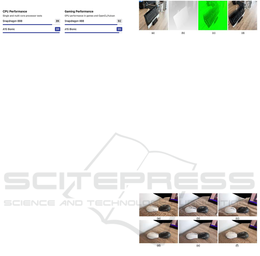
Table 1: Performance comparison.
In addition, the device uses the A15 Bionic
processor, which is characterized by higher
performance than flagship devices from the Android
market (Table 1) and has 6 graphic cores for which
the above-mentioned algorithms are optimized.
3 3D RECONSTRUCTION
ALGORITHMS
Our goal is to explore solutions for achieving
stereoscopy vision with use of smartphone device and
cardboard-type headset.
3.1 Research Steps
Research steps we have taken: 1) Development of
algorithms based on the depth map allowing to create
at least 2,5-dimentional stereoscopic scene; 2)
Checking algorithms possible efficiency and
comparing them; 3) Evaluating better algorithm
against source material; 4) Testing algorithms in
native implementations and performance analysis; 5)
Recommendation to use the algorithm in production
software.
3.2 Developed algorithms
We have prepared two algorithms, which use depth
cloud. A) Full 3D reconstruction using spatial point
cloud, which assumes generating a 3D space based on
a live depth map and displaying it as a 3D scene -
generating a view for the right and left eye based on
the orientation of the camera in space; and B) 2,5D
Reconstruction with cutting out layers and blending
them into adjusted 2D Image, with use of appropriate
parallax.
Both algorithms had potential, but only algorithm
A was efficient enough (on-devi ce) to use it in test
case stage, and due to that is the main subject of this
article.
3.2.1 Cloud Point 3D Reconstruction
Algorithm
The algorithm is based on the reconstruction of the
point cloud in 3D space based on live data from the
LIDAR sensor.
Figure 1: Steps of image analysis: (a) Texture taken from
the phone camera, (b) Data from the depth sensor (LIDAR)
(c) 3D scene generated on the basis of the depth sensor data
(d) Scene with texture overlaid.
Reconstruction steps (as shown on Fig. 4) are: (a)
texture data being acquired from the camera; (b)
depth data being acquired from the LIDAR sensor; (c)
construction of a 3D scene based on the depth map
and filling missing parts (with resolution
extrapolation); (d) Texturing of scene elements. The
key stage is to complete the missing elements of the
scene. The missing points are caused by the low
resolution of the cloud and the shift of the point from
which the virtual camera is looking (to generate a 3D
view). ARKit depth mapping creates a low-resolution
map. The Metal Framework has Shader (MPS)
implementations that allow you to fill in the holes. In
the tested case, a supplement taking the edge into
account in the image analysis (MPSGuidedFilter) was
used. The results are shown in Fig 2. (f) without
upsampling, (a-e) with different parameters (kernel
diameter - window size for algorithm (1-5), epsilon)
Figure 2: Using a GuidedFilter to increase the resolution of
a depth map.
Guided Filter Algorithm for Resolution Upscaling
Guided Filter ("Guided filter", 2022) is a type of
edge-preserving smoothing filter. It can filter out
noise and texture or allow you to increase the
resolution while keeping the edges sharp. Unlike the
Bilateral filter ("Bilateral filter", 2022) this filter does
not use calculations with linear computational
complexity. The Guided Filter (Apple Developer
Documentation, n.d.) can also be used to segment the
image, allowing you to increase the cut quality while
preserving the actual edges (Fig. 3).
HUCAPP 2023 - 7th International Conference on Human Computer Interaction Theory and Applications
138
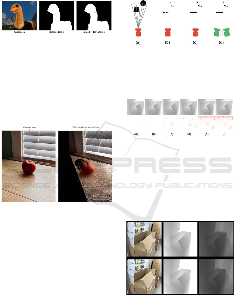
Figure 3: Use of Guided Filter for edge enhancement in the
image segmentation process (He, Sun & Tang, 2012).
Guided Filter is implemented natively in well-
known image processing libraries, including OpenCV
and iOS graphics libraries (MPSGuidedFilter).
Data Processed by the Guided Filter
The data from the depth camera, processed with the
GuidedFilter algorithm, is used as the source for the
3D scene. An object is generated in the space based
on the color of each pixel. Its distance from the
camera is determined by the color of the pixel on the
depth map.
Figure 4: A 3D scene generated from the depth map,
without resolution upscaling (Apple Developer
Documentation, n.d.).
Scene Generation
Scene generation algorithm works as following:
1) For each point on the depth map, its position on
the stage in relation to the camera (x, y) is
calculated
2) Along with the depth data (color on the depth
map), the position (x, y, z) is calculated where z is
the distance from the camera
3) Based on the point position, the pixel color is
sampled from the original image.
The scene is done using two cameras that simulate
the distance between the eyes
Figure 5: Rendering process (a) LIDAR depth mesh (b)
detected points (c) points after processing with an algorithm
increasing the resolution (d) camera viewpoints during
rendering of the resulting view.
The input data from the depth sensor is quite
variable. When observing a static image, we can notice
differences in the consecutive collected frames (Fig 9).
Figure 6: Differences in collected image frames.
They are especially visible at the edges. While it is
not a problem in embedding objects in a 3D scene,
because the ARKit/ARCore algorithms focus on
surface recognition, then in the case of attempts to
reconstruct the entire scene in a 3D form, they cause
flickering edges. Attempting to reduce flicker by
stacking the few of the last few frames (Fig 7.,
algorithm based on hardware image filter acceleration
CoreImage) allows for greater stability with a still
image but increases edge flickering during camera
movement.
Figure 7: Stacking following frames.
At the same time, the readings for flat surfaces also
change over time.
Stereoscopy in User: VR Interaction
139
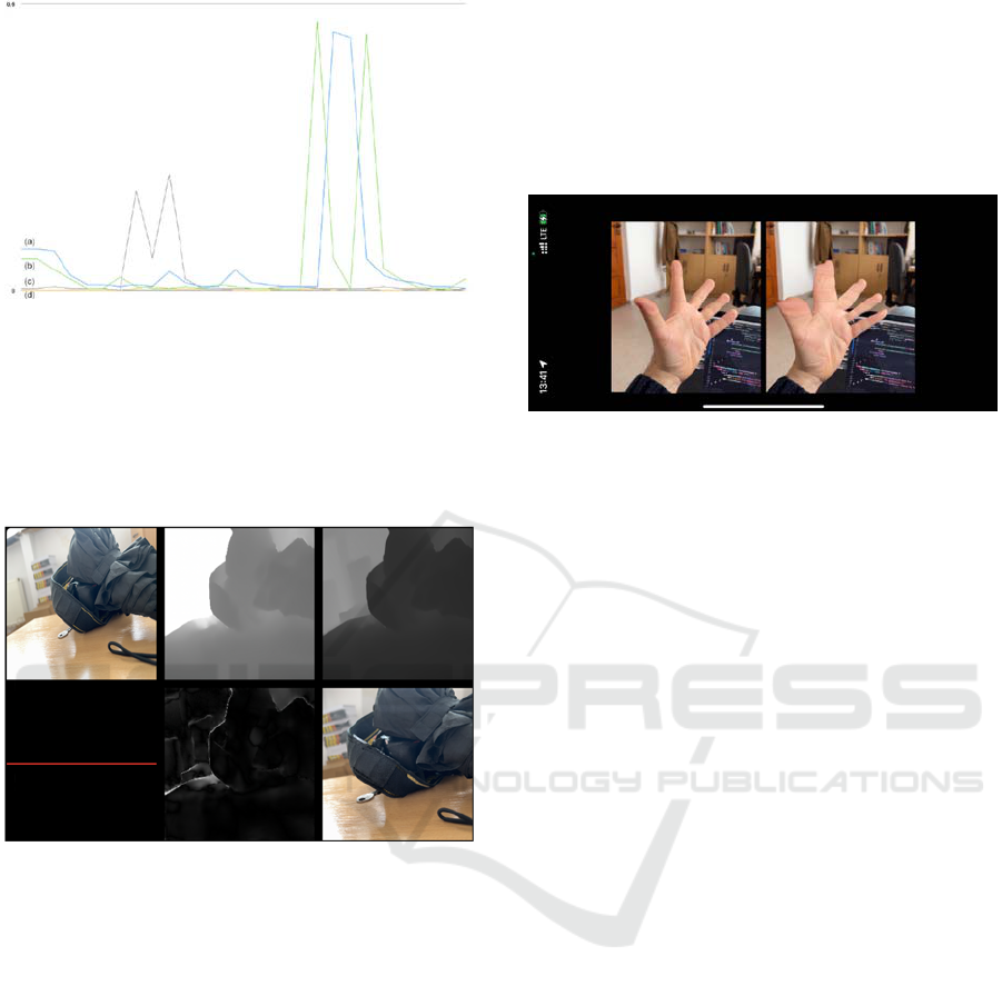
Graph 1: (a,b) High glossy surfaces flickering, (c,d) Non-
glossy surfaces flickering.
Graph 1. shows examples of changes between
individual frames (the average difference in the
brightness of pixels on the depth map) for static views
of objects with shiny surfaces (1,2) and without shiny
surfaces (3,4).
Figure 8: View of an exemplary glossy surface.
The most important problem for shiny surfaces and
edges is changing the pixel depth with each reading,
causing the edges and shiny planes to vibrate. Part of
the problem can be eliminated by averaging the
frames taken from the LIDAR sensor (which, as the
matter of fact, is already done by hardware
preprocessing). Second problem is the lack of
knowledge about pixels hidden behind edges when
generating a 3D view for the other eye. The problem
can be partially mitigated by the algorithms built into
ARKit. However, the result is not ideal – it generates
artifacts for objects located close to it, so in particular
it will concern the issue of controlling and displaying
controllers or hands.
Close Scene Generation Results
We developed an algorithm, which allowed us to
generate scenes with few parameters toggled as
“upsampling” and “stacking frames”. We have
displayed generated video for each eye. For better
quality left eye virtual camera was placed as original
camera (since original camera of the smartphone
while wearing a cardboard set is nearly in front of left
eye). Right eye view was generated from “virtual
point of view” moved about 5 cm right (Fig 9).
Figure 9: Upsampling and edge enhancement by frames
stacking.
Results were poor, especially for close objects.
Averaging the pixels on the edges gives objects extra
depth as the edge readings are very imprecise.
Increasing the resolution of the LIDAR sensor will
allow the use of a 3D image generation tool in the
future. However, at this stage, the results are not
satisfactory.
Inpainting Ideas
Artifacts mainly concern places where the algorithm
cannot correctly calculate the distance. Tests have
shown that such problems are visible on all reflective
surfaces, transparent, with high detail, which is
greater than the LIDAR resolution and of
course we
don't have enough data everywhere. In this
case the
best solution would be to use an inpainting
algorithm
filling all the gaps, but this is not the case in the
“mobile” type of algorithm. All known inpainting
algorithms use large datasets and are heavy loaded,
unsuitable for mobile devices. Regardless of the
performance results of current devices, it can be
assumed that in the upcoming years more efficient
smartphones will appear on the market, allowing for
the use of an additional step for each layer
(inpainting).
Large Scene Results
Regardless poor results in close scenes, other thing is
our large and mid-range scene results, which were
more than good. Example scenes are presented in Fig
10.
HUCAPP 2023 - 7th International Conference on Human Computer Interaction Theory and Applications
140

Figure 10: Mid-range scene.
It turns out, that missing edges data in mid- and far-
range scenes can be easily simulated with Guided
Filter and with big enough resolution those additions
can be missed out by scene viewer.
4 ALGORITHM EVALUATION
Out of the two tested algorithms, an algorithm based
on generating 3D space from a point cloud based on
data collected from the LIDAR sensor was selected.
Figure 11: Device setup.
The algorithm was run on a reference device and a
test video was recorded, which was later used as a
survey material for the survey participants. The test
material is therefore a generated stereoscopic video.
The test material was compared with the reference
material recorded with two identical devices to obtain
a full-fledged stereoscopic video.
Test videos were recorded with three reference
devices set (Fig. 11). The devices were placed on
parallel stands to ensure their correct positioning. To
simplify the research process, it was assumed at this
stage that the reference cameras would be positioned
parallel to each other, with an appropriate shift, which
would allow the human eye to recognize 3D space
("Simple Stereo Camera Calibration", 2021).
4.1 Test Set
Figure 12: Regenerated stereoscopic video.
Twenty test sequences have been recorded. The test
sequence consisted of a 30-second recording made
with two cameras and is a full-fledged stereoscopic
video or
30-second video made
with one camera
using 3D reproduction to generate the image of the
other camera. The recordings were prepared in
various test conditions, in which use seems likely due
to the specificity of the solution being developed.
For example, it was desk view in medium-sized
office or open space (Fig. 12).
4.2 Test Survey
Each sequence was displayed to study participants
using CardBoard tools and reference smartphones.
After each sequence, the user filled in the
questionnaire.
The sequences were rated on a scale of 1 to 5 in the
following categories each:
On a scale of 1 to 5, determine how high you
think the quality of the 3D image was
To what scale did 3D video cause discomfort
(1-small, 5-large)
Did the 3D image feel natural?
Was the 3D scale impression correct?
Was the sense of distance correct?
4.3 Survey Results
Survey results was in every question better for
reference real 3D stereoscopic video.
Stereoscopy in User: VR Interaction
141
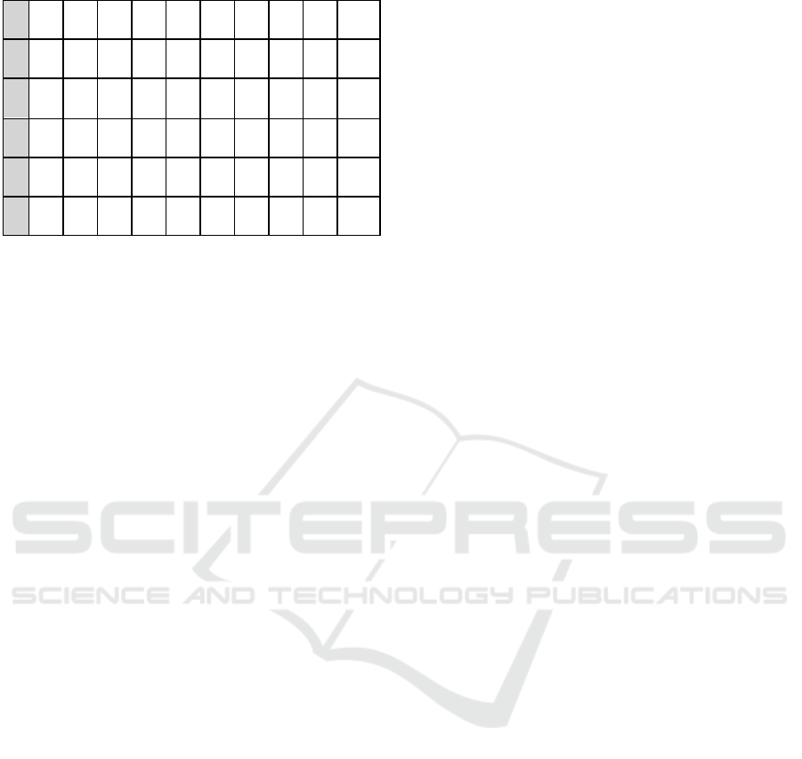
Table 3: Average survey results.
M1 M2 M3 M4 M5 M6 M7 M8 M9 M10
Q1 3,0 2,4 4,0 2,4 3,6 2,7 4,0 3,0 3,4 2,6
Q2 2,0 3,4 1,6 2,9 1,7 2,6 1,7 2,4 1,6 2,9
Q3 3,4 2,6 4,0 2,6 4,0 2,7 3,9 3,3 4,1 2,4
Q4 3,7 3,1 4,0 3,0 4,0 2,7 4,0 3,7 3,7 3,4
Q5 3,7 3,7 4,0 3,1 3,6 3,4 4,6 4,0 4,1 3,6
It is especially visible in the quality survey question
(Q1), where better quality in real video is caused by
the low resolution of regenerated cloud space. All
respondents stated that generated video caused some
discomfort and didn’t feel natural, which is also
connected to low resolution. Better results were
achieved in scale and distance tests, where
respondents stated that impression of those was better
than average. Moreover, survey results were similar
in generated and real stereoscopic video.
5 CONCLUSIONS
Considering the lack of inpainting (which is a non-
trivial task) and intelligent layer division (also non-
trivial) in the above test, the achieved results are
strongly insufficient for commercial implementation.
In the case considered in this study, inpainting would
have to be carried out in a quite complex range for
each layer of the generated image, several dozen
times per second (minimum 25, preferably around
60). This is a criterion that effectively excludes the
use of this type of solution in the current state of the
art. However, we recommend returning to the
analysis of this task within the time frame of several
years.
ACKNOWLEDGEMENTS
This paper was created as a part of the EU project
“Development of a novel training ecosystem using
mixed reality (MR) technology”. The project is co-
financed by the European Regional Development
Fund under Priority Axis 1 Support for R&D by
enterprises, Measure 1.1. R&D projects of
enterprises, Sub-measure 1.1.1 Industrial research
and development works carried out by enterprises,
Intelligent Development Operational Program 2014-
2020.
REFERENCES
Apple Developer Documentation. (n.d.). Retrieved October
5, 2022, from https://developer.apple.com/
documentation/avfoundation/additional_data_capture/
capturing_photos_with_depth
Bilateral filter. (2022). In Wikipedia. Retrieved October 5,
2022, from https://en.wikipedia.org/wiki/Bilateral
_filter
Chan, T., Shen, J. (2000). Mathematical models for local
deterministic inpaintings. UCLA CAM TR, 00-11.
Faugueras, O. D., Toscani, G. (1989). The calibration
problem for stereoscopic vision. In Sensor devices and
systems for robotics (pp. 195-213). Springer, Berlin,
Heidelberg.
First Principles of Computer Vision. (2021). Simple Stereo
| Camera Calibration [Video]. YouTube. Retrieved
October 4, 2022, from https://www.youtube.com/
watch?v=hUVyDabn1Mg
Guided filter. (2022). In Wikipedia. Retrieved October 5,
2022, from https://en.wikipedia.org/wiki/Guided_filter
Heeger, D. J., Bergen, J. R. (1995). Pyramid-based texture
analysis/synthesis. In Proceedings of the 22nd annual
conference on Computer graphics and interactive
techniques (pp. 229-238).
He, K., Sun, J., & Tang, X. (2012). Guided image filtering.
IEEE transactions on pattern analysis and machine
intelligence, 35(6), 1397-1409.
Kim, J. H., Yun, Y., Kim, J., Yun, K., Cheong, W. S., &
Kang, S. J. (2019). Accurate camera calibration method
for multiview stereoscopic image acquisition. Journal
of Broadcast Engineering, 24(6), 919-927.
Köhler, R., Schuler, C., Schölkopf, B., & Harmeling, S.
(2014). Mask-specific inpainting with deep neural
networks. In German conference on pattern recognition
(pp. 523-534). Springer, Cham.
Raajan, N. R., Philomina, B. M. A. J., Parthiban, D., &
Priya, M. V. (2012). Camera calibration for
stereoscopic technique. In IEEE-International
Conference on Advances in Engineering, Science And
Management (ICAESM-2012) (pp. 582-585). IEEE.
Tschumperlé, D., & Deriche, R. (2005). Vector-valued
image regularization with
PDEs: A common framework for different applications.
IEEE transactions on pattern analysis and machine
intelligence, 27(4), 506-517.
Venkatesh, M. V., Cheung, S. C. S., & Zhao, J. (2009).
Efficient object-based video inpainting. Pattern
Recognition Letters, 30(2), 168-179.
Yang, H., & Zhang, Z. (2020). Depth image upsampling
based on guided filter with low gradient minimization.
The Visual Computer, 36(7), 1411-1422.
HUCAPP 2023 - 7th International Conference on Human Computer Interaction Theory and Applications
142
