
Flexible Extrinsic Structured Light Calibration Using Circles
Robert Fischer
1
, Michael H
¨
odlmoser
2
and Margrit Gelautz
1 a
1
Visual Computing and Human-Centered Technology, TU Wien, Vienna, Austria
2
emotion3D GmbH, Vienna, Austria
fi
Keywords:
Device Calibration, Structured Light Calibration, Stereo Camera.
Abstract:
We introduce a novel structured light extrinsic calibration framework that emphasizes calibration flexibility
while maintaining satisfactory accuracy. The proposed method facilitates extrinsic calibration by projecting
circles into non-planar and dynamically changing scenes over multiple distances without relying on the struc-
tured light’s intrinsics. Our approach relies on extracting depth information using stereo-cameras. The imple-
mentation reconstructs light-rays by detecting the center of circles and reconstructing their 3D-positions using
triangulation. We evaluate our method by using synthetically rendered images under relevant lighting- and
scene conditions, including detection drop-out, circle-center detection error, impact of distances and impact
of different scenes. Our implementation achieves a rotational accuracy of below 1 degree and a translational
accuracy of approximately 1 cm. Based on our experimental results we expect our approach to be applicable
for use cases in which more flexible extrinsic structured light calibration techniques are required, such as au-
tomotive headlight calibration.
1 INTRODUCTION
The process of registering the position and orientation
of a camera or projector relative to another camera
is called extrinsic calibration. It is a common task
in computer vision, whose main application fields
cover robotics, automotive scenarios, and virtual real-
ity. Our work focuses on the calibration of a projector
in relation to a stereo-camera, also known as a dual-
camera structured light system (Chen et al., 2018)
(An et al., 2016) (Zhang and Yau, 2008). In gen-
eral, our approach is applicable to different use cases
and scenarios, such as surveillance, stage-productions
or other sensor-supported smart lighting applications
(Sonam and Harshit, 2019) (Gillette and McNamara,
2020). In particular, we apply our method to the cal-
ibration of headlights of cars, allowing the develop-
ment of programmable automotive headlights (Tam-
buro et al., 2014). Such a system illuminates spe-
cific regions of interest, which could be extracted us-
ing different sensors (e.g. camera, LIDAR sensor,
etc.). In order to transform such regions of interest
(e.g. road signs, pedestrians, etc.) from the sensor co-
ordinate system into the projector coordinate system,
an extrinsic calibration of the projector relative to the
sensor has to be available.
a
https://orcid.org/0000-0002-9476-0865
In general, current state-of-the-art approaches for
projector extrinsic calibration are limited in terms of
flexibility. In particular, they usually assume a pla-
nar projection target at a relatively close distance to
the projector (Garrido-Jurado et al., 2016) (Huang
et al., 2018) (Chen et al., 2016). This limits the ap-
plicability of extrinsically calibrating a projector in
non-controlled environments, particularly where non-
planar projection surfaces are predominant, or envi-
ronments in which the calibration must be performed
over a large range of distances. Hence, the design of
our structured light calibration approach is motivated
by the following challenges:
• Support of non-planar calibration targets: In cer-
tain situations it is necessary to calibrate a struc-
tured light system in a non-controlled environ-
ment, where the availability of a regular planar
calibration target cannot be assumed.
• Support of dynamically changing scenes: Sim-
ilarly, non-controlled environments may change
during calibration.
• Independent of structured light intrinsics: In gen-
eral, in order to estimate the extrinsics of a struc-
tured light, homography-based approaches rely on
the intrinsics of the structured light (Zhang, 2000).
Our approach does not require the intrinsics of the
structured light device to be known.
Fischer, R., Hödlmoser, M. and Gelautz, M.
Flexible Extr insic Structured Light Calibration Using Circles.
DOI: 10.5220/0011614500003417
In Proceedings of the 18th Inter national Joint Conference on Computer Vision, Imaging and Computer Graphics Theory and Applications (VISIGRAPP 2023) - Volume 4: VISAPP, pages
47-55
ISBN: 978-989-758-634-7; ISSN: 2184-4321
Copyright
c
2023 by SCITEPRESS – Science and Technology Publications, Lda. Under CC license (CC BY-NC-ND 4.0)
47
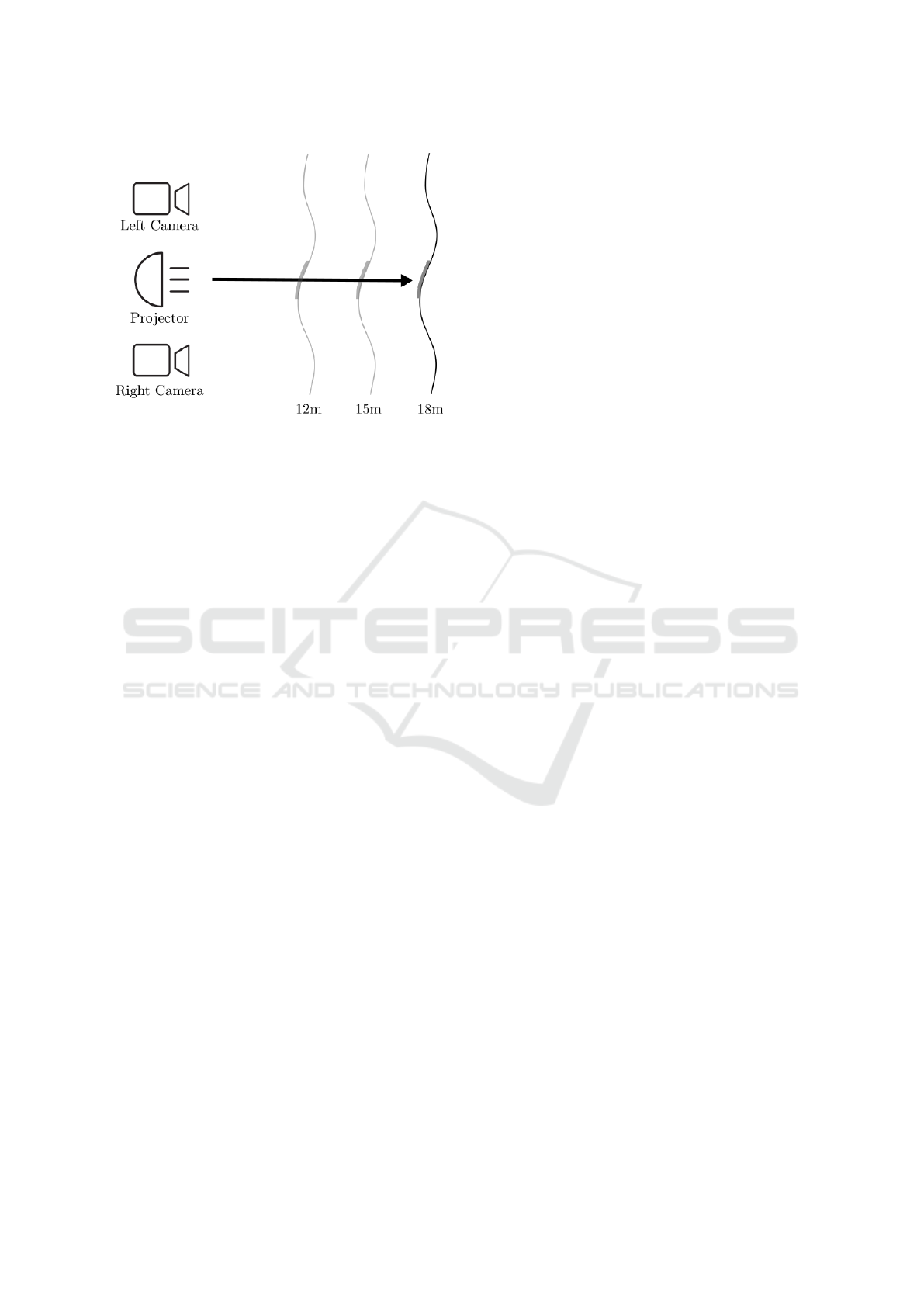
Figure 1: Schematic overview of the calibration setup for
a single ray. Note that our approach supports non-planar
target projection surfaces, as long as the circle detector can
detect the centers of the circles reliably.
Our method projects circles sequentially onto var-
ious non-planar projection surfaces within a scene,
which are located at different relative distances from
the camera center. The circles are detected in both
the left and the right images of the stereo camera and
the 3D positions of the circles are triangulated. By
identifying multiple such circles and their centers in
3D, projection rays going through the centers can be
defined and the extrinsics between the stereo camera
and the projector can be calculated using the inter-
section of all these rays. Our approach works with a
wide range of different projection surfaces. The only
prerequisite is that circles can be detected. Hence,
the calibration can be done automatically, which al-
lows re-calibration during operation (e.g. because of
misalignment over time due to vibrations, etc.). In
contrast to the extrinsics, the intrinsics of a struc-
tured light system are static and usually require less
frequent re-calibration. Figure 1 shows a schematic
overview of the projector and camera setup we use for
our approach. It consists of two time-synchronized
cameras with known camera parameters (both intrin-
sic and extrinsic parameters) and a projector capa-
ble of projecting a monochrome circle pattern into
the scene. Our method provides a calibration accu-
racy sufficient for intelligent lighting systems (Tam-
buro et al., 2014) or applications with similar pre-
cision, such as smart lighting installations (Sonam
and Harshit, 2019) and stage-productions (Gillette
and McNamara, 2020). More precisely, we aim for
a translational error in the range of 1 cm (or less) and
a rotational error of not more than 1 degree. Contrary
to alternative solutions, our method projects a simple
circular calibration pattern into a variety of possible
scenes, allowing calibration over a wide range of dis-
tances and also with different projector types.
2 RELATED WORK
Most previous methods for calibration of a stereo-
camera structured light system involve the projection
of more complex patterns (often fringe patterns) into
the scene, while also expecting a controlled environ-
ment (Zhang and Yau, 2008) (Chen et al., 2016).
(Chen et al., 2018) propose to simplify structured
light calibration by reducing the amount of projected
images. (Garrido-Jurado et al., 2016) generalize to
simultaneously reconstruct and calibrate structured
light systems. Some methods focus on calibration
with a single camera (Huang et al., 2018) (Shah-
paski et al., 2017). Other structured light extrinsic
calibration approaches are based on the homographic
extrinsic calibration approach proposed by (Zhang,
2000). One problem associated with projecting rel-
atively complicated patterns into the scene is that cal-
ibration becomes challenging over larger distances or
in non-controlled environments (An et al., 2016), as
in these cases the higher frequency details (such as
lines and gradients) are challenging to detect.
Multi-Camera Structured Light Systems: In order
to estimate the calibration of a structured light sys-
tem, (Chen et al., 2018) propose to project fringe im-
ages into the scene and apply a variant iterative clos-
est point algorithm. Earlier work of (Chen et al.,
2016) also applies circles for calibration, they use
(Zhang, 2000) for the intrinsic calibration of the pro-
jector. (Zhang and Yau, 2008) propose to use ab-
solute phase-assisted three-dimensional data for reg-
istration of a dual-camera structured light system.
Their approach also requires the projection of rather
complicated fringe images into the scene. Similarly,
(Garrido-Jurado et al., 2016) also project a relatively
complicated image pattern into the scene.
Single-Camera Structured Light Systems: There
are also various works on single camera structured
light system calibration. Notably, (Huang et al., 2018)
propose a single-shot-per-pose approach which han-
dles imperfect planar targets, again, assuming a pla-
nar target and also projecting a more complicated pat-
tern into the scene. (Shahpaski et al., 2017) perform
a radiometric and a geometric calibration simultane-
ously, again relying on projecting a relatively com-
plex calibration pattern into the scene, while also as-
suming a planar projection target. (An et al., 2016)
propose a method for long-range structured light sys-
tem calibration. However, their approach projects a
relatively complex calibration pattern into the scene
VISAPP 2023 - 18th International Conference on Computer Vision Theory and Applications
48

Figure 2: Sample pattern used for calibration, from which
one circle per calibration step is projected. Circles I and II
are used to estimate the projector’s rotation.
and assumes a planar projection target. Thus, their
approach is not applicable to the distances and scenes
our approach is able to operate in.
3 METHOD
In the following subsections, we discuss the struc-
tured light calibration method in more detail. In Sub-
section 3.1 we provide the requirements regarding the
hardware set-up of our proposed method. In Subsec-
tion 3.2 we explain the algorithm of our method both
in form of a textual description and pseudo-code.
3.1 Hardware Set-Up
Our calibration technique estimates both the rotation
and translation of a projector relative to the coordinate
system defined by the stereo camera. Our method is
comprised of two main hardware components: (1) A
stereo camera with two time-synchronized cameras
and known camera parameters (both intrinsics and ex-
trinsics) and (2) a projector. Instead of using stereo
cameras, other camera systems (e.g.: RGB-D) can
also be used, as long as a depth estimation for selected
pixels of the projected pattern can be computed. The
projector must be capable of projecting individual cir-
cles into the scene (Figure 2). In order to perform
the extrinsic calibration of the projector, the circles of
the calibration pattern must be detectable using visual
cues. Refer to Section 4 for a more detailed evaluation
of the associated constraints of our approach.
3.2 Algorithm
In the following, we describe the algorithm for esti-
mating the projector’s extrinsics. Algorithm 1 shows
the corresponding pseudo-code.
Step 1: The projector sequentially projects the circles
from the calibration pattern into the scene (Figure 2).
The circles are relatively easy to project using digital
light processing (DLP) (Packer et al., 2001). Even
a sequence of simple circular stencils in front of the
light source could be sufficient. Refer to Figure 1 for
a schematic overview of the setup.
Step 2: Then, the stereo camera captures a frame of
the projected circle in the scene. Ideally, the projec-
tion of the circle is fully visible in both cameras, as
this simplifies the circle center detection of step 3.
Figure 3 shows a typical example of a captured stereo
image. In practice, there will typically be some occlu-
sions present (e.g.: occlusion with the floor), which
may hinder the reliable detection of the calibration
circles. Surfaces with high reflectivity (mirrors) or
very diffuse projection surfaces might make reliable
circle detection more challenging as well.
Step 3: Our algorithm detects the circles in both
stereo camera views using the expected calibration
pattern template and assigns a correspondence be-
tween the template and the detected pattern. To ease
correspondence detection and avoid mismatching cir-
cle projections, we project a single circle at a time.
For simpler scenes, the circles can be detected us-
ing Hough transformations, while for more compli-
cated scenes a Convolutional Neural Network (Red-
mon et al., 2016) might be more appropriate. To avoid
the necessity of finding correspondences for multi-
ple detected circles, we project exactly one circle per
frame into the scene.
Step 4: Triangulation of the center positions of the
detected circles from the stereo images results in a
3D position representing the circle’s center position
relative to the stereo camera. For RGB-D camera se-
tups, this triangulation step can be skipped, as the Z
component of the point is already known.
Step 5: Repeat steps 1 - 4 for several relative dis-
tances. We measure the relative distance from the
projector’s lens to the projection target in a straight
line. Principally, the more of these relative distances
per calibration circle are captured, the more accurate
the estimation of the extrinsics will be. In the next
step, we use the extracted 3D points to construct rays,
hence at least two points per calibration circle (Fig-
ure 2) are required to construct a ray. In general,
the combination of different calibration distances in-
creases the accuracy of the extrinsic calibration re-
sults. The decrease in accuracy with fewer calibration
distances can be attributed mainly to the inherent in-
accuracy of the 3D triangulation of the circle center
points of the projected calibration pattern. In Sec-
tion 4.6 we evaluate the impact of different distance
configurations and in Section 4.7 we evaluate the im-
pact of different target projection surfaces.
Flexible Extrinsic Structured Light Calibration Using Circles
49
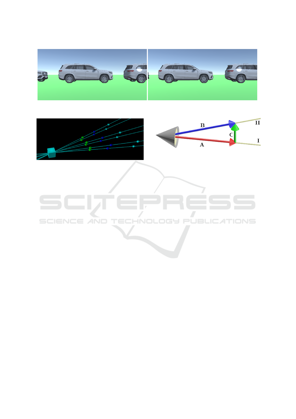
Figure 3: Stereo images (left and right camera) from the car parking scene. Depicts how non-planarity affects the projection
of circles into the scene. Resulting calibration evaluated in Section 4.7.
Figure 4: Visualization of the ray intersections using the tri-
angulated 3D points. The projector is placed with increas-
ing distance to the projection surface. The green points have
a distance of roughly 5m, the blue points 8m and the cyan
points 13m relative to the projector. Figure 2 shows the vis-
ible parts of the corresponding calibration pattern applied
for this calibration.
Step 6: For all corresponding points of different dis-
tances to the projection surface of the calibration pat-
tern template, rays are constructed. In practice, the
points will most likely not be located on a single ray
(mainly due to the previously mentioned inaccuracy
when detecting the circles). Hence, we fit a line that
minimizes the least-square Euclidean distances to the
3D points (Megiddo and Tamir, 1983). Refer to Fig-
ure 4 for a visualization of the ray intersections.
Step 7: Calculate intersections of the previously con-
structed rays, resulting in the 3D position of the pro-
jector relative to the stereo camera. In practice, those
rays will most likely not intersect in a single point,
therefore we take the point which has the closest ac-
cumulated distance to all rays (Megiddo and Tamir,
1983).
Step 8: The calibration pattern (Figure 2) has been
constructed in such a way that we can extract the for-
ward direction and the up direction of the projector.
The circle in the center indicates the forward direction
of the projector. Similarly, we placed a circle which
represents the up direction of the projector directly
above the center. Refer to Figure 5 for an illustra-
tion. We calculate the cross-product of the forward
and up vector to obtain the orthogonal side vector.
Combining the directional vectors (up, forward and
side) forms the basis of the rotation matrix (Smith,
Figure 5: Illustration of rotation estimation. Cone repre-
sents projector. (A) Red arrow represents forward direction
estimated using circle I in the middle of the calibration pat-
tern. (B) Blue arrow represents up direction estimated using
top-middle circle II. (C) Green arrow represents calculated
up-vector obtained by projecting vector A on vector B.
1983). In order to increase the robustness and accu-
racy of the rotation estimation, the same calculations
for the remaining rays may be performed.
4 EXPERIMENTS
In this section, we present several experiments and
evaluate our method under a variety of different
modalities by using a 3D simulator. Refer to Sec-
tion 4.2 for more details on the generation of the sim-
ulated data. We place a projector in front of a wall
or other more complicated calibration objects. For
calibration, we place a stereo-camera near the projec-
tor. Our approach assumes the intrinsics and extrin-
sics of the stereo-camera to be known. Figure 1 shows
a schematic overview of the calibration setup. We
do not assume specific cameras, sensors or structured
light projectors. Instead, we perform all our calibra-
tion experiments from the assumption that a certain
set of projected circles can be reconstructed with a set
circle-center detection accuracy in different modali-
ties. In essence, our evaluation method answers the
following question: If it is possible to detect X% of
circle-centers with Y% positional accuracy, can our
method be expected to produce an extrinsic calibra-
tion within Z% error? An advantage of this evalua-
tion methodology is that it gives insights into the cal-
ibration procedure, while not being limited to certain
hardware setups.
VISAPP 2023 - 18th International Conference on Computer Vision Theory and Applications
50

Algorithm 1: Flexible extrinsic structured light calibration algorithm.
1: Points3D = {}
2: do
3: for CircleID in CircleGrid do
4: ProjectCircleIntoScene(CircleID) ▷ Step 1
5: Left, Right = CaptureStereoFrames() ▷ Step 2
6: LeftCircle = FindCircle(Left) ▷ Step 3
7: RightCircle = FindCircle(Right) ▷ Step 3
8: Skip if LeftCircle or RightCircle not found ▷ Step 3
9: L = GetCircleCenter(LeftCircle) ▷ Step 4
10: R = GetCircleCenter(RightCircle) ▷ Step 4
11: Point3D = Triangulate(L, R, Intrinsics, Extrinsics) ▷ Step 4
12: Add Point3D to Points3D[CircleID]
13: end for
14: while insufficient relative Distances? ▷ Step 5
15: Rays = []
16: for CircleID in CircleGrid do ▷ Step 7
17: CorrespondingPoints = Points3D[CircleID] ▷ Step 6
18: Ray = FitRay(CorrespondingPoints) ▷ Step 6
19: Add Ray to Rays
20: end for
21: FinalPosition = NearestPointToRays(Rays) ▷ Step 7
22: RayForward = CalculateForwardRay(Rays) ▷ Step 8
23: RayUp = CalculateUpRay(Rays) ▷ Step 8
24: FinalRotation = CalculateRotation(RayForward, RayUp) ▷ Step 8
25: Return FinalPosition, FinalRotation
The baseline setup consists of a calibration pat-
tern with nine circles arranged as shown in Figure 2.
For the baseline approach, we assume that all circles
which are visible are recognized by the camera sys-
tem. As this assumption may not always hold, we ad-
ditionally consider a random drop-out. Similarly, we
assume that the 3D point triangulation is accurate, but
we also perform several experiments where we simu-
late a 3D reconstruction error by introducing synthetic
noise to the 2D circle-center detections. We perform
the calibration using 2m, 5m, 8m, 12m, 17m, 23m and
26m distances, while also evaluating the impact of us-
ing subsets of these distances as well. For the baseline
calibration, we project the circle pattern onto a wall,
but we also perform experiments with other calibra-
tion targets. In order to increase reproducibility and
limit the impact of stochastic influences, we repeat
each experiment 100 times and report the mean error
metrics.
4.1 Evaluation Metrics
Current state-of-the-art structured light calibration
methods typically use reprojection errors for eval-
uation (Garrido-Jurado et al., 2016) (Huang et al.,
2018). Our method only focuses on estimating the
extrinsics of a structured light projector, while for
calculating the reprojection error the intrinsics are
also required. Hence, we cannot use the reprojec-
tion error for evaluation. Instead, we evaluate the per-
formance using the translational error and the rota-
tional error. The translational error is the Euclidean
distance between the ground truth position p
gt
of the
projector and the estimated position p
est
of the pro-
jector. For the rotational error, we use the angular
difference between two rotations (Huynh, 2009). We
define the ground truth rotation as R
gt
, the estimated
rotation as R
est
, tr(R) as the trace of a rotation matrix
R and define err(R
gt
, R
est
) as described in Equation 1
(Huynh, 2009) (Huynh, 2009). We define a rotational
error of below 1 degree and a translational error of
approximately 1 cm as acceptable for the usefulness
of our method. In our test set-up, a rotational error
of 1 degree corresponds to a Euclidean projection er-
ror of approximately 3 pixels. A translational error
of 1 cm corresponds to a Euclidean projection error
of below 1 pixel for all points within a distance from
approx. 2m to Infinity. In general, the specific criteria
for error thresholds are highly dependent on the actual
use case.
err(R
gt
, R
est
) = arccos(
tr(R
gt
R
T
est
) − 1
2
) (1)
Flexible Extrinsic Structured Light Calibration Using Circles
51

Figure 6: Baseline evaluation setup showing the projection
of the calibration pattern for the baseline experiment.
4.2 Simulator
We use a 3D simulator to evaluate our calibration
method. This approach allows us to differentiate
and isolate various parameters that might influence
the calibration performance. The simulator is imple-
mented in Unity3D (Uni, ) and uses state-of-the-art
physically based rendering for synthesizing the 2D
images (Pharr et al., 2016). Figure 3 shows a stereo
image from our simulation environment. In partic-
ular, it shows how the non-planarity of the surfaces
affects the projection of the circles into the scene.
Performing similar evaluations using real hardware
would be challenging, especially when trying to sep-
arate and reproduce different potential influences in-
dependently. Potential error sources we examine in-
clude variations in 2D circle-center detection error,
projection drop-out, projection distance and 3D en-
vironment.
4.3 Baseline Experiment
For the baseline experiment, we performed the struc-
tured light extrinsic calibration in front of a white wall
without applying additional synthetic noise to any of
the inputs. Figure 6 depicts a projection of a circle
on a white wall for this experiment. We included all
available distances (2m, 5m, 8m, 12m, 17m, 23m,
26m) for the extrinsic estimation. The results for
the baseline experiment are a translational error of
0.36 cm and a 0.35 degrees of rotational error. In our
test set-up, this corresponds to a projection error of
slightly above 1 px for a target 50 meters in front of
the projector.
4.4 Impact of 2D Circle-Center
Detection Error
In practice, we expect some inaccuracies in the cir-
cle center detection to occur. In existing literature,
the impact of different calibration estimation param-
eters and their correlation with the estimation accu-
racy of stereo camera calibration is well studied. (Liu
et al., 2006) analyze geometric camera parameters for
stereo camera setups. (Guo et al., 2006) research
structural parameter optimization for stereo vision.
(Xu et al., 2013) investigate error analysis of calibra-
tion parameters of stereo vision systems. In this ex-
periment we try to quantify how the accuracy of the
2D circle center detection approach impacts the ac-
curacy of our calibration method. Such errors may
happen due to different factors, such as different con-
ditions related to surface reflectivity, surface texture
or lighting conditions. Hence, in order to simulate
these factors, we apply a normally distributed noise
to the 2D position of the detected circle center po-
sitions with increasing standard deviation on the x-,
y- and xy- axes. The normal distribution is set to a
mean of 0 and a standard deviation corresponding to
the assumed pixel error for the circle-centers. False
detection of circles can be interpreted as a case of 2D
circle-center detection error with potentially large de-
viation. In Figure 7, we see that increasing the circle
detection error has a relatively strong impact on the
overall calibration accuracy. We observe that apply-
ing the synthetic noise on the y-axis alone has a rel-
atively minor impact on the rotational error. In con-
trast, applying an error along the x-axis has a stronger
impact. Regarding the translational error, we observe
steeper curves in all cases. We observe again that the
y-axis has a lower impact on the translational error
than the x-axis. We believe that this phenomenon is
due to the fact that the structured light is placed to the
side of the camera setup along the x-axis, hence the y-
axis is similar for both the cameras and the structured
light. In summary, a standard deviation of 1 pixel
for the circle centers still yields calibration outputs of
approximately 1 cm translational error and 1 degree
of rotational error. Based on assumptions outlined in
Subsection 4.1, we deem such accuracy as acceptable.
4.5 Impact of Synthetic Detection
Drop-Out
In practice, we cannot expect that all circles of the
calibration pattern will be always visible. Often-
times, there will be surfaces that do not reflect the
pattern well (e.g.: mirrors, highly diffuse surfaces,
etc). Hence, we simulate these phenomena by in-
troducing a uniformly distributed random dropout of
the triangulated 3D points. Our experiments in Sec-
tion 4.7 capture a drop-out expected to be present in
real-world scenarios. In this experiment, we increase
VISAPP 2023 - 18th International Conference on Computer Vision Theory and Applications
52
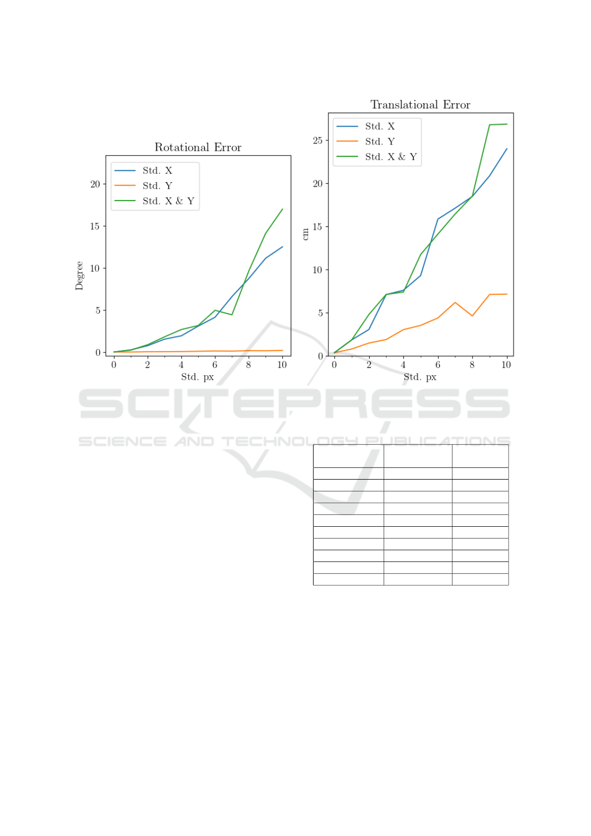
Figure 7: Impact of circle center detection error. The detected circle centers are varied by a normally distributed error with a
standard deviation denoted on the x-axis. y-axis denotes the rotational error (left) and translational error (right).
the dropout from 0% to 80% with an increment of
10%. In Table 1, we see that up until a dropout of
30% the calibration remains near 1 cm in translational
error and 0.5 degrees rotational error, which we deem
as acceptable calibration accuracy. With higher drop-
out, the error increases steadily, until at 70% the rota-
tional error spikes to 10 degrees, suggesting that the
reconstructed rays are inaccurate or missing. Inves-
tigation of the calibration data reveals that the algo-
rithm is only able to reconstruct a single ray. In order
to construct a ray, at least two 3D points are required,
but for the simulated drop-out of 70% and more, only
one potential ray had enough points associated with
it.
4.6 Impact of Distances
Our approach for estimating the relative orientation
and translation of a projector with respect to a stereo
camera relies on triangulating points from differ-
ent distances in order to perform ray intersection.
This experiment evaluates how much the range of
distances of the triangulated 3D points impacts the
calibration accuracy. We perform several calibrations
with different subsets of selected distances and com-
pare them with the baseline approach (2m, 5m, 8m,
Table 1: Calibration accuracy due to random drop-out, with
column Drop-Out indicating the drop-out percentage.
Drop-Out
Translational
Error
Rotational
Error
[cm] [deg]
Baseline (0 %) 0.36 0.35
10 % 0.99 0.44
20 % 1.22 0.47
30 % 1.60 0.50
40 % 2.18 0.53
50 % 2.20 0.68
60 % 3.62 0.79
70 % 5.52 10.00
80 % 18.01 10.00
12m, 17m, 23m, 26m). Table 2 shows that using cir-
cles from near distances leads to a better calibration
accuracy (IDs 1 - 4) than using only circles from far-
ther distances (IDs 5 - 9). We obtain the best results
by using the distances 2m and 5m (ID 2), namely a
translational error of 0.14 cm and a rotational error
of 0.42 degrees. We suspect this is caused by the 3D
triangulation becoming more sensitive to detection in-
accuracies the farther away the point is located, rela-
tive to the stereo cameras. The impact of 3D trian-
gulation error is discussed in greater detail in binocu-
Flexible Extrinsic Structured Light Calibration Using Circles
53
Table 2: Calibration accuracy across different distances rel-
ative to the structured light projector and the target calibra-
tion object. Row with ID 1 contains the baseline results.
ID Distances
Trans.
Error
Rot.
Error
[cm] [deg]
1 2m, 5m, 8m, 12m 0.36 0.35
17m, 23m, 26m
2 2m, 5m 0.14 0.42
3 2m, 26m 0.16 0.40
4 2m, 5m, 8m 0.23 0.39
5 23m, 26m 39.24 0.53
6 17m, 23m, 26m 7.31 0.37
7 8m, 12m 2.43 0.42
8 17m, 23m 9.13 0.40
9 12m, 17m 4.44 0.35
23m, 26m
lar stereo camera reconstruction literature (Guo et al.,
2006) (Xu et al., 2013). In Table 2, we see that the
proposed structured light extrinsic calibration method
estimates with satisfactory accuracy from 2m to 26m
(ID 1, 3) with a translational error of 0.36 cm and
0.35 degrees. Similar results are obtained from dis-
tances up to 8m, with up to 0.23 cm translational- and
0.42 degrees rotational error, respectively. In sum-
mary, we find that our approach is applicable for a
wide range of distances, especially when we compare
it to current state-of-the-art approaches (Chen et al.,
2018) (Huang et al., 2018).
4.7 Impact of Different Scenes
In this experiment, we analyze the impact of differ-
ent target scenes. Our method is intended to be used
in non-controlled environments. Hence, we perform
the calibration using our simulator described in Sec-
tion 4.2. We created multiple scenes: A scene con-
taining a white wall, a scene containing several geo-
metric shapes (cylinders with different surfaces) and a
scene consisting of a simulation of parked cars. Refer
to Figure 8 for images of the geometric shapes scene
and the car parking scene. The geometric shape scene
consists of multiple procedurally placed cylinders of
varying scale, position and rotation. We also vary the
surface of the cylinders using different albedo-color
and reflectivity values. The car parking scene consists
of five 3D-models of a car placed side-by-side. Us-
ing the synthetically rendered images, we perform an
extrinsic structured light calibration and summarize
our findings in Table 3. It shows that the rotational
error is relatively stable across different scenes, sug-
gesting that our method generalizes well for different
scenes. For all selected scenes, the translational error
Table 3: Calibration accuracy across different scenes.
Scene
Trans.
Error
Rot.
Error
[cm] [deg]
Baseline (White Wall) 0.36 0.35
Geometric Shapes 1.57 0.38
Parked Cars 1.57 0.37
and rotational error satisfy our accuracy constraints
of approximately 1 cm translational error and 1 de-
gree rotational error. Hence, our calibration method
yields satisfactory results for synthetically rendered
scenes, which may generalize to real-world applica-
tions as well.
5 CONCLUSION AND FUTURE
WORK
We have demonstrated the feasibility of a flexible
extrinsic structured light calibration approach. Our
calibration setup consists of two time-synchronized
cameras with known camera parameters (both intrin-
sics and extrinsics) and a projector capable of pro-
jecting a monochrome circle pattern into the scene.
Our method sequentially projects a known circle pat-
tern from different relative distances into the scene
and then triangulates the 3D positions of the detected
circles. After defining rays through the triangulated
3D points, the extrinsics of the projector are deter-
mined by calculating the intersection of these rays.
Our extensive evaluation shows that our approach
works with different projection surfaces and is rel-
atively stable towards different potentially negative
influences related to drop-out, circle detection, cali-
bration distances, etc.. Our implementation achieves
a rotational accuracy of below 1 degree and transla-
tional accuracy of approximately 1 cm. Our method
provides a calibration accuracy sufficient for intelli-
gent vehicle lighting systems (Tamburo et al., 2014)
or applications with requirements for similar preci-
sion, such as smart lighting installations (Sonam and
Harshit, 2019) and stage-productions (Gillette and
McNamara, 2020). Contrary to alternative solutions,
our method does not rely on finding a homography be-
tween the projected calibration pattern, thus allowing
the flexible extrinsic calibration of a structured light
projector on calibration surfaces that do not need to
be planar.
In the future, our approach could be generalized
to additionally estimate the intrinsics of a structured
light projector, as well as intrinsically and extrinsi-
cally calibrating the stereo-cameras themselves.
VISAPP 2023 - 18th International Conference on Computer Vision Theory and Applications
54
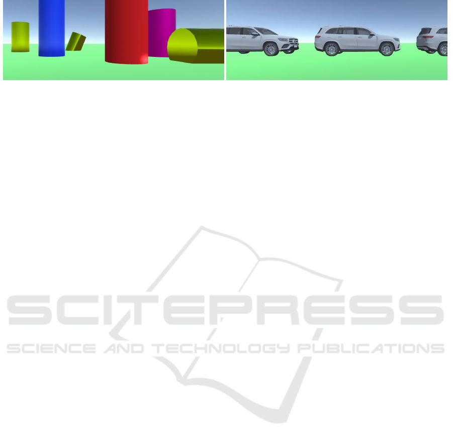
Figure 8: Simulated Geometric Shapes (left) and Parked Cars (right) test scenes.
ACKNOWLEDGEMENTS
This work was partly supported by the SmartPro-
tect project (no. 879642), which is funded through
the Austrian Research Promotion Agency (FFG) on
behalf of the Austrian Ministry of Climate Action
(BMK) via its Mobility of the Future funding pro-
gram.
The method described in this publication is
registered under the patent “Device and method
for calibrating a light projector” (AT523670A1 /
WO2021191121A1)
REFERENCES
Unity3D. https://unity.com/. Accessed: 2022-04-17.
An, Y., Bell, T., Li, B., Xu, J., and Zhang, S. (2016). Method
for large-range structured light system calibration. Ap-
plied optics, 55 33:9563–9572.
Chen, C., Gao, N., and Zhang, Z. (2018). Simple calibra-
tion method for dual-camera structured light system.
Journal of the European Optical Society-Rapid Publi-
cations, 14:1–11.
Chen, R., Xu, J., Chen, H., Su, J., Zhang, Z., and Chen,
K. (2016). Accurate calibration method for camera
and projector in fringe patterns measurement system.
Applied Optics, 55(16):4293–4300.
Garrido-Jurado, S., Mu
˜
noz-Salinas, R., Madrid-Cuevas, F.,
and Mar
´
ın-Jim
´
enez, M. (2016). Simultaneous re-
construction and calibration for multi-view structured
light scanning. Journal of Visual Communication and
Image Representation, 39.
Gillette, J. M. and McNamara, M. J. (2020). Designing With
Light - An Introduction to Stage Lighting. Routledge.
Guo, Y., Yao, Y., and Di, X. (2006). Research on structural
parameter optimization of binocular vision measuring
system for parallel mechanism. In Proc. IEEE In-
ternational Conference on Mechatronics and Automa-
tion, pages 1131–1135.
Huang, B., Ozdemir, S., Tang, Y., Liao, C., and Ling, H.
(2018). A single-shot-per-pose camera-projector cal-
ibration system for imperfect planar targets. In IEEE
International Symposium on Mixed and Augmented
Reality Adjunct, pages 15–20.
Huynh, D. (2009). Metrics for 3d rotations: Comparison
and analysis. Journal of Mathematical Imaging and
Vision, 35:155–164.
Liu, J., Zhang, Y., and Li, Z. (2006). Selection of cameras
setup geometry parameters in binocular stereovision.
In Proc. IEEE Conference on Robotics, Automation
and Mechatronics, pages 1–6.
Megiddo, N. and Tamir, A. (1983). Finding least-distances
lines. Siam Journal on Algebraic and Discrete Meth-
ods, 4.
Packer, O., Diller, L. C., Verweij, J., Lee, B. B., Poko-
rny, J., Williams, D. R., Dacey, D. M., and Brainard,
D. H. (2001). Characterization and use of a digital
light projector for vision research. Vision Research,
41(4):427–439.
Pharr, M., Wenzel, J., and Humphreys, G. (2016). Physi-
cally Based Rendering: From Theory to Implementa-
tion. Morgan Kaufmann Publishers Inc., 3rd edition.
Redmon, J., Divvala, S., Girshick, R., and Farhadi, A.
(2016). You only look once: Unified, real-time ob-
ject detection. In Proc. IEEE conference on computer
vision and pattern recognition, pages 779–788.
Shahpaski, M., Sapaico, L. R., Chevassus, G., and
S
¨
usstrunk, S. (2017). Simultaneous geometric and ra-
diometric calibration of a projector-camera pair. In
Proc. IEEE Conference on Computer Vision and Pat-
tern Recognition, pages 3596–3604.
Smith, A. R. (1983). The viewing transformation. Com-
puter Graphics Project, Computer Division, Lucas-
film, Ltd. Technical Memo, (84).
Sonam, T. and Harshit, S. M. (2019). Smart lightning and
security system. In Proc. IEEE International Confer-
ence on Internet of Things: Smart Innovation and Us-
ages, pages 1–6.
Tamburo, R. J., Nurvitadhi, E., Chugh, A., Chen, M., Rowe,
A. G., Kanade, T., and Narasimhan, S. G. (2014). Pro-
grammable automotive headlights. In Proc. European
Conference on Computer Vision, pages 750–765.
Xu, Y., Zhao, Y., Wu, F., and Yang, K. (2013). Er-
ror analysis of calibration parameters estimation for
binocular stereo vision system. In Proc. IEEE Inter-
national Conference on Imaging Systems and Tech-
niques, pages 317–320.
Zhang, D. and Yau, S.-T. (2008). Absolute phase-assisted
three-dimensional data registration for a dual-camera
structured light system. Applied Optics, 47 17:3134–
42.
Zhang, Z. (2000). A flexible new technique for camera cal-
ibration. IEEE Transactions on Pattern Analysis and
Machine Intelligence, 22:1330–1334.
Flexible Extrinsic Structured Light Calibration Using Circles
55
