
Improved Directional Guidance with Transparent AR Displays
Felix P. Strobel
1 a
and Voicu Popescu
2 b
1
Department of Informatics, Karlsruhe Institute of Technology, Karlsruhe, Germany
2
Department of Computer Science, Purdue University, 305N University Street, West-Lafayette, U.S.A.
Keywords:
Simulated Transparent Display, Robust Implementation, Augmented Reality.
Abstract:
In a popular form of augmented reality (AR), the scene is captured with the back-facing camera of a hand-
held phone or tablet, and annotations are overlaid onto the live video stream. However, the annotations are
not integrated into the user’s field of view, and the user is left with the challenging task of translating the
annotations from the display to the real world. This challenge can be alleviated by modifying the video frame
to approximate what the user would see in the absence of the display, making the display seem transparent.
This paper demonstrates a robust transparent display implementation using only the back-facing camera of a
tablet, which was tested extensively over a variety of complex real world scenes. A user study shows that the
transparent AR display lets users locate annotations in the real world significantly more accurately than when
using a conventional AR display.
1 INTRODUCTION
Augmented Reality (AR) is a powerful human-
computer interface that allows overlaying computer-
generated graphical annotations directly onto the
user’s view of the real world. The goal is to anchor
the annotations to the real world elements that they
describe, saving the user the cognitive effort of trans-
lating the annotations from a conventional computer
display to the real world.
A popular implementation of AR interfaces relies
on handheld AR displays: the user views the scene on
a phone or computer tablet that shows a live video
of the scene augmented with graphical annotations
(Mohr et al., 2017; Grubert et al., 2014). Such AR
displays have the advantages of being already mass
deployed, of being familiar to most users, and of so-
cial acceptance. The disadvantages of AR displays
include lack of depth cues, reduced field of view, and
lack of true transparency.
Indeed, phones and tablets only simulate trans-
parency by displaying the frame captured by the back-
facing camera. Since the frame is captured from the
camera’s and not the user’s viewpoint, and since the
camera’s field of view is different from the angle sub-
tended by the display in the user’s visual field, the
frame is only a poor approximation of what the user
a
https://orcid.org/0000-0002-2740-5169
b
https://orcid.org/0000-0002-8767-8724
would see if the display were made of transparent
glass. This results in redundancy and discontinuity
between what the user sees on and what the user sees
around the display (Pucihar et al., 2013). This dual-
view problem makes conventional AR displays im-
perfect AR interfaces, as the annotations are not di-
rectly integrated into the user’s view of the real world,
but rather into the view of the back-facing camera.
Therefore, AR displays do not completely relieve the
user from the cognitive effort of translating the anno-
tations from the computer display to their own view of
the real world. A truly transparent display shows ex-
actly what the user would see if the display were not
there. Manufacturing transparent phones and tablets
presents difficult technological challenges, as many
components are opaque and large.
In order to modify the back-facing camera frame
to match what the user would see in the absence of
the AR display, two pieces of information are needed:
the position of the user’s head, and the geometry of
the scene. Leveraging this information, the frame
can be re-projected to the user’s viewpoint using con-
ventional projective texture mapping (Andersen et al.,
2016). Prior work on simulating AR display trans-
parency through user-perspective rendering has ex-
amined various modalities for tracking the user head
and acquiring scene geometry, as well as approxi-
mations that bypass the need for this information.
Some high-end tablets and phones can now track the
Strobel, F. and Popescu, V.
Improved Directional Guidance with Transparent AR Displays.
DOI: 10.5220/0011613200003417
In Proceedings of the 18th International Joint Conference on Computer Vision, Imaging and Computer Graphics Theory and Applications (VISIGRAPP 2023) - Volume 1: GRAPP, pages
27-38
ISBN: 978-989-758-634-7; ISSN: 2184-4321
Copyright
c
2023 by SCITEPRESS – Science and Technology Publications, Lda. Under CC license (CC BY-NC-ND 4.0)
27
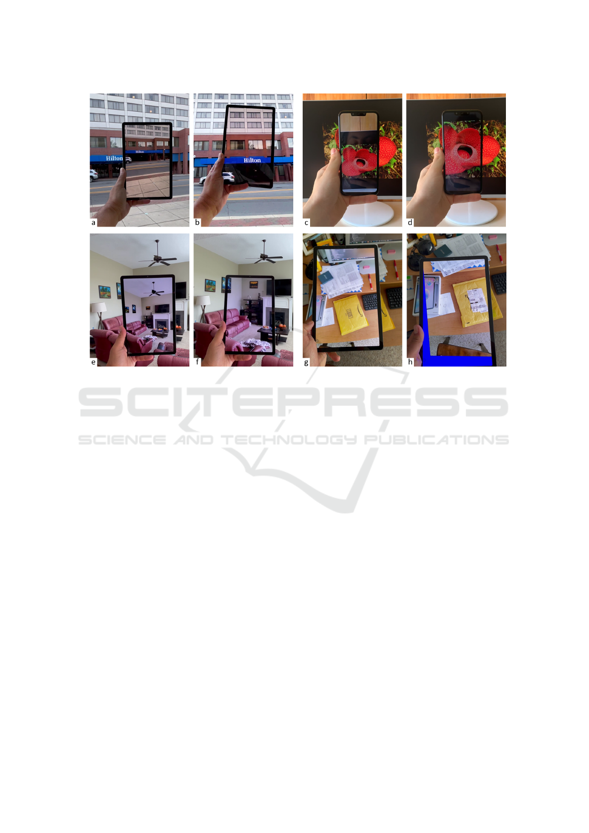
Figure 1: Conventional (left of each pair) and our transparent (right) AR display.
user’s head using the front-facing camera, and can ac-
quire scene geometry actively using on-board depth
cameras, or passively through structure-from-motion.
However, no robust transparent AR display has yet
been demonstrated and tested with users, and the AR
displays used in practice continue to suffer from the
dual-view problem.
In this paper we build upon prior work on user-
perspective rendering to demonstrate a simulated
transparent display that works robustly for a variety
of complex scenes, that is implemented with a sim-
ple phone or tablet with just a back-facing camera,
and that improves the directional guidance provided
to the user. The design of our transparent display is
anchored by two considerations.
First, we argue that for some AR applications the
computational or hardware expense of tracking the
user’s head is unnecessary; indeed, as the user exam-
ines various parts of the scene, they are likely to move
their head and arm together, holding the phone or
tablet in a little-changing ergonomic sweet spot, much
the same as when photographing or video record-
ing a scene; the user naturally holds the phone to
see it straight on, avoiding skewed viewing angles.
Since the user can comfortably hold the display in
a stable sweet spot, it is reasonable to expect their
cooperation, and not be concerned about adversarial
behavior–the point is not that a user could easily break
the illusion of transparency by looking at their phone
at a shallow angle, but rather that the user could easily
hold it such that transparency works to provide accu-
rate directional guidance. Furthermore, in some AR
applications such as driver assistance, the user’s head
is naturally at a constant position relative to the dis-
play.
Second, we argue that robust, complete, and real
time scene geometry acquisition will not be tractable
in the near future, and therefore suitable scene geom-
etry approximations have to be found to allow hand-
held AR reach its potential for wide adoption. Ac-
quiring quality depth of a dynamic scene with intri-
cate geometry, such as a water fountain or a leafy tree
swaying in the wind remains a challenging technolog-
ical problem; furthermore, even if future generation
phones or tablets acquire perfect depth for such chal-
lenging scenes, the depth acquired from the device
perspective might not be enough, as the user could
see parts of the scene that are occluded from the de-
vice perspective.
Based on these considerations, we have devised
our AR display (1) to cater to a fixed user viewpoint,
and (2) to map the frame to the user view through
a homography defined either by a planar proxy of
the scene geometry, or by the distant geometry as-
sumption. Our AR display is robust, avoiding the ob-
jectionable artifacts caused by user head tracking or
GRAPP 2023 - 18th International Conference on Computer Graphics Theory and Applications
28

scene geometry acquisition errors.
Fig. 1 illustrates the improved transparency
achieved by our AR display, compared to a conven-
tional AR display. The transparent AR display was
implemented with the distant geometry assumption
for examples (b) and (f) and with the planar proxy
assumption for (d) and (h). The distant geometry as-
sumption works well even for the living room scene
(f) where scene geometry is between one and five me-
ters away from the user. In (h), the desk is close to
the large tablet and some parts of the scene (blue) oc-
cluded by the tablet and hence needed for the trans-
parency effect were not captured by the tablet’s back-
facing camera; in (d) the camera of the (smaller)
phone captures all needed pixels. Our AR display
achieves good transparency, which improves direc-
tional guidance. Consider an AR application that in-
dicates a specific window by circling it on the fac¸ade
shown in (a) and (b); the transparent display (b) will
place the circle correctly on the line connecting the
user viewpoint to the actual location of the window in
the real world, providing the user with the true direc-
tion to the window of interest; on the other hand, the
conventional display (a) does not directly point to the
location of the window in the real world; the user has
to study the visualization closely to memorize the lo-
cation of the window relative to unique visual features
and then to translate the memorized location from the
visualization to the real world.
We have compared our transparent AR displays to
conventional AR displays both analytically and em-
pirically, for a variety of complex scenes, and the
results show that our displays have superior trans-
parency accuracy. We have also conducted a con-
trolled user study (N = 17), which showed that, com-
pared to a conventional AR display, our transparent
AR display reduced annotation localization error by a
statistically significant 61%. Our transparent AR dis-
play is robust, ready to be enrolled in AR applications.
We also refer the reader to the accompanying video.
In summary, our paper makes the following con-
tributions:
• The design of a practical transparent AR display,
validated analytically and empirically.
• The implementation of a robust transparent AR
display prototype that produces a quality trans-
parency approximation regardless of scene com-
plexity, motion, and lighting conditions.
• A controlled user study that confirms the supe-
rior directional guidance afforded by the proposed
transparent AR display.
2 PRIOR WORK
The holy grail of AR interfaces is an HMD in the
form factor of regular vision glasses or even con-
tact lenses. Whereas considerable progress has been
made, optical see-through AR HMDs remain bulky,
expensive, with a limited field view, dim, and with-
out the ability to render with full opacity. Therefore,
researchers have been exploring an alternative AR in-
terface, where the user holds a simulated transparent
display that overlays graphical annotations onto the
scene.
An early implementation uses a head-mounted
projector and a handheld screen, which, despite the
user encumbrance, demonstrates the feasibility and
benefit of a handheld simulated transparent display
(Yoshida et al., 2008). Subsequent AR transparent
displays leverage portable active displays with built-
in cameras. One challenge is to register the dis-
play in the user’s frame, which was addressed with
a camera mounted on the user’s head (Samini and
Palmerius, 2014; Bari
ˇ
cevi
´
c et al., 2012), or with a
camera mounted on the handheld display and aimed
at the user (Bari
ˇ
cevi
´
c et al., 2017; Grubert et al., 2014;
Hill et al., 2011; Matsuda et al., 2013; Tomioka et al.,
2013; Uchida and Komuro, 2013; Zhang et al., 2013;
Andersen et al., 2016).
A second challenge is to acquire the scene geom-
etry and color in real time. Several simulated trans-
parent display prototypes work under the assumption
that the scene is planar. The planar scene proxy is ei-
ther precalibrated (Matsuda et al., 2013; Zhang et al.,
2013), or tracked using markers added to the scene
(Grubert et al., 2014; Hill et al., 2011; Samini and
Palmerius, 2014; Uchida and Komuro, 2013) or us-
ing scene features (Tomioka et al., 2013). Other re-
searchers have opted for per-pixel depth acquisition,
with on-board depth cameras (Bari
ˇ
cevi
´
c et al., 2012;
Andersen et al., 2016), or through structure from mo-
tion (Bari
ˇ
cevi
´
c et al., 2017). The planar scene proxy
approach has the advantage of greatly simplifying
depth acquisition, and of hiding disocclusion errors.
The per-pixel depth approach has the potential for
more accurate transparency as the scene geometry is
captured with greater fidelity, but is is hampered by
artifacts due to depth acquisition imperfections, and
to disocclusion errors due to parts of the scene visi-
ble from the user viewpoint but not from the camera
viewpoint.
Another goal in transparent AR display devel-
opment was untethering the device to achieve com-
plete portability. Whereas early prototypes required
wire connections to power sources, trackers, or
workstations, the advances of smartphone and com-
Improved Directional Guidance with Transparent AR Displays
29

puter tablet technology has enabled compact, self-
contained handheld AR displays (Grubert et al., 2014;
Matsuda et al., 2013; Samini and Palmerius, 2014;
Zhang et al., 2013; Bari
ˇ
cevi
´
c et al., 2017; Bari
ˇ
cevi
´
c
et al., 2012; Andersen et al., 2016).
The dual-view problem was noted early on in
studies that showed that users expect the display
to simulate transparency accurately (Pucihar et al.,
2013). Early prototypes assumed a fixed user view-
point (Pucihar et al., 2013), and subsequent proto-
types investigated tracking the user head. One sys-
tem (Mohr et al., 2017) tracks the user head with a
front-facing camera. To make the computational cost
tractable, the user head is not tracked every frame.
Even so, the computational demand exceeded what
the phone could sustain and the user study was con-
ducted on a PC workstation. The study revealed that
users perform better in a fixed-viewpoint condition
compared to the full head tracking condition, and the
difference was attributed to head-tracking failures.
Researchers have analyzed the potential of planar
approximations of scene geometry (Borsoi and Costa,
2018), but they did not consider the distant geometry
(”plane at infinity”) approximation; furthermore, the
proposed approximations were not implemented on a
portable AR display, and they were not tested with
users. We show that the distant geometry based ho-
mography yields good results even for scenes a few
meters away from the user, bypassing scene geome-
try acquisition altogether. Furthermore, we have im-
plemented our design in a robust prototype which we
have user tested successfully.
Our work is inspired by that of Andersen et al.
(Andersen et al., 2016), who examined the feasibility
of transparent AR display implementation by taking
advantage of emerging features of phones and tablets.
They describe three transparent AR display proto-
types. One prototype leverages hardware user track-
ing provided by a phone with four front-facing cam-
eras, one at each display corner. A second prototype
leverages the on-board depth camera of a computer
tablet to capture the scene geometry. A third proto-
type combines the other two prototypes to achieve
both user tracking and scene geometry acquisition.
The two prototypes that rely on depth acquisition suf-
fer from objectionable artifacts due to depth and dis-
occlusion errors. The prototypes are not tested with
users. Our work provides analytical and empirical
evidence that transparent AR displays can be imple-
mented with any phone or tablet, without the prereq-
uisites of advanced features such as user tracking or
depth acquisition, and we demonstrate the improved
directional guidance achieved by our transparent AR
display in a user study.
3 SIMULATING AR DISPLAY
TRANSPARENCY
Since truly transparent tablets and phones are not
yet feasible, one is left with simulating transparency
in video-see-through fashion, leveraging the back-
facing camera that captures the scene in real time.
One option is to simply display the camera frames
as is. This is the option currently taken by most if
not all AR applications, and we refer to this option
as the conventional AR display. Since the user view-
point is different from that of the camera, the trans-
parency effect can be improved by reprojecting the
camera frame to the user viewpoint. Reprojecting the
frame to the user viewpoint requires (1) knowledge of
the 3D scene geometry, as the reprojection includes a
translation from the camera to the user viewpoint, and
requires (2) knowledge of the user viewpoint, as what
the user sees through an ideal glass-like transparent
AR display depends on where the user’s head is with
respect to the display.
(1) Recent high-end phones have some depth ac-
quisition capability. However, real time depth ac-
quisition of scenes with intricate or dynamic geom-
etry, such as a leafy plant swaying in the breeze, or
of scenes with complex reflective properties, such
as a water fountain, remains challenging. Further-
more, even if the back-facing camera acquires perfect
per-pixel depth, the resulting simulated transparency
might still suffer from severe artifacts due to occlu-
sions. In Fig. 2a, reprojecting to U the color and depth
acquired from C results in artifacts due to the missing
samples of the left face of the box. In other words,
accurate transparency requires quality and robust real-
time depth acquisition from not one, but from multi-
ple viewpoints. We submit that depth acquisition can
be bypassed altogether by mapping the camera image
to the user image with a homography, which results
in a quality simulated transparency approximation, as
we show analytically and empirically in the following
sections.
(2) Recent high-end tablets and phones also pro-
vide user-head tracking, leveraging on-board sensors
that are aimed at the user (front-facing). These ad-
ditions are motivated by the popularity of AR en-
hancements of video conferencing applications, such
as modifying the appearance of the speaker by chang-
ing their facial features or by attaching graphics to the
speaker’s head. Such applications require tracking the
user’s head with six degrees of freedom. However, for
our application of transparent AR displays, only the
three translations that place the user’s head with re-
spect to the display are needed, because the rotations
do not change what the user sees through the display
GRAPP 2023 - 18th International Conference on Computer Graphics Theory and Applications
30
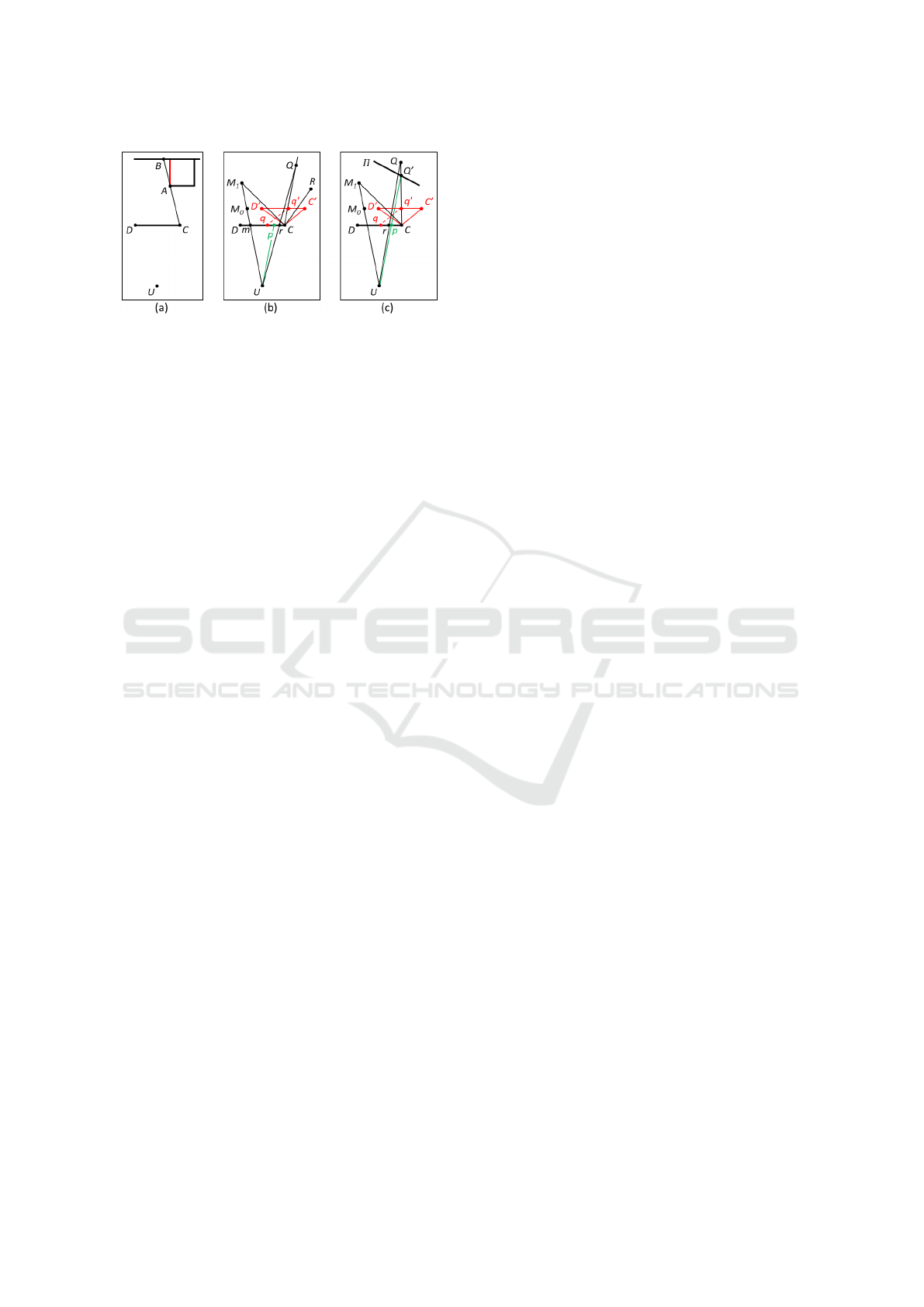
Figure 2: (a) Disocclusion artifacts. The left side of the box
(red) is missed by the back-facing camera C located at the
corner of the AR display DC, but is visible from the user
viewpoint U. Even with perfect depth, reprojecting to U a
color and depth frame acquired from C results in disocclu-
sion artifacts. (b) AR display transparency with the distant
geometry assumption. A pixel p is looked up in camera
frame D
′
C
′
along a ray from C with direction U p, setting
it to the color at q
′
. (c) AR display transparency with the
planar proxy geometry approximation. A pixel p is looked
up in camera frame D
′
C
′
by projecting its proxy point Q
′
to
q
′
.
frame. Furthermore, in video conferencing applica-
tions the user frequently moves their head with re-
spect to the tablet or phone. This is especially true
in the common use case when the device is placed
in a bracket that anchors it to the scene (e.g., table-
top, car dashboard), and not to the user. However,
in transparent display AR applications the user typi-
cally holds the display at a fixed position with respect
to their head, moving the display as they pan and tilt
their view direction, much the same way they hold
the display when it serves as a viewfinder when tak-
ing photos. We submit that user head tracking can be
bypassed altogether by assuming that the user’s head
is in a default position, which results in a quality sim-
ulated transparency approximation, as we show ana-
lytically and empirically in the following sections.
3.1 Geometric Accuracy of AR Display
Transparency
We first define three measures of AR display trans-
parency error which we then use to quantify the qual-
ity of our AR transparent display approximations.
Please also refer to Fig. 3.
Reprojection Error ε. Given a 2D point p on an
approximate transparent display that shows 3D scene
point P, the reprojection error ε at p is defined with
Fig. 2, where q is the projection of P on a perfectly
accurate transparent display. In other words, pixel p
is ε away from its true position.
ε = ∥p − q∥ (1)
The reprojection error ε is measured in pixels and
it can be converted to units of length, e.g., mm, by tak-
ing into account the physical size of the display. The
reprojection error can also be measured in degrees, as
the size of the angle between the user rays through p
and q, which indicates how far off the direction in-
dicated by the AR display is from the true direction
in the real world scene. We quantify the reprojection
error over the entire transparent display as the aver-
age and maximum reprojection errors over all pixel
centers.
Number of Missing Pixels µ. Another measure of
the difference between the image I
∗
shown by an ap-
proximate transparent display and the image I shown
by a perfectly accurate transparent display is the num-
ber µ of pixels in I that are missing from I
∗
. We ex-
press µ as a percentage from the total number of pix-
els in I, to make it resolution independent. There are
three types of missing pixels: (1) pixels not captured
by the camera because they correspond to 3D scene
points outside the camera’s view frustum, like the
blue pixels in Fig. 1h; (2) pixels not captured by the
camera because they correspond to 3D scene points
that are inside the camera’s view frustum but are not
visible to the camera due to occlusions (Fig. 2a); and
(3) pixels captured by the camera but incorrectly dis-
carded by the transparency approximation.
Number of Redundant Pixels ρ. Another measure
of the difference between the image I
∗
shown by
an approximate transparent display and the image I
shown by a perfectly accurate transparent display is
the number ρ of pixels in I
∗
that are missing from
I, i.e., pixels that should not be part of I
∗
. These
pixels correspond to parts of the scene that the user
sees directly, around the display, and they are shown
redundantly on the approximate transparent display,
creating a double vision artifact. We express ρ as a
percentage from the total number of pixels in I
∗
, to
make it resolution independent. In Fig. 1e, the pixels
of the ceiling fan are redundant as the fan is directly
visible to the user above the display.
3.2 Homography-based AR Display
Transparency
Connecting the camera and user views using a ho-
mography allows modifying the frame acquired by
the camera to better approximate what the user would
see through a perfectly transparent display, while by-
passing depth acquisition, and while avoiding arti-
facts due to occlusions. Using Fig. 2a again, repro-
Improved Directional Guidance with Transparent AR Displays
31

jecting the frame with a homography, which is a bi-
jective mapping, keeps the projection of points A and
B at the same display location, preventing the disoc-
clusion error gap from forming. We have investigated
two options for defining the homography between the
user and camera views.
3.2.1 Distant Geometry Assumption
The first option is to assume the scene geometry is
far away from the display, which allows ignoring the
distance between the camera viewpoint and the user
viewpoint. In Fig. 2b, the AR display DC has a
back-facing video camera at C, with frustum D
′
CC
′
.
Transparency is approximated by mapping each dis-
play pixel p to the camera frame based solely on the
direction of the pixel’s ray U p.
A transparent display pixel (u,v) is mapped to the
camera frame as follows. First, the 3D point p cor-
responding to pixel center is computed with Fig. 2,
where the user view frustum (i.e., DUC in Fig. 2) is
encoded as a planar pinhole camera with the eye at
the user viewpoint U, with row and column vectors
a
u
and b
u
, and with eye to top left image corner vec-
tor c
u
. We use column vectors.
p = U +
a
u
b
u
c
u
u v 1
T
(2)
Then ray U p is translated to C and its tip is pro-
jected with the camera to obtain the frame mapping
(u
q
,v
q
), using Fig. 3.
C + p −U = C +
a
c
b
c
c
c
u
q
w
q
v
q
w
q
w
q
T
(3)
The 3D vector Fig. 3 has three scalar equations,
i.e., one for each of the three dimensions x, y, and z,
and three unknowns, i.e., u
q
, v
q
, and w
q
, which are
found by solving as shown in Fig. 4.
u
q
w
q
v
q
w
q
w
q
T
=
a
c
b
c
c
c
−1
(p−U) (4)
The reprojection error ε
d
introduced by the distant
geometry assumption is computed as follows. Given
pixel p, the transparent display sets it to the color
of the camera frame at q
′
, where the camera cap-
tured the 3D scene point Q. The true projection of
Q on the transparent display is at r, so ε
d
= ∥p − r ∥.
The conventional AR display, which shows the cam-
era frame as is, projects Q at q, which has the same
image coordinates as q
′
, for a reprojection error of
ε
c
= ∥q − r∥. As can be seen in Fig. 2b, even for
a 3D scene point Q that is fairly close to the dis-
play, the transparency achieved with the distant geom-
etry assumption improves over the conventional trans-
parency, i.e., ε
d
< ε
c
. As expected, the transparency
error decreases as the distance to the scene increases.
As Q moves farther from C on Cq
′
, r moves closer to
p, reducing ε
d
, while ε
c
stays the same. At the limit,
the distant geometry assumption yields a perfectly ac-
curate transparent display (Fig. 5).
lim
Q→∞
ε
d
= 0, lim
Q→∞
ε
c
= ∥p − q∥ (5)
Our transparent display has missing pixels. One
example is the pixel corresponding to M
0
in Fig. 2b,
which was not captured by the camera, and is there-
fore missing from the conventional AR display as
well. Another example is the pixel corresponding to
M
1
, which is captured by the camera but it is dis-
carded since the direction CM
1
is beyond the left
boundary DU of the user view frustum.
Even for large tablets (e.g., 50cm), the angle sub-
tended by the display in the user’s field of view (e.g.,
53
◦
at 50cm) is smaller than the field of view of the
camera. Therefore, the reprojection implemented us-
ing the distant geometry assumption is essentially a
zoom in operation. As such, our transparent display
does not have redundant pixels. Consider a 3D scene
point that the user sees directly, beyond the display,
e.g., R in Fig. 2b. A ray from U with direction CR is
to the right of CU , so R does not appear on the trans-
parent display. The conventional AR display does
have redundant pixels: R is captured by the camera
and hence shown on the display, in addition to being
seen directly by the user.
3.2.2 Analysis of Distant Geometry Assumption
We have analyzed our transparent display based on
the distant geometry assumption and we have com-
pared it to a conventional AR display using a soft-
ware simulator (Fig. 3). The simulator models a 23cm
× 14cm tablet (10.5inch diagonal) with an 80
o
back-
facing camera at its top right corner. These param-
eters correspond to the wide angle back camera of
a Samsung Tab6 (Fig. 1) The user views the tablet
perpendicularly to its center from a distance of 50cm.
The 3D scene is a vertical wall texture mapped with
the photograph of a painting. The wall is pushed back
to various distances, while scaling up the painting to
keep the user’s view of the real world unchanged. The
scaling has no effect on the performance of either dis-
play, it is done for illustration eloquence. The dis-
tant geometry assumption works well even when the
scene is 2m away from the display, where it improves
the transparency effect over the conventional display
by removing the redundant pixels and by reducing the
reprojection error. The largest errors are at the left and
bottom edges of our transparent display, which are
farthest from the top-right camera. At 5m, the visu-
GRAPP 2023 - 18th International Conference on Computer Graphics Theory and Applications
32
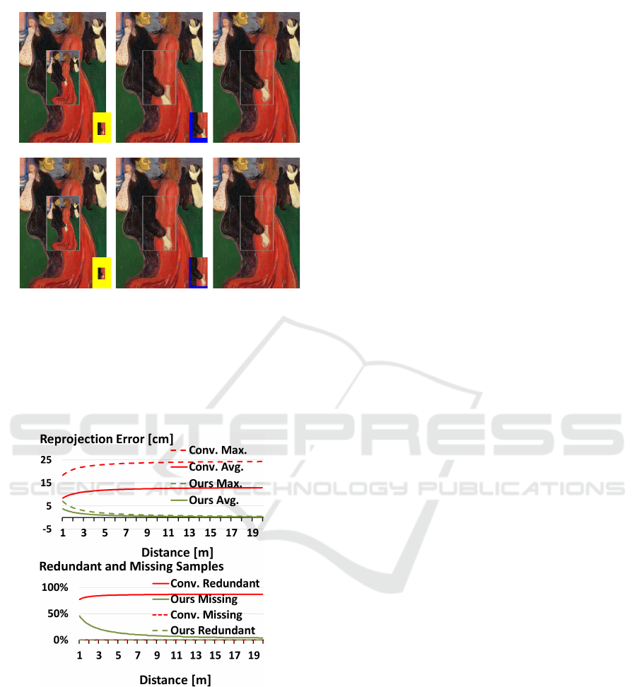
d = 2m
ε = 10cm, ρ = 82%
ε = 2.4cm, μ = 30%
Conventional Ours Ground truth
d = 5m
ε = 12cm, ρ = 86% ε = 1.0cm, μ = 14%
Figure 3: Software simulator comparison between three AR
displays: a conventional one that shows the camera frame
as is, ours based on the distant geometry assumption, and
ground truth with perfect transparency. The bottom right
vignettes show the redundant (yellow) and missing (blue)
pixels. Our display improves over the transparency of the
conventional display even at 2m, and, at 5m, our display
transparency is close to ground truth.
Figure 4: (Top) Average and maximum reprojection errors
for the conventional and the distant geometry transparent
AR displays, as a function of scene distance. (Bottom)
Missing and redundant pixels for the conventional and the
distant geometry transparent displays, as a function of scene
distance.
alization discontinuity across the frame of the display
is barely noticeable. The reprojection error and the
redundancy of the conventional AR display are large,
and they increase with distance.
Fig. 4, left, shows that our transparent display
has smaller maximum and average reprojection errors
compared to the conventional AR display for any dis-
play to scene distance beyond 1m. At 2m, 3m, 5m,
10m, and 20m, the average reprojection error for our
display is 2.4cm, 1.7cm, 1.0cm, 0.54cm, and 0.27cm.
Using the 50cm user viewpoint distance, these trans-
late to directional errors of 2.7
◦
, 1.9
◦
, 1.1
◦
, 0.6
◦
, and
0.3
◦
. The conventional display has large and growing
average reprojection errors of over 10cm (11
◦
). Fig. 4,
right, shows that no matter the distance to the scene,
our transparent display has no redundant pixels, and
that the percentage of missing pixels decreases with
distance. The conventional AR display has no miss-
ing pixels, but over 80% of its pixels show the user
a part of the real world that they already see directly,
around the display.
3.2.3 Planar Proxy Geometry Approximation
The second option we have investigated is to build
the homography by approximating the scene geome-
try with a plane. In Fig. 2c the scene planar proxy is
Π. Transparency is approximated by mapping each
display pixel (u,v) to the camera frame by computing
the pixel center 3D point p using Fig. 2, by comput-
ing the intersection Q
′
of ray U p with Π by solving
the system Fig. 6 where n and p
0
are the normal and
a point of Π, and by projecting Q
′
with the camera to
frame point (u
q
,v
q
) using Fig. 7.
n(p
0
− Q
′
) = 0
Q
′
= U + (p −U)w
q
(6)
u
q
w
q
v
q
w
q
w
q
T
=
a
c
b
c
c
c
−1
(Q
′
−C)
(7)
Since the proxy is only an approximation of the
scene geometry, the 3D scene point captured by the
camera at q
′
is Q and not Q
′
, which translates to a
reprojection error ε
p
= ∥p − r∥, where r is the pro-
jection of Q onto DC as seen from U. The closer
a 3D scene point is to the proxy, the smaller its re-
projection error; points on the proxy have a repro-
jection error of 0. The farther the geometry, the less
impact a given out-of-proxy displacement has, due to
perspective foreshortening. Like before, conventional
AR display projects Q to q for a reprojection error
ε
c
= ∥q −r∥.
Like the distant geometry display, the planar
proxy display can have missing pixels, e.g., M
0
in
Fig. 2c, which was not captured by the camera, and
M
1
, whose proxy point is outside the user view frus-
tum as Π intersects CM
1
to the left of UD. Unlike
the distant geometry display, the planar proxy display
can have redundant pixels. In Fig. 5a, the 3D scene
Improved Directional Guidance with Transparent AR Displays
33
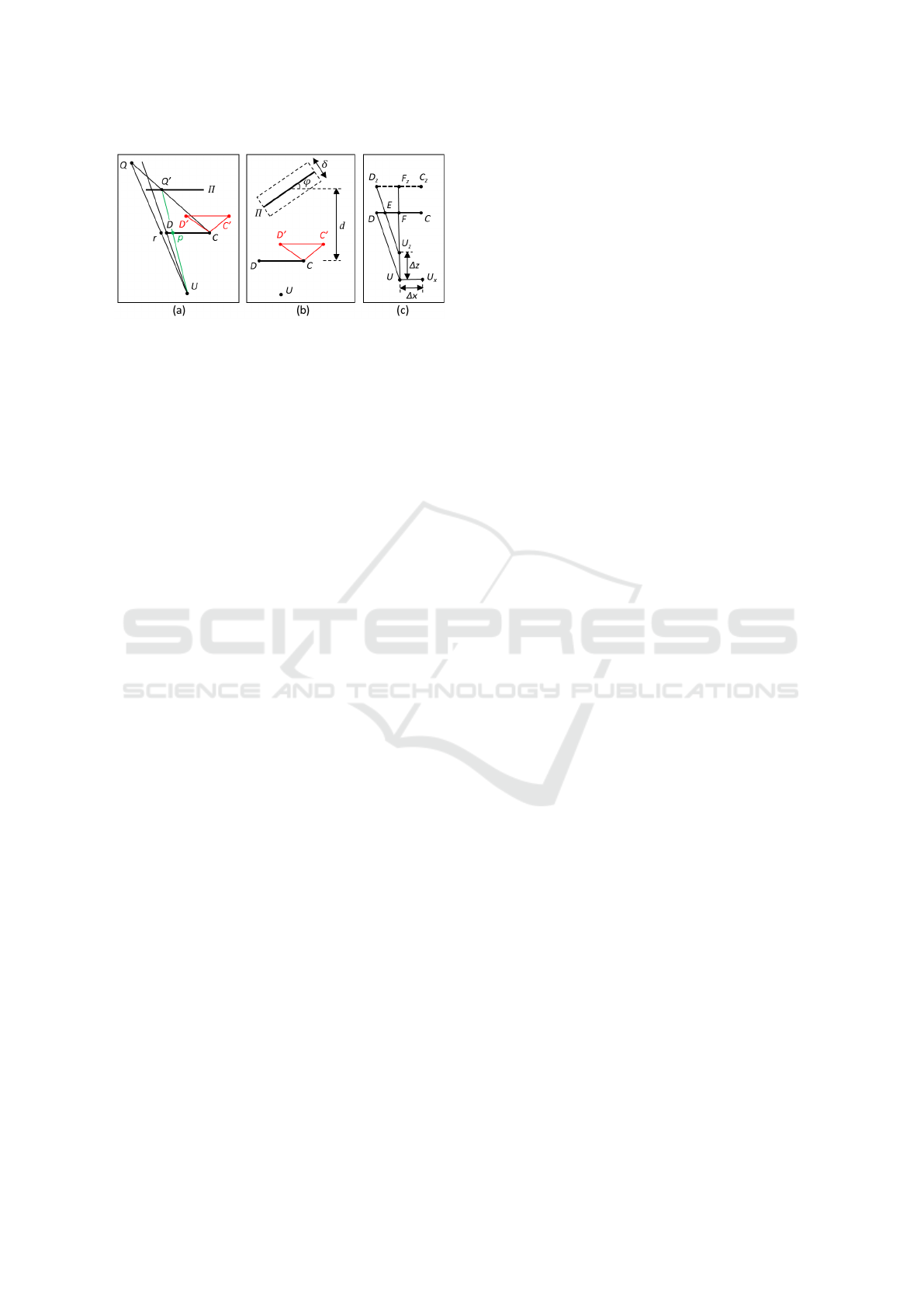
Figure 5: (a) Redundancy example for planar proxy trans-
parent display: point Q is seen directly by the user as ray
UQ is not blocked by the display DC, and it also appears
on the transparent display at p. (b) Simulator setup for the
analysis of the planar proxy geometry approximation. (c)
User viewpoint deviation from assumed position U.
point Q is seen by the user directly as its projection r
is outside the display DC. However, the correspond-
ing proxy point Q
′
projects inside the display at p, so
the user also sees Q on the display, redundantly.
3.2.4 Analysis of Planar Geometry Assumption
We have analyzed the quality of the transparent dis-
play obtained with the planar geometry assumption
using a simulator configured as shown in Fig. 5b. The
proxy plane Π is at distance d = 1m from the dis-
play DC, it is vertical, and it makes an angle φ = 45
◦
with the display plane. The actual 3D scene has a dis-
placement out of the proxy plane between +δ/2 and
−δ/2, with δ = 50cm. In summary, when the scene is
farther than the proxy, i.e., δ = -25cm, our display has
a few redundant pixels, and no missing pixels; when
the scene is closer than the proxy, i.e., δ = 25cm, our
display has no redundant pixels, and a few missing
pixels. In all cases, our display provides acceptable
transparency, i.e., there is good visualization continu-
ity across the display frame. The conventional dis-
play suffers from substantial redundancy and provides
a poor transparency effect. The planar proxy display
has a small reprojection error, which decreases as the
quality of the geometry approximation provided by
the proxy increases. The planar proxy display has a
smaller reprojection error than the conventional dis-
play.
3.3 Default Head Position AR Display
Transparency
We propose to implement transparent displays by by-
passing user head tracking, under the assumption that
the user viewpoint is in a default position. Since in
practice the user viewpoint will deviate from the de-
fault position, we now analyze the implications of
such deviations on the reprojection error.
Given an actual user viewpoint U
∗
that is assumed
to be at U, the component of the U
∗
U translation vec-
tor parallel to the display is added directly to the re-
projection error, shifting up by ∆x the graphs given in
Fig. 4. In Fig. 5c the actual user viewpoint U
x
is to
the right of the assumed viewpoint U and the trans-
parent display reprojection error ε increases by ∆x.
The reprojection error is typically less sensitive to the
translation vector component perpendicular to the dis-
play. In Fig. 5c, when the actual user viewpoint is at
U
z
, the reprojection error increases by DE, which is
given by Fig. 8, where w is the width of the display
and f is the distance from the default user viewpoint
to the display. As long as f > w/2, the reprojection
error increase is less than the deviation in z, i.e., ∆z.
For the large 10inch tablet used in the simulator, f is
40cm, and w is 14cm in portrait mode and 23cm in
landscape mode, so f >> w/2. For smaller displays,
e.g., a phone, the reprojection error is even less sensi-
tive with the z component of the user head position.
∥DE∥ = ∥DF∥ − ∥EF∥ =
= ∥DF∥ − ∥D
z
F
z
∥∥U
z
F∥/∥U
z
F
z
∥ =
= w/2 −(w/2)( f − ∆z)/ f = (w∆z)/(2 f )
(8)
4 EMPIRICAL RESULTS AND
DISCUSSION
We have tested our transparent AR displays on a va-
riety of scenes, where they proved to be robust with
scene geometry complexity, and with displacements
of the handheld display away from the assumed de-
fault position, see Fig. 1, Fig. 6, Fig. 7, and accompa-
nying video.
Fig. 6 confirms the results of our theoretical anal-
ysis of the approximation error introduced by the dis-
tant geometry assumption: even when the geometry
is relatively close to the user, our transparent display
based on the distant geometry assumption produces
good transparency results. Fig. 7 shows that our trans-
parent display works for dynamic scenes, for which it
preserves the continuity of the trajectory of moving
objects (also see accompanying video). In frame b,
the half of the passing car shown on the display is well
aligned with its other half that the user sees directly,
around the display.
We have conducted a within-subjects controlled
user study (N = 17) to quantify any potential direc-
tional guidance benefits of our transparent AR dis-
play, compared to a conventional AR display.
GRAPP 2023 - 18th International Conference on Computer Graphics Theory and Applications
34
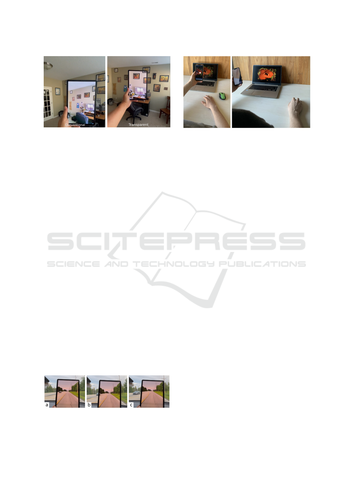
Figure 6: Comparison between a conventional AR display
(left) and our transparent display based on the distant geom-
etry assumption (right). Although the desk is less than 2m
away, there is little visualization discontinuity between the
display and its surroundings.
4.1 Study Design
General Procedure. The essence of our user study
procedure is to show the participant an annotation on
the AR display, and then to ask the participant to in-
dicate the location of the annotation in the real world.
An important concern is to record the real world loca-
tion indicated by the participant accurately, such that
it can be compared with the known correct location
of the annotation. To achieve this, we designed a pro-
cedure where the participant is seated in front of a
laptop (Fig. 8); the transparent AR display is imple-
mented with a phone (left); the participant holds the
AR display in their hand and looks through it at a lap-
top screen which displays an image; the AR display
annotates the image shown by the laptop with a dot;
the annotation is shown for 2s; once the annotation
disappears, the participant is asked to indicate the po-
sition of the annotation on the laptop screen using the
mouse; this way, the location indicated by the partic-
ipant can be recorded accurately by the laptop. The
display transparency is computed in the planar proxy
mode, leveraging the planarity of the laptop screen.
Participants. We recruited 17 participants from
a high school, including students and teachers, with
ages between 16 and 52, 12 male and 5 female. The
study was approved by the institution, and was con-
ducted with informed consent from participants or
their legal guardians. We asked participants to rate
their prior experience with AR applications; 4 partici-
Figure 7: Transparent display frames with passing car mov-
ing from being seen on transparent display (a) to being seen
directly (c).
Figure 8: Experimental setup: (left) annotation (white
dot, enlarged here for illustration clarity) shown to partic-
ipant through our transparent AR display implemented with
handheld phone, and (right) participant indicating the anno-
tation location using mouse.
pants rated their AR experience as high, 6 as medium,
2 as low, and 5 as none. The participant AR experi-
ence was related to the use of applications such as
Pok
´
emon GO and Snapchat.
Conditions (Independent Variable). The study
had two conditions. In a first, control condition (CC),
the AR display showed the annotation directly on
the video frame captured by the phone’s back-facing
camera (i.e., conventional AR display). In a second,
experimental condition (EC), the AR display showed
the annotation with improved transparency, based on
tracking the planar image displayed on the worksta-
tion screen (i.e., our transparent AR display).
Implementation Details. We implemented the
AR display as an Android app deployed on a
HUAWEI Mate20 lite phone. The phone was held
in portrait mode. The phone screen is 14.7cm tall and
6.4cm wide. The application was developed in Unity
version 2020.3.2 using AR Foundation, which builds
upon Google’s AR Core.
The EC condition was implemented with a frag-
ment shader that looks up each AR display pixel in the
original frame using conventional projective texture
mapping between the user view and the back-facing
camera view, which are connected by the homogra-
phy defined by the tracked laptop image plane. The
annotation location was mapped using a similar pro-
jective texture mapping operation that unprojects the
original frame coordinates to 3D on the tracked im-
age plane and then projects the 3D position onto the
AR display. The CC condition was implemented with
a fragment shader that places the dot directly on the
original frame, leveraging the tracked laptop image
plane.
For the planar proxy mode, the plane is tracked
up to a constant of proportionality, as is always the
case in passive computer vision algorithms. In other
words, the transparency effect works the same for a
Improved Directional Guidance with Transparent AR Displays
35
plane that is twice as big and is twice as far away.
There are no parameters that need to be set.
The laptop displays the image which is annotated
by the AR display, and it runs a simple data collection
application that records the mouse clicks for every an-
notation localization task.
Tasks. Each participant performed 10 annotation
localization tasks for the CC condition and 10 for the
EC condition (within-subject design). The condition
order was randomized. As described above, the anno-
tation localization task shows the user an annotation
on the phone anchored to the image displayed by the
laptop, and then asks the user to indicate the location
of the annotation on the laptop screen using the lap-
top’s mouse.
Dependent Variable. For each task, the worksta-
tion measured the annotation localization error as the
distance in pixels between the correct and the partici-
pant indicated locations.
Data Analysis Procedure. The localization er-
rors of the two conditions were compared using a de-
pendent T-Test, as required by our within-subject de-
sign, and using effect sizes quantified with Cohen’s d
(Cohen, 1988). We used the SPSS statistical software
package.
4.2 Study Results and Discussion
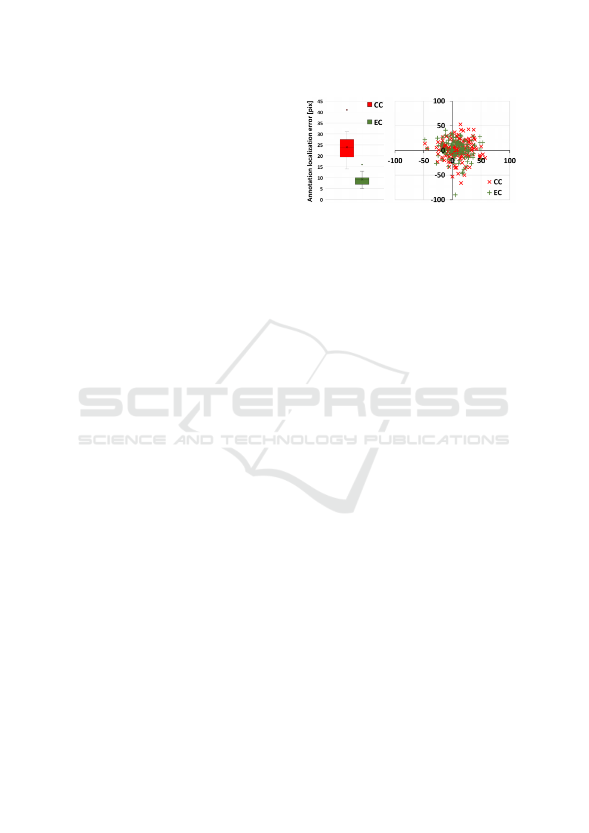
Fig. 9, left, shows the box plots of the localization
error, for each of the two conditions. The mean lo-
calization error in pixels was 23.94±6.35 for CC and
9.24 ± 2.68 for EC. Using the size of the image on
screen and the distance from the participant to the
screen, these localization errors correspond to angu-
lar errors of 0.46 ± 0.12
◦
for CC and 0.18 ± 0.05
◦
for
EC. The mean error difference CC-EC was 14.71 ±
4.90pix, and 0.28 ± 0.07
◦
. The scatter plot in Fig. 9,
right, illustrates the actual participant click locations
around the true annotation position, in pixels–the er-
rors appear uniformly distributed around the correct
location, with a higher error magnitude for CC.
The four assumptions of the dependent T-Test
hold: our dependent variable is continuous, there are
two dependent groups, there were no significant out-
liers in the differences between the two groups, and
the differences in the dependent variable between the
two related groups are normally distributed, which
we verified (p = 0.520) using the Shapiro-Wilk test
(Shapiro and Wilk, 1965). The dependent T-Test
shows that the experimental condition localization er-
rors are significantly lower than the control condition
errors (t(16) = 12.384, p < 0.0005). We measured the
effect size using Cohen’s d, which revealed a Huge
(Sawilowsky, 2009) effect size (d = 3.004).
Figure 9: Box and scatter plots of annotation localization
errors for the control (CC) and experimental (EC) condi-
tions.
The study results indicate a significant advantage
for our transparent display in terms of annotation lo-
calization accuracy, compared to the conventional AR
display. Our transparent display places the annotation
at a more accurate location in the user’s field of view,
and the user can extrapolate its location from the dis-
play to the real world with significantly higher accu-
racy. On the other hand, the conventional AR display
requires the user to estimate the position of the an-
notation in the real world based on memorized land-
marks, which is challenging.
We note that the flower image used in our study
(Fig. 8) is not repetitive and it does have salient
features, which makes the annotation localization
tractable for the conventional AR display. Annota-
tion localization can become more difficult with the
conventional AR display for texture-less or repetitive
images. For example, the user is unlikely to find a
specific window in a fac¸ade using the conventional
display, as all windows look the same (Fig. 1a).
5 CONCLUSIONS AND FUTURE
WORK
We have described an AR display with good trans-
parency accuracy for a variety of scenes with com-
plex and dynamic geometry. Transparency accuracy
is robust to deviations of the user viewpoint away
from the assumed default position, and to non-planar
or close-by scene geometry. A study shows that our
transparent display lets users locate annotations in
the real world with significantly higher accuracy, by
eliminating the landmark memorization and annota-
tion remapping tasks of conventional AR displays.
The handheld display AR interface makes use of
devices such as phones and computer tablets, which
have many of the AR required qualities, such as a
high resolution back-facing camera, a high resolution
display, and a compact form factor. However, these
devices were not designed for AR, and they have lim-
GRAPP 2023 - 18th International Conference on Computer Graphics Theory and Applications
36

itations that our AR displays inherit. One is that the
camera is typically placed at the corner and not at the
center of the display, which translates to more miss-
ing pixels for the planar geometry transparent AR dis-
play when the scene geometry is close (Fig. 1h). A
second limitation is the latency between frame cap-
ture and display. Whereas this is acceptable when the
display is used as a camera viewfinder, the latency is
problematic in AR where it causes annotations to drift
as the display moves. In our specific context, latency
makes the transparency accuracy lag when the display
moves abruptly (see driving sequence in video ac-
companying our paper). Future work could examine
leveraging motion prediction or low latency sensors
such as the display’s accelerometers to try to alleviate
this latency, but the more robust solution is likely to
require that the latency be eliminated by phone and
tablet manufacturers.
In its current implementation, the user is asked to
choose between the two modes: planar proxy or dis-
tant geometry. For the planar proxy mode, the system
assumes that it sees only plane. Future work could
look into actively searching for planes and for switch-
ing between the two modes on the fly, as needed,
without user intervention. Our display transparency
works best when the user head position is indeed at
the default distance above the center of the display.
Holding this position reasonably well is possible, as
shown by the video and by the results of our study.
Future work could examine giving the user cues about
their head position, which is easier to do than full head
tracking.
Another limitation that our approach inherits from
the conventional AR display interface is the lack of
depth cues. Whereas with a truly transparent dis-
play the scene is seen stereoscopically, and therefore
it appears at the correct depth, the transparent display
provides a monoscopic view of the scene, at a fixed,
nearby distance. Even though one has to change focus
from the nearby display to the scene, our study par-
ticipants have been able to extrapolate the direction
of the annotation to map it to the scene more accu-
rately when using our transparent display, compared
to when using the conventional AR display, which is
also void of depth cues.
Our approach for improving AR display trans-
parency has the advantage of working on any phone
or tablet with a back-facing camera, without requiring
depth acquisition or user tracking capabilities. Fur-
thermore, the computational cost of the homography
is low, so our approach is compatible even with low
end devices. Our approach brings an infrastructure-
level contribution that is ready to be integrated in vir-
tually all AR applications, where it promises the ben-
efit of improved directional guidance.
ACKNOWLEDGEMENTS
We thank our participants for their essential role in
validating our work. We thank Andreas Schuker and
Susanne Goedicke for all their support. We thank the
anonymous reviewers for their help with improving
this manuscript.
REFERENCES
Andersen, D., Popescu, V., Lin, C., Cabrera, M. E., Shang-
havi, A., and Wachs, J. (2016). A hand-held, self-
contained simulated transparent display. In 2016 IEEE
International Symposium on Mixed and Augmented
Reality (ISMAR-Adjunct), pages 96–101.
Bari
ˇ
cevi
´
c, D., H
¨
ollerer, T., Sen, P., and Turk, M. (2017).
User-perspective ar magic lens from gradient-based
ibr and semi-dense stereo. IEEE Transactions on Visu-
alization and Computer Graphics, 23(7):1838–1851.
Bari
ˇ
cevi
´
c, D., Lee, C., Turk, M., H
¨
ollerer, T., and Bow-
man, D. A. (2012). A hand-held ar magic lens with
user-perspective rendering. In 2012 IEEE Interna-
tional Symposium on Mixed and Augmented Reality
(ISMAR), pages 197–206.
Borsoi, R. A. and Costa, G. H. (2018). On the perfor-
mance and implementation of parallax free video see-
through displays. IEEE Transactions on Visualization
and Computer Graphics, 24(6):2011–2022.
Cohen, J. (1988). Statistical power analysis for the behav-
ioral sciences. Hillsdale, N.J. : L. Erlbaum Associates.
Grubert, J., Seichter, H., and Schmalstieg, D. (2014).
[poster] towards user perspective augmented reality
for public displays. In 2014 IEEE International Sym-
posium on Mixed and Augmented Reality (ISMAR),
pages 267–268.
Hill, A., Schiefer, J., Wilson, J., Davidson, B., Gandy, M.,
and MacIntyre, B. (2011). Virtual transparency: In-
troducing parallax view into video see-through ar. In
2011 10th IEEE International Symposium on Mixed
and Augmented Reality, pages 239–240.
Matsuda, Y., Shibata, F., Kimura, A., and Tamura, H.
(2013). Poster: Creating a user-specific perspec-
tive view for mobile mixed reality systems on smart-
phones. In 2013 IEEE Symposium on 3D User Inter-
faces (3DUI), pages 157–158.
Mohr, P., Tatzgern, M., Grubert, J., Schmalstieg, D., and
Kalkofen, D. (2017). Adaptive user perspective ren-
dering for handheld augmented reality. In 2017 IEEE
Symposium on 3D User Interfaces (3DUI), pages
176–181.
Pucihar, K., Coulton, P., and Alexander, J. (2013). Eval-
uating dual-view perceptual issues in handheld aug-
mented reality: Device vs. user perspective rendering.
pages 381–388.
Improved Directional Guidance with Transparent AR Displays
37

Samini, A. and Palmerius, K. (2014). A perspective geom-
etry approach to user-perspective rendering in hand-
held video see-through augmented reality.
Sawilowsky, S. S. (2009). New effect size rules of thumb. In
Journal of Modern Applied Statistical Methods, vol-
ume 8, pages 597–599.
Shapiro, S. S. and Wilk, M. B. (1965). An analysis
of variance test for normality (complete samples).
Biometrika, 52(3/4):591–611.
Tomioka, M., Ikeda, S., and Sato, K. (2013). Approximated
user-perspective rendering in tablet-based augmented
reality. In 2013 IEEE International Symposium on
Mixed and Augmented Reality (ISMAR), pages 21–28.
Uchida, H. and Komuro, T. (2013). Geometrically consis-
tent mobile ar for 3d interaction. pages 229–230.
Yoshida, T., Kuroki, S., Nii, H., Kawakami, N., and Tachi,
S. (2008). Arscope. page 4.
Zhang, E., Saito, H., and de Sorbier, F. (2013). From
smartphone to virtual window. In 2013 IEEE Inter-
national Conference on Multimedia and Expo Work-
shops (ICMEW), pages 1–6.
GRAPP 2023 - 18th International Conference on Computer Graphics Theory and Applications
38
