
Real-Time Physics-Based Mesh Deformation with Haptic Feedback and
Material Anisotropy
Avirup Mandal
1 a
, Parag Chaudhuri
2 b
and Subhasis Chaudhuri
1 c
1
Department of Electrical Engineering, IIT Bombay, Powai, Mumbai, India
2
Department of Computer Science and Engineering, IIT Bombay, Powai, Mumbai, India
Keywords:
Virtual Sculpting, Haptic Feedback, Wetting, Deformation.
Abstract:
We present a real-time, physics-based framework to simulate porous, deformable materials and interac-
tive tools with haptic feedback that can reshape them. In order to allow the material to be moulded non-
homogeneously, we propose an algorithm to change the material properties of the object depending on
its water content. To enable stable visual and haptic feedback at interactive rates, we implement a multi-
resolution, multi-timescale solution. We test our model for physical consistency, accuracy, interactivity and
appeal through a user study and quantitative performance evaluation.
1 INTRODUCTION
Traditionally simulated virtual shape editing tools of-
fer a visual rendering of the object but entirely miss
the haptic aspect of it. Moreover, many of these
tools edit shapes in a purely geometric approach and
thus, are not physically accurate (De Goes and James,
2017). In this paper, we present a real-time, stable, in-
teractive, physics-based deformation framework with
faithful haptic feedback. We implement it as a multi-
resolution solution to be able to handle deformation of
high-resolution meshes. Our method works at mul-
tiple timescales to synchronise the haptic and visual
modes of interaction.
In the real world, an artist deforms a lump of clay
to sculpt it into a model. Adding water to the clay
makes it malleable, which in turn helps to reshape
parts of the same model differently. Our method
allows a user to perform these operations virtually
while receiving the appropriate haptic feedback for
the same. The major contributions of the work pre-
sented in this paper are as follows.
• Develop a stable, interactive, physics-based hap-
tic and visual simulation framework, with a multi-
resolution implementation.
• Develop a physically valid model for deformable,
porous soft volumetric objects.
a
https://orcid.org/0000-0002-2322-4440
b
https://orcid.org/0000-0002-1706-5703
c
https://orcid.org/0000-0002-1680-0016
• Modeling of objects with anisotropic elasticity
when parts of the material are made wet with
an interactive wetting tool. This allows the user
to deform the object differently in different parts
while applying the same force.
The rest of the paper is organized as follows. After
presenting a discussion on the related works, we de-
tail our simulation of variable elasticity produced by
material wetting. Next, we present full technical de-
tails of our haptic rendering solution for faithful force
feedback at interactive rates. Finally, we present qual-
itative, quantitative and user study results generated
using our framework.
2 RELATED WORK
In this section, we review the methods present in
the literature that are closely related to our work.
One of the most popular approaches to modelling
deformable objects is the Finite Element Method
(FEM). O’Brien (O’Brien et al., 2002), M
¨
uller et
al. (M
¨
uller and Gross, 2004) used FEM on tetrahe-
dral meshes with linear elasticity to model deformable
objects including plasticity and fracture. Non-linear
elasticity with the large plastic flow is rendered in
more recent works by Bargteil et al. (Bargteil et al.,
2007), Irving et al. (Irving et al., 2004).
Fluid flow and material wetting is a well-studied
subject in material physics (Bear, 1972) (Scriven,
Mandal, A., Chaudhuri, P. and Chaudhuri, S.
Real-Time Physics-Based Mesh Deformation with Haptic Feedback and Material Anisotropy.
DOI: 10.5220/0011611800003417
In Proceedings of the 18th International Joint Conference on Computer Vision, Imaging and Computer Graphics Theory and Applications (VISIGRAPP 2023) - Volume 1: GRAPP, pages
153-161
ISBN: 978-989-758-634-7; ISSN: 2184-4321
Copyright
c
2023 by SCITEPRESS – Science and Technology Publications, Lda. Under CC license (CC BY-NC-ND 4.0)
153

1994). In computer graphics, work by Patkar et
al. (Patkar and Chaudhuri, 2013) offers a geometri-
cally modelled solution to the absorption, diffusion
and dripping of water in porous materials. In more
recent work (Fei et al., 2018), the wetting of different
kinds of clothes is explored. The change of material
properties due to fluid absorption is well investigated
in material science (Yoon and Cowin, 2009) (Schraad,
2014). Here the authors hypothesize a mathematical
relationship between object elasticity with fluid con-
tent and verify their hypothesis with empirical results.
Zilles and Salisbury (Zilles and Salisbury, 1995)
present God Object-based rendering where a god ob-
ject is constrained to stay on the surface of the mesh
object while a haptic proxy penetrates into the ob-
ject and the difference of their acceleration generates
haptic feedback. Ortega et al. (Ortega et al., 2007)
extended it to all six degrees of freedom. Another
broad category of haptic force rendering is penalty-
based rendering (Barbi
ˇ
c and James, 2009) (Otaduy
and Lin, 2005) (McNeely et al., 1999). Here (Xu
and Barbi
ˇ
c, 2017), the colliding objects penetrate
each other and force feedback is rendered depending
on the depth of penetration. Discrete penalty-based
rendering suffers from discontinuous and jerky force
feedback when the contact stiffness is high. These
problems are circumvented using continuous colli-
sion detection (Tang et al., 2012) (Xu and Barbi
ˇ
c,
2017). Even though constrained-based methods are
slightly more robust against the pop-through effect
of the proxy, we opted for the continuous penalty-
based method for our haptic feedback as it produces
smoother force feedback (Xu and Barbi
ˇ
c, 2017).
Notable works in virtual shape editing include
methods presented in (Blanch et al., 2004) (Chen and
Sun, 2002) which build a rigid model using a small
cubic grid-based field. These methods do not emulate
physically accurate material behaviour and are time-
consuming. In the works (Gunn, 2006) (Dachille
et al., 1999), the authors present frameworks that
deform polygonal mesh based on mass-spring-based
models in a strictly geometric way. The key draw-
back of all these existing works is that none of them
preserves physical plausibility. Moreover, the haptic
feedback provided in all these works is based on dis-
crete collision handling which suffers from jitters. We
use continuous collision-based smooth haptic feed-
back to tackle this problem. The need for physically
realistic virtual sculpting has been explored recently
by De Goes et al. (De Goes and James, 2017). Using
Kelvinlets (fundamental solutions of linear elasticity
for singular loads), they render the accurate mesh de-
formation in real time, but their work lacks the aspects
of haptic feedback.
ζ
Θ, t=0
u
Θ, t=t'
x
Figure 1: Material (left) coordinate to world (right) coordi-
nate.
In more recent work (Mandal et al., 2022) we find
a method for cutting meshes with accurate physics-
based simulation and haptic feedback. Our work com-
plements this work, as we present a method to deform
the mesh while simulating the physics of wetting and
consequent material anisotropy.
We present a framework to efficiently reshape
meshes in a physically realistic manner with smooth
haptic feedback. Additionally, real-life objects have
anisotropic elasticity that can be modelled implicitly
using wetting in our framework.
3 DEFORMABLE POROUS
OBJECTS
In this section, we will briefly describe the modelling
of a deformable object using Cauchy’s linear strain
model and then discuss how we model the change of
elasticity due to the wetting of the object.
We use a standard finite element discretization to
solve the governing differential equations of a de-
forming object (M
¨
uller and Gross, 2004) (Erleben
et al., 2005). Let Θ ∈ R
3
be a three-dimensional do-
main which is discretized into a mesh of n
tet
tetrahe-
dra. The number of nodes shared by these tetrahedral
elements is n
v
. As shown in Figure 1, a displacement
function, u : Θ× [0,∞) −→ R
3
is a mapping of a ma-
terial point ζ ∈ Θ at time t ∈ [0,∞) to its deformed
location x in the world space.
u(ζ,t) =
n
v
∑
i=1
N
i
(ζ)u
i
(t), ∀ζ ∈ Θ (1)
where N(ζ) and u
i
(t) represents the shape function
and displacement vector at the node i respectively.
The system dynamics of a deformed object can then
be written in Lagrange’s form as
M
¨
u + f
int
= f
ext
, u =
u
T
1
...u
T
n
v
T
(2)
where M, f
ext
, f
int
are respectively mass matrix, exter-
nal and internal element force vector of the full sys-
tem. Plastic flow is also enforced in this model when
the strain exceeds a yield threshold as presented in the
work by M
¨
uller et al. (M
¨
uller and Gross, 2004).
For wetting the material, we follow the method
proposed in (Patkar and Chaudhuri, 2013) barring the
GRAPP 2023 - 18th International Conference on Computer Graphics Theory and Applications
154

dripping part of the algorithm that reduces the fluid
content in the object. Once collision occurs between
the wetting tool in our framework and the boundary of
the tetrahedral mesh, the fluid content in the tetrahe-
drons in contact with the tool increases in incremental
steps till the saturation value becomes one. The sat-
uration of a tetrahedron is defined as S
w
= m
w
/V
e
.
Here m
w
is the mass of water absorbed and V
e
is the
volume of the tetrahedron. After the absorption of
fluid, diffusion happens between any two neighbour-
ing tetrahedra depending on the saturation gradient
between them (Patkar and Chaudhuri, 2013). A dry-
ing tool is provided whose action is complementary
to the wetting one.
3.1 Variable Elasticity
In order to formulate a relationship between fluid con-
tent and elasticity of the material we followed the line
of thought presented in (Yoon and Cowin, 2009). To
the best of our knowledge, our framework is the first
use of this method in an interactive, real-time setting.
The Voigt upper bound on the elasticity tensor of a
solid-fluid mixture is given by
C
V
= (1 −φ)C
s
+ φC
w
(3)
where C
V
, C
s
and C
w
are the elasticity tensors of
the mixture, solid and fluid respectively. The quan-
tity φ denotes the fluid volume fraction in the solid.
The Reuss lower bound on the compliance tensor of a
solid-fluid mixture with any kind of solid and fluid is
given by
S
R
= (1 −φ)S
s
+ φS
w
(4)
where S
R
, S
s
and S
w
are the compliance tensors of the
mixture, solid and fluid respectively. The Voigt and
Reuss bounds together give the bound on the effective
elasticity tensor as
S
R
−1
≤ C
e f f
≤
C
V
(5)
Putting everything together, the effective compliance
tensor for the solid-fluid mixture with any kind of
solid and fluid is given by
S
e f f
=
h
1 + φ
Q
I
− P
I
−1
i
S
M
(6)
where Q
I
≡
C
M
− C
I
−1
C
M
, P
I
is the Eshelby ten-
sor (Eshelby, 1957), S
M
is the matrix compliance ten-
sor, C
M
is the matrix elasticity tensor and C
I
is the
inclusion elasticity tensor. For our framework, we as-
sume C
M
= C
s
, S
M
= S
s
and C
I
= C
w
. Using this
formulation we determine the effective elastic tensor
of a solid-fluid mixture system. We always use water
for fluid in our framework. As the change of elastic-
ity is dependent on the fraction of water content in
the tetrahedral element and water content is depen-
dent on the gradient of saturation, there is never any
abrupt change of elasticity in the model, thus main-
taining the stability of the system.
4 HAPTIC RENDERING
The model developed in the previous section for the
deformation of an object made of a porous material is
used in conjunction with haptic rendering. The hap-
tic interaction process with an object consists of the
following components:
• Continuous Collision Detection (CCD) between
the haptic proxy and tetrahedral simulation mesh.
• Continuous penalty-based haptic rendering while
deforming the mesh.
Haptic force feedback is performed on a volumetric
simulation mesh with tetrahedral elements. But to im-
prove the quality of visual rendering, we transfer the
deformation to a higher-resolution visualization sur-
face mesh. This is explained in Section 5.
t=1
t=0
t=t''
t=t'''
t=t'
p=q
p=q
p=q
p
p
q
p
p
p
q
q
q
Figure 2: Three contact times between colliding vertex ‘p’
and face ‘q’ are t
′
,t
′′
,t
′′′
. Penetration intervals are [t
′
,t
′′
] and
[t
′′
,1].
4.1 Continuous Collision Detection
We calculate continuous collision between the outer
boundary of the tetrahedral mesh and haptic proxy,
consisting of triangular face elements. We resolve
vertex-face and edge-edge collisions that arise when
two triangular face elements collide. In order to detect
a continuous collision, we begin by interpolating the
positions of each primitive i.e., vertex, edge and face
in the simulation time step, ∆t, normalized to [0,1].
Then a 3
rd
order equation in t is solved to find out
the number of collisions that occur between vertex-
face or edge-edge interactions during that simulation
time step. To detect the collisions fast, we used an
Axis Aligned Bounding Box for each of these primi-
tives and also followed a non-penetration filter-based
technique (Tang et al., 2010).
Real-Time Physics-Based Mesh Deformation with Haptic Feedback and Material Anisotropy
155

4.2 Haptic Rendering of Deformation
We classify the deformation of a mesh in two cate-
gories: (1) push deformation of mesh and (2) pull
deformation of mesh, both of which follow the same
principle except the applied force direction which is
inward for push and outward for pull. We detect col-
lision using CCD in each time step, ∆t, and then in-
tegrate over those particular time intervals when pen-
etration depth between collided primitives is positive,
implying that they are in a colliding state (Figure 2).
4.2.1 Vertex-Face Penalty Force
If a collision occurs between any vertex of the haptic
proxy and the triangular mesh boundary of the object
or vice-versa, then we calculate a penalty force (Tang
et al., 2012) as
I
V F
p
= k
v f
i<N
∑
i=0
Z
t
i
b
t
i
a
n
T
t
(p
t
− q
t
)n
t
dt (7)
Here k
v f
is a scalar stiffness constant. Time inter-
vals [t
i
a
,t
i
b
] ∈ [0,1] are called penetration time inter-
vals. These are defined as time while the vertex is in-
side the object mesh and i is the number of penetration
time intervals (See Figure 2). Moreover n
t
, p
t
and q
t
denote contact normal, the position of vertex and con-
tact point on boundary mesh respectively during ∆t.
The collision point on the triangular mesh can be ex-
pressed using barycentric coordinates of three vertices
of the mesh as q
t
= w
a
a
t
+ w
b
b
t
+ w
c
c
t
. Once we get
the penalty force I
V F
p
we apply it to the object mesh
−I
V F
p
for pulling
and apply a reaction force of the
same magnitude but opposite direction to the proxy.
4.2.2 Edge-Edge Penalty Force
Similar to vertex-face penalty force, we also calcu-
late penalty force I
EE
p
due to edge-edge collision. If a
collision occurs between the edge of the haptic proxy
mesh and the edge of the simulation mesh boundary
of the object, then the penalty force is calculated as
I
EE
p
= k
ee
i<N
∑
i=0
Z
t
i
b
t
i
a
n
T
E
t
(p
t
− q
t
)n
E
t
dt (8)
Here k
ee
is a scalar stiffness constant.
4.2.3 Clay-like Behaviour
While deforming the object we want to replicate a
clay-like behaviour in our model, i.e., the object
should be malleable near the point where an exter-
nal force is applied but the movement of the whole
structure of the object should be negligible due to this
B
A
C
D
E
F
Volumetric Simulation
Mesh (low res.)
Surface Visualization
Mesh (high res.)
p
B
A
E
F
p
C
D
1. Deform the Simulation Mesh
2. Update the
Visualization Mesh
Figure 3: Multi-resolution, multi-timescale deformation.
external force. To this end, we define a kernel func-
tion G
d
in Equation 9 around the position of the hap-
tic proxy. The velocities of the object mesh are scaled
with the weights of the kernel. If r = ||x − x
c
||
2
, then,
G
d
(x) =
1
1 + k
1
r
if r < R
D
1
1 + k
1
r + exp(k
2
r)
if r ≥ R
D
(9)
where k
1
, k
2
are stiffness constants, x
c
denotes the po-
sition of haptic proxy and || · ||
2
denotes the l
2
norm.
R
D
is the influence radius of the damping kernel. As a
result, velocities of points further away from the hap-
tic proxy are more damped than closer points.
5 MULTI-RESOLUTION
FRAMEWORK
Physics-based simulation is computationally expen-
sive and cannot be performed on extremely high-
resolution meshes at interactive rates. However, vi-
sual fidelity suffers a lot when low-resolution meshes
are used. On the other hand, haptic fidelity requires
simulations to run at very high frame rates. Our
framework allows us to find common ground between
all these disparate goals.
Our simulation runs on a coarse, low-resolution
volumetric mesh with tetrahedral elements that en-
closes a high-resolution surface mesh with triangle el-
ements like a cage. As shown in Figure 3, the vertices
of the surface mesh are expressed in the local space
of the simulation mesh using barycentric coordinates.
When the simulation mesh is deformed, the barycen-
tric coordinates of the surface mesh vertices in the
local space of the simulation mesh do not change.
This lets us calculate new coordinates of the surface
mesh vertices in a global coordinate system. Similar
ideas can be found in (Ju et al., 2005) (Chuhua Xian
et al., 2009). In Figure 4 two high-resolution sur-
face meshes, T-Rex (left) & Panther (right), and their
corresponding low-resolution volumetric simulation
meshes are depicted. Any manipulation performed on
the simulation mesh gets transferred to the visualiza-
tion surface mesh using a weight kernel. This sets up
the multi-resolution component of our framework.
GRAPP 2023 - 18th International Conference on Computer Graphics Theory and Applications
156
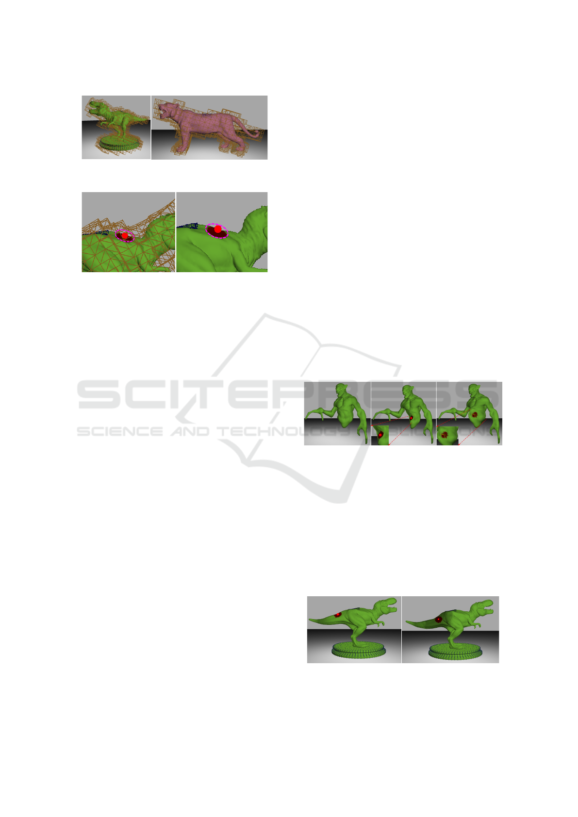
Figure 4: Surface visualization mesh embedded inside vol-
umetric simulation mesh: T-Rex (left) and Panther (right).
Figure 5: A deformation tool is colliding with the simu-
lation mesh (left). The circled colour gradient indicates the
region of deformation on the visualization mesh. The defor-
mation is projected onto the surface mesh for visualization
(right).
When a deformation (push/pull) tool collides with
the outer surface of the tetrahedral simulation mesh,
we visualize it by projecting a region with a colour
gradient on the surface mesh to denote the deforma-
tion region (Figure 5 left). The deformations are per-
formed on the simulation mesh. Using barycentric
coordinates this deformation is then transferred to the
surface mesh for visualization (Figure 5 right).
During wetting, any node of secondary mesh gets
the same saturation value as the tetrahedron which
contains it.
6 MULTI-TIMESCALE
FEEDBACK
For smooth haptic force feedback, a minimum refresh
rate of 1000 frames/sec is required. On the other
hand for smooth visual feedback, a refresh rate of
60 frames/sec is sufficient. To achieve both these re-
quirements, the whole simulation is run in two distinct
threads. On one thread, physical simulations along
with graphics rendering are performed while another
thread is used for rendering haptic feedback. We have
kept the haptic thread running at 1000 frames/sec all
time using HAPI API which samples the haptic force
feedback at the required rate. The refresh rate of the
visual thread varies from 70 − 900 frames/sec, de-
pending on the underlying object mesh. So, the hap-
tic thread keeps rendering the same old force feed-
back at the higher frame rate, until it gets a force
update from the visual thread which runs at a much
slower rate. The synchronization between the two
threads is obtained implicitly due to the rapid update
rate of the haptic thread, instead of using a blocking,
explicit synchronization construct. Because of this
construct, our framework can work on high-resolution
mesh models with intricate details without degrading
the quality of haptic experience.
7 RESULTS
In this section, we present results that help evalu-
ate the performance of our mesh reshaping solution.
First, we show the results of deforming the object
mesh. We then demonstrate the effect of wetting the
material. Further, we present the results of a user
study, conducted to evaluate the qualitative perfor-
mance of our solution. A quantitative evaluation of
our framework is also conducted to affirm that we sat-
isfy real-time interaction constraints.
All the results presented here are obtained on a
system with an Intel i7-4770K octa-core processor at
3.5GHz, 32GB RAM, a single Nvidia Geforce GTX
Titan GPU with 5860 MB of graphics memory and a
6-DOF haptic device from Geomagic Touch.
Figure 6: Illustration of the original model (left), the in-
teraction of the push tool with the model (middle) and the
interaction of the pull tool with the model (right).
As shown in Figures 6, whenever a haptic proxy
touches the simulation mesh, a colour gradient gets
projected on the surface of the mesh near proxy within
radius R
D
as mentioned in Equation 9. This helps the
user to get a better perception of the deformation re-
gion. In Figure 6, a zombie object mesh with a push
deformation (middle) and a pull deformation (right) is
shown. For push deformation, the mesh collapses and
bulging takes place for pull deformation.
Figure 7: Deforming a dry (left) and partially wet (right)
T-Rex model with a push haptic tool.
Real-Time Physics-Based Mesh Deformation with Haptic Feedback and Material Anisotropy
157

Figure 8: Illustration of haptic feedback force while inter-
acting with dry and wet object. As expected the force is
much less for the wet case.
Using a wetting tool we can wet material by trans-
fer of fluid. Any vertex of the surface mesh gets the
same saturation value as the tetrahedron from the sim-
ulation mesh that contains the vertex. In Figure 7 a
user is shown interacting with a dry and a partially
wet T-Rex model. Except for the effect of wetting on
elasticity, the other material properties of the object
mesh and the area where the user interacts remain the
same in both cases. The haptic feedback force during
this interaction is shown in Figure 8. The perceptive
change of haptic feedback force after fluid absorption
is evident from the plot which indicates that the wet
model offers less resistance compared to the dry one.
Moreover, as shown in Figure 7, the wet portion of the
mesh exhibits more deformation due to the change in
the material property after water absorption.
In Figure 9, we present a T-Rex model reshaped
using our framework.
Figure 9: Original (left) and deformed (right) T-Rex model.
7.1 User Study
Two different user studies were conducted to evaluate
the subjective quality of our virtual mesh reshaping
solution compared to real-world experience.
• Haptics-Visual Feedback Study to analyse the
effect of haptics and visual feedback in virtual
mesh reshaping. We perform an ANOVA analy-
sis for this study.
• Double Stimulus Comparison Study to evaluate
how close the virtual sculpting experience is com-
pared to real-world sculpting.
20 subjects in the age group 20 − 35 years partici-
pated in the user study. All the participants confirmed
that they are not differently abled either physically or
Table 1: p-value for ANOVA study.
Compared strategies p-value
1 vs 2 0.00070
1 vs 3 0.00001
mentally. None of the participants had any prior ex-
perience with a haptic setup.
As the subjects participating in our experiment
were not familiar with any kind of haptic setup, we
first trained them to use a haptic device. For that
purpose, we used a model scene provided with Ge-
omagic Touch haptic device. The scene contains two
boxes and using a haptic proxy, a user can move or
lift those boxes while getting appropriate force feed-
back. We ask each of the subjects to move and lift the
boxes with the haptic proxy repeatedly until he/she
feels comfortable handling a haptic device.
7.1.1 Haptics-Visual Feedback Study
The Analysis of Variance (ANOVA) (Fisher, 1954) is
a commonly used tool to evaluate whether the differ-
ences between groups of data are statistically signifi-
cant. ANOVA is used in our work here to determine
the importance and effectiveness of both visual and
haptic feedback in a virtual mesh editing framework.
The participants are asked to perform virtual defor-
mation and wetting of a mesh in the following manner
and rate their experience on a scale of 1 (very poor) to
5 (very good) for each case.
• Strategy 1 - Visual On & Haptics On: Perform
both the virtual deformation and wetting opera-
tions with both visual and haptic feedback.
• Strategy 2 - Visual On & Haptics Off: Per-
form both the virtual deformation and wetting op-
erations with visual feedback but without haptic
feedback.
• Strategy 3 - Visual Off & Haptics On: Per-
form both the virtual deformation and wetting op-
erations without visual feedback but with haptic
feedback.
By ”without visual feedback” we do not denote a
complete absence of the virtual scene. It means that
the effect of the deformation and wetting operations
are not rendered on the high-resolution visualization
mesh. All the operations are performed only on the
outer cage mesh.
The null hypothesis in ANOVA suggests that all
groups are random samples from the same popula-
tion, which in our work means that all the there strate-
gies are equally effective. Thus, any observed dif-
ference between them is due to random noise. The
p-value defines the probability of obtaining results at
GRAPP 2023 - 18th International Conference on Computer Graphics Theory and Applications
158
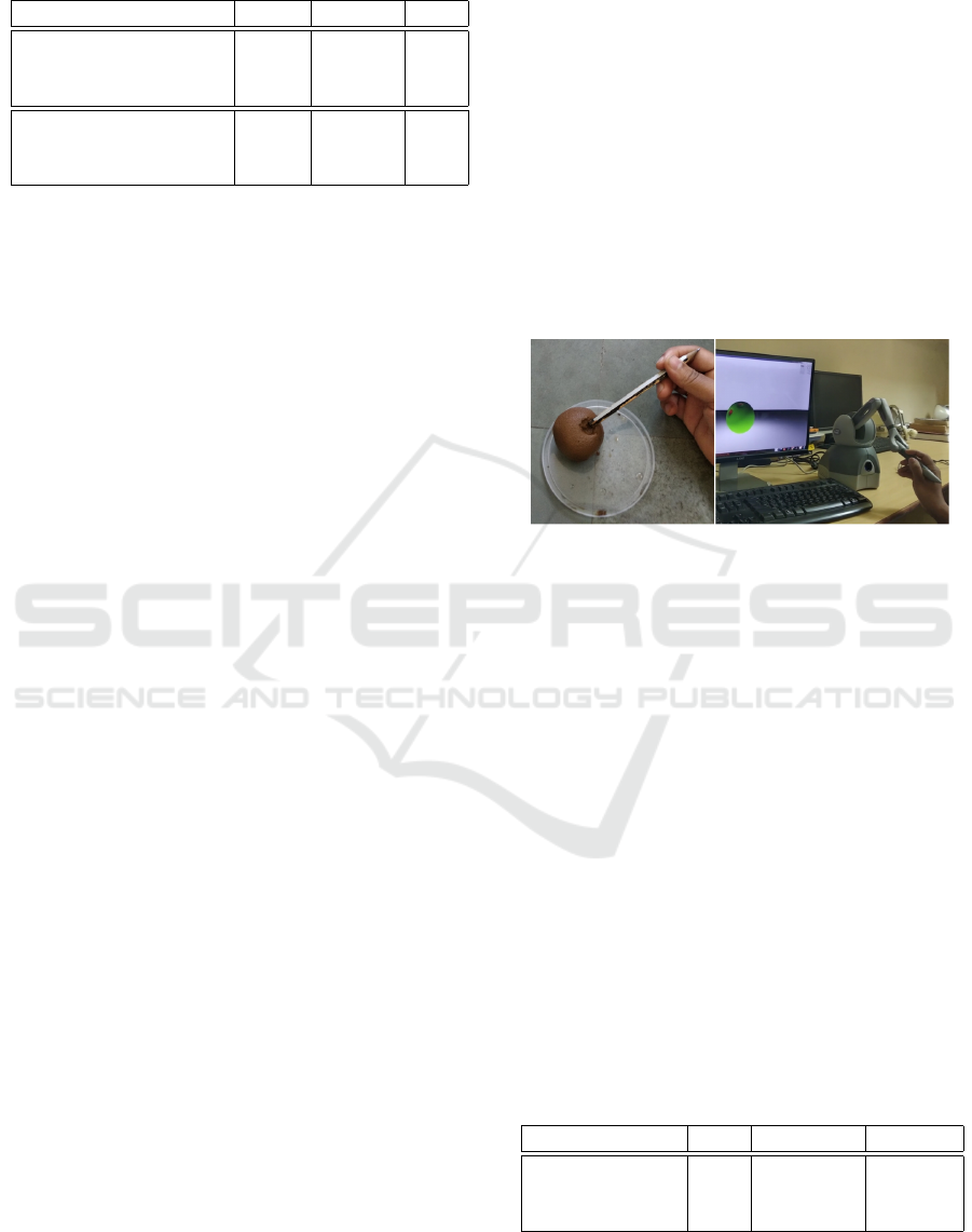
Table 2: Mean and standard deviation of user feedback (1 -
very poor to 5 - very good).
Parameter Mean Median Std
Visual On, Haptics On 4.63 4.71 0.26
Visual On, Haptics Off 4.12 4.27 0.28
Visual Off, Haptics On 2.62 2.75 0.51
Realistic 4.61 4.65 0.35
Visual-haptic sync 4.72 4.90 0.25
Physical consistency 4.48 4.50 0.29
least as extreme as the observed results of a statisti-
cal hypothesis test, assuming that the null hypothesis
is correct. Thus, if the p-value falls below a certain
threshold, the null hypothesis is considered invalid. In
our study, we use p-value of 0.05, which is a widely
accepted choice. The p-value (see Table 1) for Strat-
egy 1 vs Strategy 2 is 0.00070 < 0.05, which rejects
the null hypothesis. From the top half of Table 2, the
higher mean and median score for Strategy 1 com-
pared to Strategy 2 denotes that user experience for
virtual sculpting improves when haptic feedback is
on. Similarly, the p-value for Strategy 1 vs Strategy
3 is 0.00001 < 0.05, which again rejects the null hy-
pothesis. The much higher mean and median score for
Strategy 1 compared to Strategy 3 proves that visual
feedback is very useful for a faithful user experience.
Finally, based on the previous results, we can
make the following observations.
Strategy 1 vs Strategy 2: According to the users’
rating, Strategy 1 is better than Strategy 2. It reveals
that if the visual feedback remains the same, turning
on the haptic feedback improves user experience.
Strategy 1 vs Strategy 3: We can observe from
the user ratings that Strategy 3 performs very poorly
compared to Strategy 1. This implies the importance
of appropriate visual feedback for our virtual mesh
editing framework. This closely resembles our real-
life experience too, where visual cues and motions are
most dominant among all the six sensory senses used
for perception.
7.1.2 Double Stimulus Comparison Study
We perform our subjective evaluation based on a dou-
ble stimulus comparison (Union, 2013) method. The
steps of the evaluation are as pointed out below.
• First Stimulus: We ask the subjects to mould a
ball of clay to any shape of their choice using their
hands and a pencil to get a feel of real-world shape
shaping.
• Second Stimulus: The subjects are then asked to
reshape object models virtually using our frame-
work with and without haptic feedback.
Our experimental setup is shown in Figure 10. A user
deforming a real clay sphere (left) and a virtual clay
sphere (right) is shown in the figure. After the ex-
periment is finished, the participants are asked to rate
their experience on a scale of 1 (very poor) to 5 (very
good) for the following parameters.
• Realistic: The users are asked to rate how close
is their experience compared to the real world.
• Visual-haptic Synchronization: The partici-
pants are asked if they experienced any delay be-
tween visual change and haptic force feedback.
• Physical Consistency: Consistency of the vi-
sual simulation of our framework with real-world
physical objects.
Figure 10: Comparing the experience of deforming a real
clay sphere on the left to the haptic feedback of deforming
a virtual clay sphere on the right.
The mean and standard deviation of the scores of
the user feedback opinions are listed in Table 2. The
ratings reflect highly realistic experiences with little
difference of opinion (low standard deviation).
7.2 Quantitative Evaluation
As mentioned earlier, in our multi-timescale frame-
work, the haptic thread updates at 1000 frames per
second for smooth interaction. Depending on the
model structure used, the frame rate of the visual ren-
dering thread varies between 70 and 900 frames per
second which is sufficient for smooth visual feedback.
Further, to speed up the interaction frame rate in the
graphics thread we parallelized the computations on
the GPU wherever possible, using Nvidia CUDA. The
interactive frame rates of different tools of our frame-
work are presented in Table 3.
Table 3: Average frame-rate for different tools.
Model #tet Push/Pull Wet/Dry
T-Rex 2.5k 71.3 792.6
Zombie 1.2k 87.9 863.7
Sphere/Cylinder 1.5k 85.9 841.1
Real-Time Physics-Based Mesh Deformation with Haptic Feedback and Material Anisotropy
159

8 CONCLUSION AND FUTURE
WORK
We present a novel approach for a stable, real-time
simulation framework for mesh reshaping, enhanced
with haptic feedback and physically accurate material
simulation. We devise solutions to numerous chal-
lenges like the wetting of materials and the conse-
quent simulation of variable elasticity and deformable
porous solid simulation. Finally, we evaluate the ap-
peal and interactivity of our solution via a user study
and a variety of simulation results. One of the ma-
jor limitations of our work is that it works only with
one initial mesh. There is no provision for adding
more meshes on top of the initial mesh and cannot
thus model the functionality of material deposition.
In future, we want to work in this direction.
REFERENCES
Barbi
ˇ
c, J. and James, D. L. (2009). Six-dof haptic ren-
dering of contact between geometrically complex re-
duced deformable models. In World Haptics 2009,
pages 393–394.
Bargteil, A. W., Wojtan, C., Hodgins, J. K., and Turk, G.
(2007). A finite element method for animating large
viscoplastic flow. ACM Trans. Graph., 26(3):16:1–
16:10.
Bear, J. (1972). Dynamics of fluids in porous media / Jacob
Bear. American Elsevier New York.
Blanch, R., Ferley, E., Cani, M.-P., and Gascuel, J.-D.
(2004). Non-realistic haptic feedback for virtual
sculpture. Technical Report RR-5090, INRIA.
Chen, H. and Sun, H. (2002). Real-time haptic sculpting in
virtual volume space. In Proceedings of VRST, pages
81–88. ACM.
Chuhua Xian, Hongwei Lin, and Shuming Gao (2009).
Automatic generation of coarse bounding cages from
dense meshes. In 2009 IEEE International Confer-
ence on Shape Modeling and Applications, pages 21–
27.
Dachille, IX, F., Qin, H., Kaufman, A., and El-Sana, J.
(1999). Haptic sculpting of dynamic surfaces. In Pro-
ceedings of I3D, pages 103–110.
De Goes, F. and James, D. L. (2017). Regularized kelvin-
lets: Sculpting brushes based on fundamental solu-
tions of elasticity. ACM Trans. Graph., 36(4):40:1–
40:11.
Erleben, K., Sporring, J., Henriksen, K., and Dohlman, K.
(2005). Physics-based Animation (Graphics Series).
Charles River Media, Inc.
Eshelby, J. D. (1957). The determination of the elastic field
of an ellipsoidal inclusion, and related problems. Pro-
ceedings of the Royal Society of London. Series A,
Mathematical and Physical Sciences, 241(1226):376–
396.
Fei, Y. R., Batty, C., Grinspun, E., and Zheng, C. (2018). A
multi-scale model for simulating liquid-fabric interac-
tions. ACM Trans. Graph., 37(4):51:1–51:16.
Fisher, R. A. (1954). Statistical methods for research work-
ers; 20th ed. Oliver and Boyd, Edinburgh.
Gunn, C. (2006). Collaborative virtual sculpting with haptic
feedback. Virtual Reality, 10(2):73–83.
Irving, G., Teran, J., and Fedkiw, R. (2004). Invertible finite
elements for robust simulation of large deformation.
In Proceedings of SCA, pages 131–140.
Ju, T., Schaefer, S., and Warren, J. (2005). Mean value coor-
dinates for closed triangular meshes. In SIGGRAPH,
page 561–566.
Mandal, A., Chaudhuri, P., and Chaudhuri, S. (2022). In-
teractive physics-based virtual sculpting with haptic
feedback. Proc. ACM Comput. Graph. Interact. Tech.,
5(1).
McNeely, W. A., Puterbaugh, K. D., and Troy, J. J. (1999).
Six degree-of-freedom haptic rendering using voxel
sampling. In Proceedings of the 26th Annual Con-
ference on Computer Graphics and Interactive Tech-
niques, SIGGRAPH ’99, pages 401–408.
M
¨
uller, M. and Gross, M. (2004). Interactive virtual mate-
rials. In Proceedings of Graphics Interface 2004, GI
’04, pages 239–246.
O’Brien, J. F., Bargteil, A. W., and Hodgins, J. K. (2002).
Graphical modeling and animation of ductile fracture.
ACM Trans. Graph., 21(3):291–294.
Ortega, M., Redon, S., and Coquillart, S. (2007). A six
degree-of-freedom god-object method for haptic dis-
play of rigid bodies with surface properties. IEEE
Transactions on Visualization and Computer Graph-
ics, 13(3):458–469.
Otaduy, M. A. and Lin, M. C. (2005). Stable and responsive
six-degree-of-freedom haptic manipulation using im-
plicit integration. In World Haptics Conference, pages
247–256.
Patkar, S. and Chaudhuri, P. (2013). Wetting of porous
solids. IEEE Transactions on Visualization and Com-
puter Graphics, 19(9):1592–1604.
Schraad, M. W. (2014). A Theoretical Approach to the Cou-
pled Fluid–Solid Physical Response of Porous and
Cellular Materials: Dynamics, chapter 6, pages 127–
152. John Wiley & Sons, Ltd.
Scriven, L. E. (1994). Porous media: Geometry and trans-
port by pierre m. adler, butterworth-heinemann, stone-
ham, ma, 1992, 544 pp. AIChE Journal, 40(2):380–
381.
Tang, M., Manocha, D., Otaduy, M. A., and Tong, R.
(2012). Continuous penalty forces. ACM Trans.
Graph., 31(4):107:1–107:9.
Tang, M., Manocha, D., and Tong, R. (2010). Fast
continuous collision detection using deforming non-
penetration filters. In Proceedings of I3D, pages 7–13.
ACM.
Union, I. T. (2013). ITU-R the double-stimulus continuous
quality-scale. https://www.itu.int/dms pubrec/itu-r/
rec/bt/R-REC-BT.500-13-201201-I!!PDF-E.pdf. Ac-
cessed: 2021-04-17.
GRAPP 2023 - 18th International Conference on Computer Graphics Theory and Applications
160

Xu, H. and Barbi
ˇ
c, J. (2017). 6-dof haptic rendering us-
ing continuous collision detection between points and
signed distance fields. IEEE Transactions on Haptics,
10(2):151–161.
Yoon, Y. J. and Cowin, S. C. (2009). The elastic moduli
estimation of the solid-water mixture. International
Journal of Solids and Structures, 46(3):527 – 533.
Zilles, C. B. and Salisbury, J. K. (1995). A constraint-based
god-object method for haptic display. In Proceedings
1995 IEEE/RSJ International Conference on Intelli-
gent Robots and Systems, volume 3, pages 146–151.
Real-Time Physics-Based Mesh Deformation with Haptic Feedback and Material Anisotropy
161
