
Hybrid Control Based on Backstepping Sliding Mode Control
for Flow Modulation of Electric Fuel Pump
Han Zhang
1
, Bin Wang
2a
, Zhifeng Ye
2
, Tengfei Ma
1
and Hongcheng Zhang
1
1
College of Energy and Power Engineering,
Nanjing University of Aeronautics and Astronautics, Nanjing 210016, China
2
Jiangsu Province Key Laboratory of Aerospace Power System,
Nanjing University of Aeronautics and Astronautics, Nanjing 210016, China
Keywords: Electric Fuel Pump, Flow Modulation, Hybrid Control, Fault-Tolerant.
Abstract: As the core component of more electric engine (MEE), electric fuel pump is composed of a permanent magnet
synchronous motor (PMSM) integrated with a high-pressure gear pump. Rotation speed is controlled by the
motor and the pump discharges the fuel with required amount into the engine combustor. How the speed
control system works largely determines the delivery flow rate of the pump, although delivery pressure can
disturb the flow rate as well. Hence, it must be capable of delivering the maximum needed flow at appropriate
pressure to obtain satisfactory nozzle spray and accurate fuel regulation. In order to improve modulation
performance of the electric fuel pump with all conditions accessible, a complete mathematical model of the
pump is built and the hybrid control strategy within the scope of whole operation is proposed, considering the
measured parameter of fuel flow as feedback. The control strategy consists of a feed-forward compensation
based on differential pressure and backstepping non-singular fast terminal sliding mode control with extend
state observer. Results show that the hybrid control strategy can meet the requirements of fuel flow regulation
for aeroengines including accuracy of wide range flow and quick response ability. Additionally, the
effectiveness of redundancy design is shown, which contributes to its reliability as an airborne component.
1 INTRODUCTION
The More Electric Engine, incorporating new
advances in motor/generators, active magnetic
bearings, power electronics and other electrical
technologies (Mohammadi et al., 2021; Wang et al.,
2021; McLoughlin et al., 2009), has attracted wide
attention with its excellent properties including
reduced specific fuel consumption, high thrust-
weight ratio, reliability, maintainability, and
environmental friendliness.
Nowadays, the main fuel pump of aero-engine
generally adopts a gear pump, which has the
advantages of large flow rate, compact configuration,
and high reliability (Morioka et al., 2013). It is a type
of constant displacement pump which delivers a
continuous supply of fuel at the proper pressure.
However, the speed of pump is proportionally related
to engine speed so that the flow is unable to be
a
https://orcid.org/0000-0002-5809-616X
independently regulated. Consequently, the delivered
fuel flow rate can be several times greater than the
amount the engine requires, so the fuel return
arrangement is indispensable in a traditional fuel
system. Power loss and fuel temperature rising are
exacerbated due to the large amount of pressurized
fuel return, which may pose a potential threat to the
performance and even safety of the engine.
On the contrary, as one of the core components of
MEE, electric fuel pump is driven by a fault-tolerant
electric motor rather than conventional AGB
(Accessory Gear Box) (Newman, 2004), so that the
system can be individually controlled to deliver the
exact fuel flow demanded by the engine. Hence, it
must be capable of delivering the flow at appropriate
pressure required for satisfactory fuel atomization
and accurate fuel regulation. Therefore, the flow
modulation of electric fuel pump is an essential issue.
The electric fuel pump is composed of a
permanent magnet synchronous motor integrated
766
Zhang, H., Wang, B., Ye, Z., Ma, T. and Zhang, H.
Hybrid Control Based on Backstepping Sliding Mode Control for Flow Modulation of Electric Fuel Pump.
DOI: 10.5220/0012046800003612
In Proceedings of the 3rd International Symposium on Automation, Information and Computing (ISAIC 2022), pages 766-775
ISBN: 978-989-758-622-4; ISSN: 2975-9463
Copyright
c
2023 by SCITEPRESS – Science and Technology Publications, Lda. Under CC license (CC BY-NC-ND 4.0)

with a gear pump. Compared with conventional
counterparts, the electric fuel pump can not only
improve the system efficiency and the flexibility of
variable speed control but also reduce the weight and
volume of the airborne fuel system.
Many researches on the electric motors or pumps
for MEE have been conducted to date. The following
reviews some of them. In (Jiang et al., 2015), a new
electric drive system based on a six-phase ten-pole
dual-winding fault-tolerant permanent magnet
(DFPM) motor was proposed and investigated. It is a
potential power unit in aerospace due to its high
reliability and strong fault tolerance. Based on an
assumed small-sized turbofan engine, Morioka N
conducted a rig testing of the proposed MEE electric
fuel system using experimental hardware and bench
set-up. He adopted a fuel-flow feedback system for
the required metering accuracy (Morioka et al.,2014).
Similarly, a robust control method based on
combined sliding mode control surface which applies
to the electric fuel pump is proposed (Ding et al.,
2019). Equations of the flow characteristics of an
electric gear fuel pump were developed by applying
the improved BP neural network (Liu et al., 2020).
Less in-depth research on control strategies of
fuel flow has been conducted. To achieve accurate
flow control of the electric fuel pump, this paper
proposes a hybrid control strategy. The hybrid fuel
flow control strategy consists of a feed-forward
compensation based on differential pressure and
backstepping non-singular fast terminal sliding mode
control with extend state observer. Simulations with
the proposed control strategy in terms of flow
modulation are conducted and the results are
compared with the results of using ADRC and SMC.
Besides, considering the possible fault of the motor
during the operation of the electric fuel pump, the
simulation of the motor open circuit fault was carried
out.
2 MATHEMATICAL MODEL
2.1 DFPMSM
A six-phase ten-pole dual-winding fault-tolerant
permanent magnet motor (DFPMSM) is employed to
drive the fuel gear pump. PMSM converts electrical
energy into mechanical energy. Inducing
electromagnetic torque through the current/coil
interaction, it drives the gear pump. The dynamics
model of the DFPMSM mainly comprises the voltage
equation, the electromagnetic torque equation, and
the motion equations.
d1
d1 e q1 f
d1
q1
q1
ed1 q1 ef
1
i
RpL L p
U
i
U
LRpL
ωϕ
ωωϕ
+−
=
+
(1)
d2
d2 e q2 f
d2
q2
q2
ed2 q2 ef
1
i
RpL L p
U
i
U
LRpL
ωϕ
ωωϕ
+−
=
+
(2)
where U
d1
and U
q1
are the d-q-axis voltages of the
ABC winding while U
d2
and U
q2
are the d-q-axis
voltages of the UVW winding, R=diag[R
s
R
s
R
s
]
T
is
the stator resistance, p is the differential operator, ω
e
is the electrical angular speed of the rotor, ω
e
=nω
r
/2,
ω
r
is the mechanical angular speed of the rotor and n
is the pole pair number of the motor, L
d1
and L
d2
are
the stator inductance vector on d-axis of the ABC
winding and the UVW winding respectively, L
q1
and
L
q2
are the stator inductance vector on q-axis of the
ABC winding and the UVW winding respectively, i
d1
and i
q1
are the d-q-axis currents of the ABC winding
while i
d2
and i
q2
are the d-q-axis currents of the UVW
winding, φ
f
is the magnetic flux linkage.
The electric torque T
e
can be written as
()
()
fq1 d1 q1 d1q1
e
fq2 d2 q2 d2q2
3
22
iLLii
n
T
iLLii
ϕ
ϕ
+−
=
++−
(3)
According to the structural characteristics of
surface-mounted PMSM, L
d1
=L
q1
, L
d2
=L
q2
, T
e
can be
simplified as
()
e f q1 q2 f q
33
22 22
nn
Tii i
ϕϕ
=+=
(4)
The dynamics of the rotor can be expressed by
r
eL 0r
d
J
TT B
dt
ω
ω
=−−
(5)
Hybrid Control Based on Backstepping Sliding Mode Control for Flow Modulation of Electric Fuel Pump
767
2.2 Gear Pump
Owing to simple structure, lightweight, and better-
uncontaminated ability, external gear pump is
frequently used in aero fuel systems (Rundo, 2017).
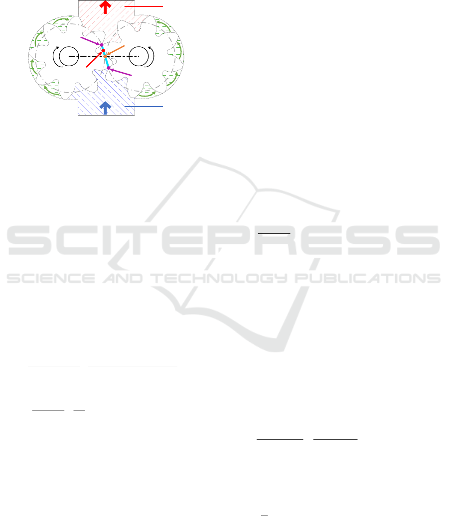
Figure 1: Gear pump meshing schematic.
Figure 1 shows the meshing schematic of the gear
pump. Based on operation principle and flow
continuity assumption, the instantaneous flow rate of
a gear pump is
()()
22 222
2
vpc pac
QB Rhh f B RR f
ωω
=+−=−−
(6)
where R
a
and R
c
are the radius of the addendum and
the pitch circles, respectively, ω
p
is the angular
velocity of the pump, f is the distance between the
meshing point P’ and the pitch point P.
The internal leakage of gear pump is inevitable
especially those which deliver high-pressure fluid.
Leakage flow includes two parts of axial and radial
clearance leakage (Chen, et al., 2018).
The total leakage can be expressed by
()
()
()
()
()
33 2 2
3
bh p b z
bh
s
bz bz
2
Δ
4
12 ln / 80 ln /
sR R
sp
Q
RR RR
θθρω
θθ
μμ
+−
+
=+
(7)
3
δpa
e0
Δ1
=
630
p
QB nR
SZ
δ
πδ
μ
−
(8)
where Q
s
and Q
δ
are the axial and radial clearance
leakage respectively. R
b
is the root radius, R
z
is the
radius of the gear shaft, θ
h
is the wrap angle of the
high-pressure cavity, θ
b
is the half wrap angle within
the transition zone, s is the axial clearance, δ is the
radial clearance, μ is the kinetic viscosity which is
vulnerable to the temperature of the fluid, B is the face
width, S
e
is the crest width, Z
0
is the number of the
teeth in transition zone, n
p
is the rotation speed of the
pump.
Thus, the real flow rate can be written as
vl v sδ
()QQ Q Q Q Q=−=− +
(9)
There is no doubt that the real flow rate is not only
determined by rotation speed but also depends on the
differential pressure and the fuel temperature. These
factors bring system uncertainties and impair pump
accuracy. Moreover, to obtain a complete model of
the PMSM, it is necessary to describe the dynamic
torque of the gear pump. A gear pump with unloading
groove is modelled.
For the driven gear,
2n n b
2o ak b
2o 2n m2
Δ
MFR
M
SpBR
MM
=
=
=
η
(10)
F
n
is the engaging force of two gears, so it can be
expressed as
ak
n
m2
ΔSBp
F =
η
(11)
Similarly, for the driving gear,
1n n b
1o ck b
Δ
MFR
M
SpBR
=
=
(12)
M
1n
, the torque on the driving gear plus the torque
generated by the fuel in the tooth groove balances
with the product of the system input torque M and its
mechanical efficiency η
m1.
m1 1o 1n
M
MM=+
η
(13)
ck b ak b
m1 m1 m2
ΔBR Δ
=
Sp SpBR
M +
ηηη
(14)
The length of an involute tooth profile is (Li, et
al., 2006)
22
ak b α k2
1
(tan tan )
2
SR=−
αα
(15)
O
1
O
2
Starting
Meshing Point
P
1
Pitch Point
P
P
2
Inlet
Outlet
Meshing Point
P’
Ending
Meshing Point
ω
p
ISAIC 2022 - International Symposium on Automation, Information and Computing
768
22
ck b α k1
1
(tan tan )
2
SR=−
αα
(16)
Substituting Eq. (15) and Eq. (16) into Eq. (14)
yields:
22 2 2 2
bak2ak1
m1 m1 m2
Δ tan tan tan tan
=
2
BR p
M
−−
+
αα αα
ηηη
(17)
where α
a
is the pressure angle of the tip circle, α
k1
and
α
k2
are respectively the pressure angle of the driving
and the driven gear at the meshing point, γ
k1
and γ
k2
are the central angle corresponding to the meshing
point.
3 CONTROLLER DESIGN
Involving the PMSM and a gear pump, model un-
certainties and unavoidable disturbances are inherent
issues for an electric fuel pump under all conditions.
The established mathematical pump model can only
describe the input-output relationship, but there still
exist certain operational uncertainties. For example,
increasing sealing clearance due to wear and tear,
cavitation due to high rotation speed or low inlet
pressure, brings about the uncertainty, which cannot
be fully accounted for in the modelling. Besides,
PMSM is a typical multi-variable and strongly-
coupled system, which is often disturbed by various
uncertainties such as the external uncertain loads, the
internal non-constant friction, and the nonlinear
magnetic field effects. Its operation highly affects the
performance of flow control. In addition, considering
that the output of the turbine flowmeter is a frequency
signal, either through the circumferential method or
frequency measurement method of its output
processing is unable to guarantee the accuracy and
dynamic performance of the flow signal. It is difficult
to achieve accurate and rapid feedback of fuel flow.
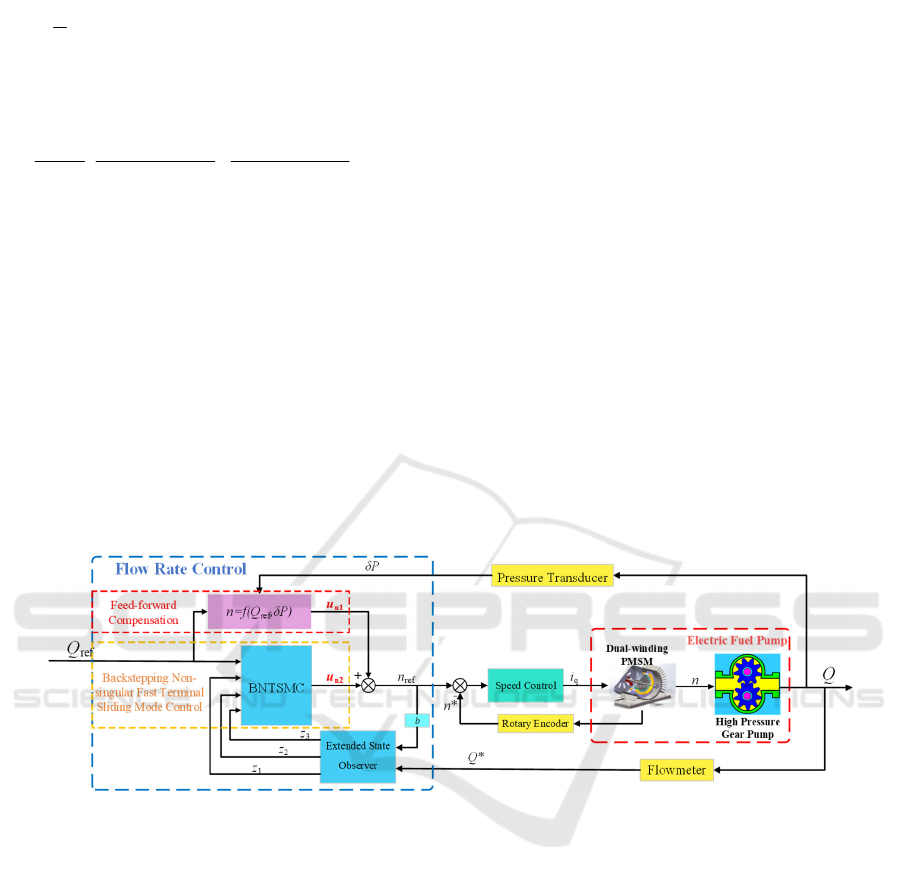
Therefore, a fuel flow hybrid control strategy is
proposed. It consists of a feed-forward compensation
based on differential pressure and backstepping non-
singular fast terminal sliding mode control with
extend state observer.
Figure 2: Schematic diagram with fuel flow hybrid control.
3.1 Feed-Forward Compensation
Based on Differential Pressure
In order to obtain the relationship between flow rate
and rotation speed of the electric fuel pump, a
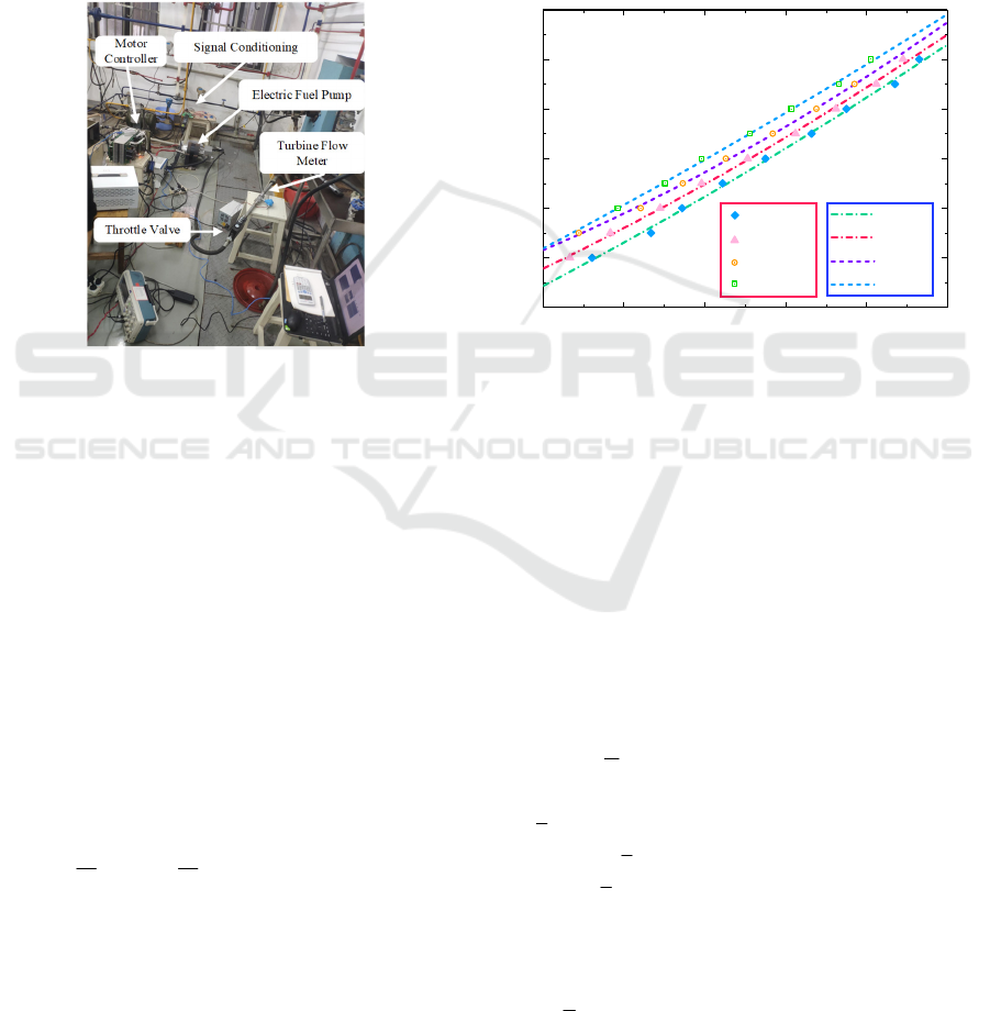
prototype pump is manufactured and tested. Figure
3(a) depicts the experimental system. Two pressure
transducers and a flowmeter were adopted to collect
the required pressure and fuel flow respectively.
Figure 3(b) depicts the comparison between the
tested data and the fitted data. The root mean squared
errors (RMSE) of the fitted curve is less than 0.5 under
varied operating conditions, suggesting that the fitted
curve can well represent the flow-speed-outlet
pressure relationship of a prototype electric fuel pump.
According to the tested data shown in Figure 3(b),
the relationship between rotation speed and flowrate
can be obtained, which is also the input of the flow
controller.
n1 ref
(,)ufQP
δ
=
(18)
3.2 Liner Extended State Observer
According to the input and the output of the
controlled object, a well-designed ESO can estimate
the total disturbance on the system (Han, 2002; Gao,
2003).
A second-order system is used to mathematically
characterize the electric fuel pump as
Hybrid Control Based on Backstepping Sliding Mode Control for Flow Modulation of Electric Fuel Pump
769
() ()
,,
Q
fabbn t
un
yQ
=
=++
=
=
γ
γγ ω
(19)
where ω(t) is the external interference and f(γ,a,b) is
the internal disturbance, the rotation speed n and the
flow rate Q are the input and output of the electric fuel
pump respectively.
The following extended state observer is designed
based on the model of electric fuel pump system:
()
0
0
12 01
2
23 1
3
31
3
3( )
()
n
zz zy
zz zybu
zzy
ω
ω
ω
=− −
=− −+
=− −
(20)
where z
1
and z
2
is, respectively, the observation value
and its differential of the flow rate; z
3
is the estimated
value of the disturbance.
(a) Experimental system (b) Comparison between tested data and fitted results
Figure 3: Experimental system and results.
3.3 Backstepping Non-Singular Fast
Terminal Sliding Mode Control
The basic idea of the backstepping control method is
to decompose the complex nonlinear system into
subsystems that do not exceed the system order, and
then design Lyapunov functions and intermediate
virtual control variables for each subsystem, push the
subsystem back to the whole system, and integrate
them to complete the design of the whole control law.
Lemma 1: If the Lyapunov function V(t,x) is
positive definite, and
12
VkVk≤− +
, k
1
and k
2
are
bounded constants, which
12
,0kk≥
, then
1
22
11
(, ) (0)
kt
kk
Vtx V e
kk
−
≤+ −
(21)
The fuel flow tracking error is defined as
1d
1dd
eQQ
eQQ Q
γ
=−
=− =−
(22)
Take the virtual control as
111d
ce Q=− +
α
(23)
According to the design process of the
backstepping method, α
1
will be derived, but multiple
derivations will increase the number of terms in α
1
.
Therefore, a first-order low-pass filter is employed to
filter the virtual control values, which simplifies the
parameters and structure of the final control method.
Take
1
α
as the output of the low-pass filter of α
1
111d
11 1
11
(0) (0)
ce Q
α
τα α α
αα
=− +
+=
=
(24)
The error of resulting filter is
11
L
αα
=−
(25)
0 1020304050
0
1000
2000
3000
4000
5000
6000
Rotation Speed (r/min)
Flow Rate (L/min)
2 MPa
4 MPa
6 MPa
8 MPa
Fitted
2 MPa
Tested
6 MPa
8 MPa
4 MPa
ISAIC 2022 - International Symposium on Automation, Information and Computing
770

Combining Eq. (24), the derivative of L is as
follows:
11 1
L
L
ααα
τ
=−=−
(26)
As the system state variables and their derivatives
are bounded, define a non-negative continuous
function η such that
1
αη
≤
.
22
1
L
L
LL L L
αη
ττ
=−≤ −
(27)
Define the tracking error variable of the second
subsystem as
21
e
γ
α
=−
(28)
Substituting Eq. (28) into Eq. (22)
12 1 d 112
ee Q cee=+α− =− +
(29)
In the first subsystem, derive the Lyapunov
function:
22
11
11
22
VeL=+
(30)
The derivative of V
1
is as follows:
2
2
111 11 12 1
L
VeeLL ceeeL
α
τ
=+=−++ −
(31)
From the Young's inequality,
2
2
1
2
4
2
LL L
η
ηη
=⋅ ≤+
(32)
Substituting Eq. (32) into Eq. (31) yields
2
2
11112
22
22
11 12
4
L
VceeeL
L
ce ee L
η
τ
η
τ
≤− + + −
≤− + + + −
(33)
If the design of step 2 allows e
2
converges to 0,
then there is
{
11
1
2
1
2min ,1
4
VkVc
kc
c
≤− +
=−−
τ
η
=
(34)
According to Lemma 1 and Eq. (34)
11 1
0 ( ) (0) (0), 0
kt
ccc
Vt V e V t
kkk
−
≤≤+ − ≤+ ∀≥
(35)
The above equation shows that
1
V
and
1
V
are both
bounded, and
1
lim
t
c
V
k
→∞
=
.
When e
2
converges to zero, the system state meet
half global bounded consistency conditions, 1 stable
subsystems, and the system tracking error
convergence, e→0, Q→Q
d
The following fast terminal sliding-mode is
selected.
1
sx x x
λε
αβ
=+ +
(36)
where λ=k/h, ε=p/q, k, h, p, q are all positive odd,
and 1<ε<2, λ>ε, α and β are positive constants.
Drawing on the idea of integral sliding mode, let
2
0
t
x
ed
τ
=
,then Eq. (36) will be
12 2 2
00
()
tt
s
ed ed e
λε
τα τ
β
=+ +
(37)
The derivative of s
1
is
2
2
11
12 2 2 2
0
11
222 21
0
()
() ((,,) )
t
t
n
se ed e ee
eedeefabbu
λε
λε
λα τ εβ
λα τ ε
βγ
ωα
−−
−−
=+ +
=+ + + +−
(38)
Define approaching law as
/
111
()
mn
s
ss
κ
ξ
σ
=− +
(39)
where
2
1
e
−
=
ε
κβε
,m and n are positive odd
0<m/n<1,
ξ
>0,
σ
>0.
Let Eq. (38) equals Eq. (39) gives the control law
as follows:
212
222
0
2
/
1
1
(())
1
(,,) ()
t
n
mn
eede
u
b
ssfabt
ελε
λα τ
λβ
ξ
σ
γ
ωα
−−−
+
=−
+++ +−
(40)
Hybrid Control Based on Backstepping Sliding Mode Control for Flow Modulation of Electric Fuel Pump
771
The ESO is used for real-time observation of the
total internal and external disturbances of the system,
z
3
= f(γ,a,b)+ ω(t), with dynamic compensation in the
control law section.
201
212/
0222
0
131
11
(())
n
t
mn
uuu
ueedess
b
uz
ελε
λα τ
ξ
σ
λβ
α
−−−
=+
=− + + +
=−
(41)
Define the Lyapunov function for the second
subsystem
/
/1 2
211
111
1
21 1
()
()
mn
mn
Vss
sss
es s
ε
κξ σ
βε ξ σ
+
−
=
=− +
=− +
(42)
When s
2
≠0, ε= p/q, 0 < m/n < 1, 1 < p/q < 2.
Since p, q, m, and n are positive odd numbers, e
1
> 0,
s
m/n
+1 > 0, then V
1
≤ 0. From Lyapunov's theorem,
we can get that the system will be stable and the state
error e
2
→0 in a certain time. When e
2
converges to 0,
Eq. (34) holds, and the whole closed-loop system is
bounded and stable in all states.
4 RESULTS AND DISCUSSIONS
To verify the validity of the proposed fuel flow
control strategy, simulations are conducted based on
the fuel supply demand of a small-thrust turbofan
engine.
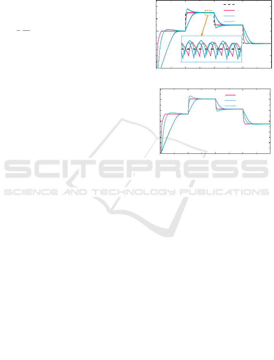
The fuel flow and rotation speed response of the
pump are shown in Figure 4. With the delivery
pressure of 6 MPa, Figure 4(a) depicts several typical
responses to the flow rate command. The flow
command steps from 30 L/min to 45 L/min at 0.2 s
and then step back to 35 L/min at 0.4 s is given. For
each control method, the fuel flow can be controlled
at its required value. However, the system with hybrid
control lasts for less than 0.1 s to reach the steady state,
and the settling time is only 53% of the system using
ADRC, with a smaller overshoot compared to SMC.
Figure 4(a) illustrates the flow fluctuation for the
command of 45 L/min. The flow rate undulates from
44.8 L/min to 45.2 L/min, at a frequency of about 450
Hz, which is consistent with the theoretical value of
the gear pump. The pump system with the proposed
control strategy exhibits a fast increase in speed,
creating the condition for the pump to reach the
desired flow rate faster.
(a) Flow rate
(b) Rotation speed
Figure 4: Pump responses under a step command.
Delivery pressure of the electric fuel pump is
easily affected by airborne fuel pipeline or a
combustor of the engine. It is a leading factor that
adds an obstacle on the flow control. Thus, an
important performance of the electric fuel pump is the
ability to suppress disturbances, such as the delivery
pressure. In order to find a comprehensive superior
method, some simulations are conducted to verify
their robustness and anti-interference performance.
Under any conditions, the fuel supply must be
adequate for the engine. For that reason, the constant
flow command of 30 L/min, as well as the varying the
delivery pressure at the outlet of the pump, is
simulated. As shown in Figure 5, the output pressure
step from 6 MPa to 7 MPa is given, following an
opposite step to the initial. The flow rate plunges
instantly when the delivery pressure lifts. Since the
command remains constant, the controller needs to
compensate for the flow loss due to leakage by
increasing the speed output. An ever-rising
differential pressure is responsible for the increasing
0.0 0.2 0.4 0.6 0.8
10
20
30
40
50
Flow Rate (L/min)
Time (s)
Command
Compound Control
ADRC
SMC
0.352 0.356
44.6
44.8
45.0
45.2
45.4
0.0 0.2 0.4 0.6 0.8
1000
2000
3000
4000
5000
6000
Rotation Speed (r/min)
Time (s)
Compound Control
ADRC
SMC
ISAIC 2022 - International Symposium on Automation, Information and Computing
772
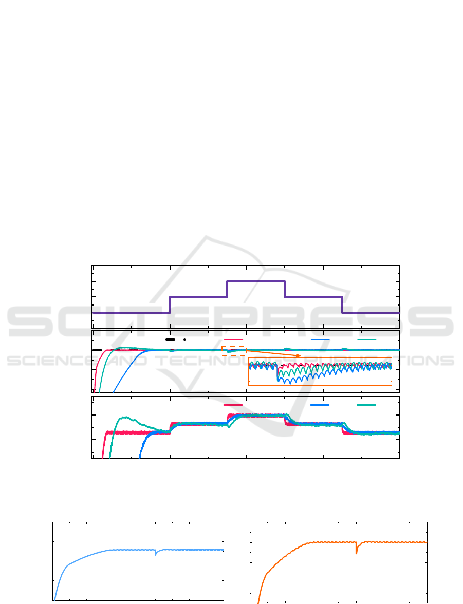
leakage. Likewise, the flow rate reduces in response
to a drop in the pressure by adjusting the output of the
speed controller, so that the flow rate can keep very
close to the command. The system with hybrid
control exhibits faster response and smaller error rate,
so better robustness and stronger interference
resistance is verified.
As shown in Figure 6(a) and Figure 6(b), an open
circuit fault occurred in the UVW phase winding at
the moment of 0.06 s. The motor speed decreased
instantaneously by about 280 r/min, and then
stabilized within 2 ms. The flow rate is reduced by
about 3 L/min due to the sudden drop in rotation
speed, and then stabilizes with the speed. Figure 28
shows that the speed control stability is good,
fluctuating about 8%, and the fault state adjustment
time is less than 2 ms, which effectively realizes the
fault tolerance function of the system. Figure 6(c) to
Figure 6(f) shows the response of the motor. Before
an open-circuit fault occurs, each set of windings
takes 50% of the power each with a peak current of
16 A. When an open-circuit fault occurs in the U-
phase winding, the current in each phase of the UVW
set of windings is zero, while the current in each
phase of the ABC set of the other normal winding is
doubled with a peak current of 32 A each. The ABC
windings takes 100% of the power to ensure that the
system output power remains unchanged. Figure 6(c)
shows the torque waveform generated by the normal
set of motor winding ABC, and Figure 6(d) shows the
total electromagnetic torque waveform of the motor.
The figure shows that the output torque of the normal
phase winding ABC is half of the rated load before
the fault. When the fault occurs, as the fault phase
winding UVW no longer provides output power, the
ABC winding will output the entire rated load power
and the output torque doubles to 10 N·m. The total
electromagnetic torque of the motor is stable around
10 N·m before and after the open-circuit fault of the
U-phase winding. The torque is basically unchanged
before and after the open-circuit fault.
Figure 5: Flow rate under disturbance.
(a) Rotation speed (b) Flow rate
6.0
6.5
7.0
7.5
10
20
30
40
0.0 0.2 0.4 0.6 0.8
3600
3800
Pressure (MPa)
Flow Rate (L/min)
Command Compound Control ADRC SMC
0.34 0.35 0.36 0.37 0.38 0.39
29.0
29.5
30.0
30.5
Rotation Speed (r/min)
Time (s)
Compound Control ADRC SMC
0.02 0.04 0.06 0.08 0.10
1000
2000
3000
4000
5000
Rotation Speed (r/min)
Time (s)
0.02 0.04 0.06 0.08 0.10
15
20
25
30
35
Flow Rate (L/min)
Time (s)
Hybrid Control Based on Backstepping Sliding Mode Control for Flow Modulation of Electric Fuel Pump
773
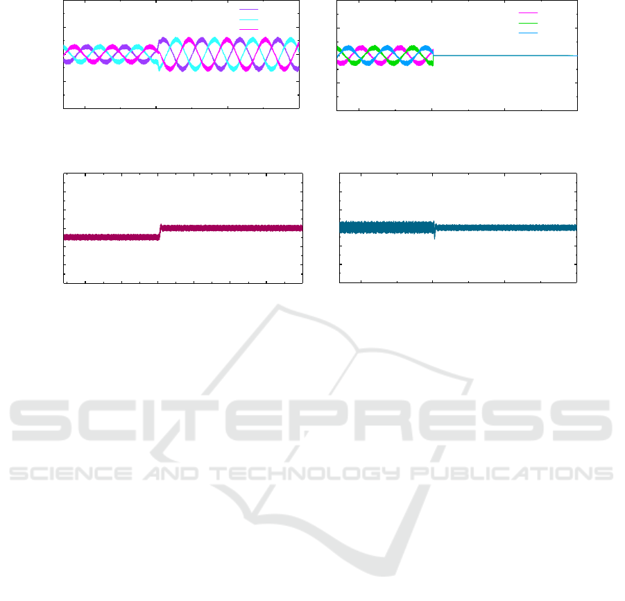
(c) Current of phase ABC (d) Current of phase UVW
(e) Torque of phase ABC (f) Total output torque
Figure 6: Response with Open Circuit Fault.
5 CONCLUSIONS
To achieve accurate flow control of an electric fuel
pump, this paper has proposed a hybrid control
strategy. A PMSM and a gear pump are
mathematically modelled, and simulations with the
proposed control strategy have been carried out under
typical conditions. The results are analysed and
compared with the results of using ADRC and SMC.
The main conclusions are drawn as the following:
(1) With the consideration of instantaneous flow
rate, internal leakage and dynamic torque, a complete
mathematical model of an electric fuel pump has been
developed.
(2) The proposed hybrid control strategy consists
of a feed-forward compensation based on differential
pressure and backstepping non-singular fast terminal
sliding mode control with extend state observer. It can
reduce the flow response time and bring about a
negligible error of steady-state error, compared with
the system using ADRC and SMC. When there exists
pressure fluctuation at the pump outlet, the proposed
control method exhibits better anti-interference
ability including less than 0.5% of steady-state error
of the system output.
(3) Considering the possible fault of the motor
during the operation of the electric fuel pump, the
simulation of the motor open circuit fault was carried
out. Results show that the fault state adjustment time
is less than 2 ms, and the total torque is basically
unchanged before and after the open-circuit fault
occurs.
ACKNOWLEDGEMENTS
The work reported in this article is financially
supported by the Postgraduate Research & Practice
Innovation Program of NUAA, xcxjh20220207.
Meanwhile, all the staff and fellow researchers
providing technical and academic support are also
greatly appreciated.
REFERENCES
Ding R, Xiao L, Jin X. Robust Control for Electric Fuel
Pump with Variant Nonlinear Loads Based on a New
Combined Sliding Mode Surface[J]. International
Journal of Control Automation and Systems, 2019,
17(3):716-728.
Jiang X, Huang W, Cao R, et al. Electric Drive System of
Dual-Winding Fault-Tolerant Permanent-Magnet
Motor for Aerospace Applications[J]. IEEE
-100
-50
0
50
100
Current (A)
Time (s)
Phase A
Phase B
Phase C
0.04 0.06 0.08 0.10
-100
-50
0
50
100
Current (A)
Time (s)
Phase U
Phase V
Phase W
0.04 0.06 0.08 0.10
-20
-10
0
10
20
30
40
Torque (N·m)
Time (s)
0.04 0.05 0.06 0.07 0.08 0.09 0.10
-20
-10
0
10
20
30
40
Torque (N·m)
Time (s)
0.04 0.06 0.08 0.10
ISAIC 2022 - International Symposium on Automation, Information and Computing
774

Transactions on Industrial Electronics, 2015,
62(12):7322-7330.
J.Q. Han, From PID Technique to Active Disturbances
Rejection Control Technique, Basic Auto-motion,
(2002).
K. Chen, L.F. Qian, Y.U. Xiao-Peng, H.M. Zheng, X. Fang,
Research on random internal leakage model for
external gear pumps, Chinese Journal of
Computational Mechanics, (2018). (In Chinese)
Liu, Zhongqiang, et al. "Application of Improved BP
Neural Network to the Modeling of Electric Gear
Pump." International conference on Big Data
Analytics for Cyber-Physical-Systems. Springer,
Singapore, 2020.
McLoughlin Adam, Rolls-Royce plc, “Engine Powerplant
Electrical Systems”, More Electric Aircraft Forum,
2009.
Mohammadi S J, Miran Fashandi S A, Jafari S, et al. A
scientometric analysis and critical review of gas
turbine aero-engines control: From Whittle engine to
more-electric propulsion[J]. Measurement and Control,
2021, 54(5-6): 935-966.
Morioka N, Oyori H, Gonda Y, et al. Development of the
Electric Fuel System for the More Electric
Engine[C]//ASME Turbo Expo: Turbine Technical
Conference & Exposition. American Society of
Mechanical Engineers, 2014.
M. Rundo, Models for Flow Rate Simulation in Gear
Pumps: A Review[J]. Energies, 2017, 10(9): 1261.
Newman, R., “The More Electric Engine Concept,” SAE
Technical Paper 2004-01-3128, 2004.
N. Morioka, H. Oyori, More Electric Architecture for
Engine and Aircraft Fuel System, Sae Technical
Papers, 8 (2013).
X. Wang, J. Atkin, C. Hill, S. Bozhko, Power Allocation
and Generator Sizing Optimisation of More-Electric
Aircraft On-board Electrical Power during Different
Flight Stages, AIAA Propulsion and Energy 2019
Forum, 2019.
Y. Li, Liu, Dynamic Reappearance on Torque Calculation
in a Gear Pump with External Mesh, Transactions of
the Chinese Society for Agricultural Machinery,
(2006). (In Chinese).
Z. Gao, Scaling and bandwidth-parameterization based
controller tuning, IEEE, 2003.
Hybrid Control Based on Backstepping Sliding Mode Control for Flow Modulation of Electric Fuel Pump
775
