
Practical Validation of ORB2 SLAM Mapping on Indoor Logistic
UAV Application
Wahyu A. Candra
1
a
, Rochdi Merzouki
2
b
and Mohamed Djemai
3
c
1
Manufacture Automation and Mechatronics Engineering Dept., Polman Bandung, Jl. Kanayakan 21, Bandung, Indonesia
2
CRIStAL, Professor at Ecole Polytechnique de Lille, Universite de Lille, Lille, France
3
LAMIH, Professor at Universite Polytechnique des Hauts de France, Valenciennes, France
Keywords: Slam, ORB, ROS, Indoor Logistic, Drone, UAV.
Abstract: Aiming at complex unstructured environment of manufacture production line and highly requirement to raise
the production volume, in order to meet the requirement, this study proposes an UAV (Unmanned Aerial
Vehicle) as one of tools or methods to solve this problem. The UAV drone (Parrot Bebop 2) will perform on
part delivery from one point to another inside the manufacture plan using spatial area. To support this AIP
mini manufacture plant is provided by utilize two different rooms as production line and inspection plant.
This study deals with the proposed ORB-SLAM 2 method to generate initial map between inspection room
and production line of AIP plant at 3
rd
floor Polytechnic of Lille. The study showed results while ORB Slam
combined to bebop drone which less memory size, data delay and monocular type camera performs mapping
both in the simulation world by ROS Gazebo and real environment world.
1 INTRODUCTION
Manufacture plants divided into two type of
environment, there are structured or unstructured.
The differences between both are while unstructured
one requires autonomous level. Otherwise, structured
environment is best for automated agents. Most of
conventional manufacture plants are unstructured
therefore more challenging method are required to
implement the autonomous application here (Kolski,
Ferguson, Bellino, & Siegwart, 2006) (Melingui,
Chettibi, Merzouki, & Mbede, 2013).
To provide the autonomous application in the
unstructured environment then SLAM method is
required. A large number of SLAM techniques have
been proposed on many applications. Whether
outdoor or indoor application SLAM, these
techniques have attracted more and more attention for
any environments and many robot types (Taketomi,
Uchiyama, & Ikeda, 2017).
ORB Slam 2 is considered as one method to be
implemented in this case since the method shows
potential result. (Mur-Artal & Tardós, 2017) Since
a
https://orcid.org/0000-0003-0888-6363
b
https://orcid.org/0000-0001-9153-6078
c
https://orcid.org/0000-0002-5375-9470
Bebop 2 drone is used, the mapping could be done
using monocular camera and suitable for GPS denial
environment. Currently, many ORB slam application
used for outdoor activity which GPS use could be
help the performance of the Slam its self (Lakhal,
Koubeissi, Aitouche, Sueur, & Merzouki, 2021).
The study organized in the AIP area at floor 3
rd
of
Polytechnique de Lille by using their 2 separate
rooms. The AIP area represented as unstructured
plants. One on TP Robotique Industrielle room C-303
as production line and TP Logique Industrielle room
C-304 as inspection room. In the scenario of
delivering small part Bebop drone was sent from
inspection room to production line and vice versa.
The remaining of this paper organized as follows.
In section 2, the SLAM concepts are briefly reviewed
and model of visual SLAM is formulated. In section
3, the system requirement and specification are
discussed. In section 4, the ORB SLAM mapping
process and the experimental validation using
simulation and real world are illustrated. Finally,
conclusions are given in section 5.
976
Candra, W., Merzouki, R. and Djemai, M.
Practical Validation of ORB2 SLAM Mapping on Indoor Logistic UAV Application.
DOI: 10.5220/0011973800003575
In Proceedings of the 5th International Conference on Applied Science and Technology on Engineering Science (iCAST-ES 2022), pages 976-981
ISBN: 978-989-758-619-4; ISSN: 2975-8246
Copyright © 2023 by SCITEPRESS – Science and Technology Publications, Lda. Under CC license (CC BY-NC-ND 4.0)
2 WORKING PRINCIPLES
In this section the basic principle of visual SLAM is
discussed.
2.1 Visual SLAM
The history of the research on SLAM has been over
30 years, and the models for solving SLAM problems
can be divided into two categories: filtering based
methods and graph optimization based methods
(Scaramuzza & Fraundorfer, 2011). The map
building problem for an unknown environment with
use of on-board sensors while solving the localization
problem at the same time is known as Simultaneous
Localization and Mapping.
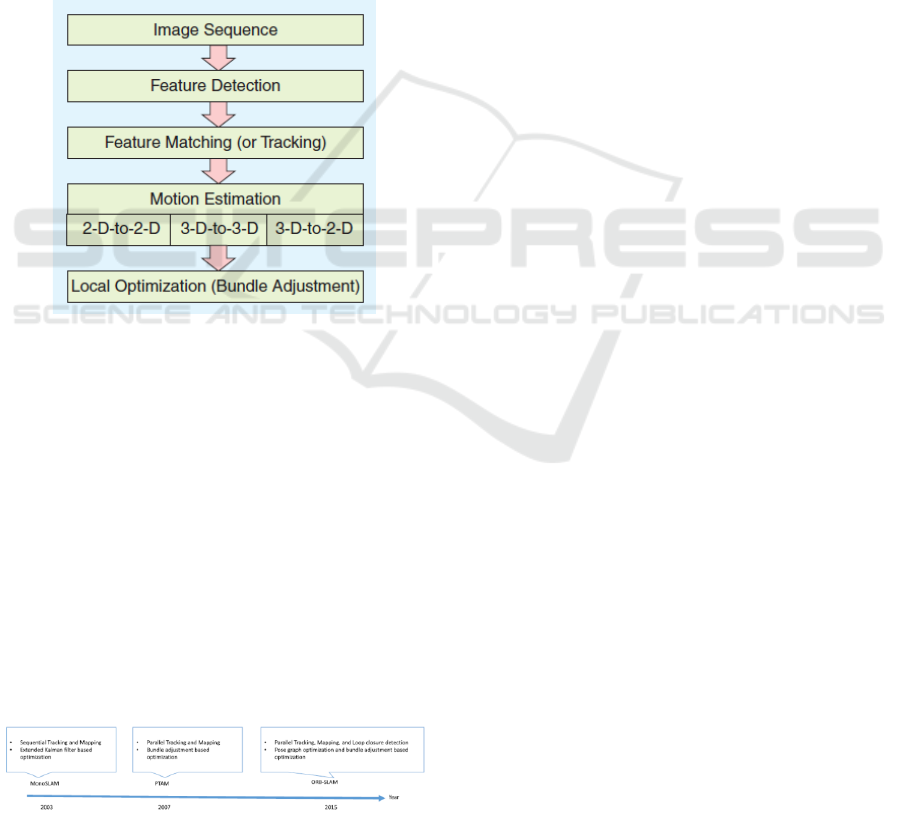
Figure 1: Main Components of Visual Odometry System.
This SLAM was originally proposed to achieve
autonomous control of robots in robotics. Then,
SLAM-based applications have widely become
broadened such as computer vision-based online 3D
modelling, augmented reality (AR)-based
visualization, and self-driving cars, autonomous
underwater vehicles, planetary rovers, newer
domestic robots and even inside the human body.
SLAM methods can be classified at least by used
sensors and output map type and sometimes they have
common underlying math methods (e.g. Kalman filter
or bundle adjustment). SLAM algorithms are tailored
to the available resources, hence not aimed at
perfection, but at operational 9 compliance.
(Taketomi, Uchiyama, & Ikeda, 2017)
Figure 2: Featured-based Method SLAM.
In navigation, robotic mapping and odometry for
virtual reality or real environment, simultaneous
localization and mapping (SLAM) is the
computational problem of constructing or updating a
map of an unknown environment while
simultaneously keeping track of a robot’s location
within it. Popular approximate solution methods
include the particle filter, Extended Kalman filter,
Covariance intersection, and GraphSLAM. In a few
words all these methods are based on Bayesian
inference provide a technique for random value
estimation. (Huletski, Kartashov, & Krinkin, 2015)
2.2 Elements of Visual SLAM
Basic Modules. The basic modules are composed
into framework, which consist of Initialization,
tracking and mapping.
Initialization is required to define a certain
coordinate system for camera pose estimation and 3D
reconstruction in an unknown environment. Then
tracking and mapping are performed to continuously
estimate camera poses. In the tracking, the
reconstructed map is tracked in the image to estimate
the camera pose of the image with respect to the map.
In the mapping, the map is expanded by
computing the 3D structure of an environment when
the camera observes unknown regions where the
mapping is not performed before.
Additional Modules. The following two
additional modules are for stable and accurate
performance. It also included in visual SLAM
algorithms according to the purposes of applications.
It consists of Relocation and Global map
optimization. The re-localization is required when the
tracking is failed due to fast camera motion or some
disturbances and the global map optimization is
normally performed in order to suppress the
accumulative estimation error according to the
distance of camera movement.
3 REQUIREMENT AND
SPECIFICATION
To perform ORB-Slam mapping by Bebop UAV
drone, ROS system is implemented by using both
ROS Gazebo Simulator and Real robot in real world
application.
3.1 ROS System
For working with Parrot Bebop 2 in the ROS
environment, firstly Ubuntu OS must be installed in
our workstation. It is because ROS is built from
Practical Validation of ORB2 SLAM Mapping on Indoor Logistic UAV Application
977

3ebian based packages. The Parrot Bebop 2 required
Ubuntu 14.04 LTS version as minimum or Ubuntu
18.04 LTS version as the latest one, however Ubuntu
16.04 LTS version is the common used version. UAV
drone that equipped with software driver which able
to run as well in the ROS platform.
ROS Navigation is fairly simple on a conceptual
level. It takes in information from odometry and
sensor streams and outputs velocity commands to
send to a robot. Use of the Navigation on an arbitrary
robot, however, is a bit more complicated. As a pre-
requisite for navigation stack use, the robot must be
running ROS, have a tf transform tree in place, and
publish sensor data using the correct ROS Message
types. Also, the Navigation Stack needs to be
configured for the shape and dynamics of a robot to
perform at a high level. (Pyo, Cho, Jung, & Lim,
2015)
Figure 3: ROS Navigation Stack.
ROS has a package that performs SLAM, named
Navigation Stack, however, some details of its
application are hidden, and considering that the
programmer has some expertise. ROS has a set of
resources that are useful so a robot is able to navigate
through a medium, in other words, the robot is
capable of planning and following a path while it
deviates from obstacles that appear on its path
throughout the course. These resources are found on
the navigation stack (Fabro, Guimarães, de Oliveira,
Becker, & Brenner, 2016).
3.2 ORB SLAM 2 System
ORB-SLAM is the visual SLAM method that utilizes
ORB-features and doesn’t use any external odometry.
The ORB algorithm has several features. During
robot exploration the place recognition database is
constructed. This database contains bag of words
representation of the current camera image that is
bound to the specific position in the map. This
database allows to perform queries with the set of
currently observed ORB descriptors to recognize
current place. Details on the usage of such database
are described in. Another feature of this SLAM is the
visibility graph in which vertices are key frames and
an edge connects two vertices if they share enough
common features. Such graph is useful for finding
several frames with the images of the same object
from different view angles (Mur-Artal & Tardós,
2017).
ORB Descriptor
ORB (Oriented FAST and Rotated BRIEF) are
binary features invariant to rotation and scale (in a
certain range), resulting in a very fast recognizer with
good invariance to viewpoint. ORB was conceived
mainly because SIFT and SURF are patented
algorithms. (Calonder, Lepetit, Strecha, & Fua, 2010)
Oriented-FAST, however, FAST features do not
have an orientation component and multiscale
features. So orb algorithm uses a multiscale image
pyramid. An image pyramid is a multiscale
representation of a single image that consist of
sequences of images all of which are versions of the
image at different resolutions. Each level in the
pyramid contains the down sampled version of the
image than the previous level. Once ORB has created
a pyramid it uses the fast algorithm to detect key
points in the image. By detecting key points at each
level ORB is effectively locating key points at a
different scale. In this way, ORB is partial scale
invariant.
Steered BRIEF, allow BRIEF to be invariant to
in-plane rotation. Matching performance of BRIEF
falls off sharply for in-plane rotation of more than a
few degrees. A more efficient method is to steer
BRIEF according to the orientation of key points.
rBRIEF is steered BRIEF by applying greedy
search algorithm for set of uncorrelated tests on it.
Therefore the result of rBRIEF has significant
improvement in the variance and correlation over
steered BRIEF.
Bundle Adjustment
ORB-SLAM 2 performs BA to optimize the
camera pose in the tracking thread (motion-only BA),
to optimize a local window of key frames and points
in the local mapping thread (local BA), and after a
loop closure to optimize all key frames and points
(full BA). ORB-SLAM 2 use the Levenberg–
Marquardt method implemented in g2o (“general
graph optimization”).
Motion-only BA optimizes the camera orientation
and position. Motion-only BA optimizes the camera
orientation and all points seen in those key frames.
Full BA is the specific case of local BA, where all key
frames and points in the map are optimized, except
the origin key frame that is fixed to eliminate the
gauge freedom.
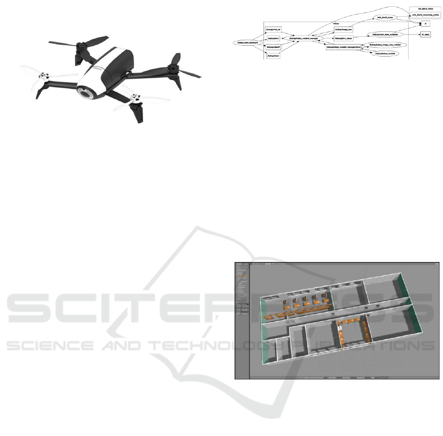
3.3 UAV System
Parrot, a France-based company, has been on a hit or
miss run with the drones they released in the past
years. The AR.Drone 2.0 and other previous models
iCAST-ES 2022 - International Conference on Applied Science and Technology on Engineering Science
978
have had bugs and glitches the company had to iron
out after their release.
Figure 4: Parrot Bebop 2.
Bebop has on-board sensors for autonomous
flight through the use of GPS for guidance. The
Bebop also has a forward-looking camera for aerial
photography or as sensor input in the Visual SLAM.
The Wi-Fi communications module of Bebop allows
manual control and control by a ROS package called
“bebop autonomy”.
Bebop 2 has hardware specification as followed;
Dual core processor with quad-core GP, 8GB flash
storage system, Built-in GPS: GPS + GLONAS,
performance of 1280kW motor. It has also 14
megapixels wide-angle CMOS camera with 3 photo
formats: RAW, JPEG, DN and Full HD 1080p video
with unique digital image stabilization. It is
embedded with ultrasound sensor, altimeter sensor,
IMU sensor and optical flow camera. Bebop equipped
with 802.11a/b/n/ac Wi-Fi, Wi-Fi MIMO with
2.4GHz antennas.
4 IMPLEMENTATION AND
RESULTS
4.1 ROS Setup
Git is a tool for installation, programming and
developing version of program. Prior to start
programming use some related source of package
links that will be used on this topic as stated in the
previous section.
Parrot-Sphinx aims to run Parrot Bebop 2 both in
the Gazebo simulation environment by firmware the
driver of drone on PC and as well run real robot at the
same time.
To perform both simulation and real environment,
the main core running in ROS platform is by monitor
and diagnose the nodes and topics using rqt_graph as
sown.
Figure 5: Node and Topics Graph.
To have proper result both in simulation and real
world, TF transformation must be set up where origin
of of TF before mapping is odom and after mapping
process is map.
4.2 Simulation Environment
Simulation World. Prior to work in simulation, the
environment, it is called world in the gazebo
simulator, must be prepared. It can be constructed
from either model of Gazebo or own built in model.
In our work, the world is built based on the building
layout of TP Robotique Industrielle room C-303 and
TP Logique Industrielle room C-304 of Polytech Lille
as drawn at Figure .
Figure 6: Production Room World Simulation in Gazebo.
Room C303 has 6x9 m
2
in area which consist of
5 arm-robot with production plant installed. Room C-
304 has an area 6x6 m
2
which consist of inspection
plant table and surrounded by laboratory benches.
The mapping path which departed from inspection
table to production room then went back to inspection
room took about 100 m with coverage area about 115
m
2
and surrounded wall area about 261 m
2
.
Simulation Mapping. For the simulation, the
mapping process, using Parrot Bebop 2 and ORB-
SLAM, took about 1 hour for the 115 m
2
of coverage
area.
Practical Validation of ORB2 SLAM Mapping on Indoor Logistic UAV Application
979
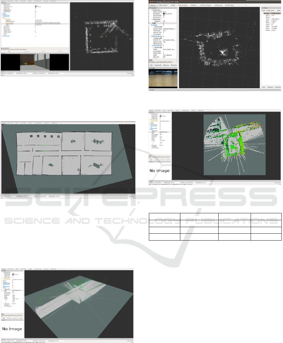
Figure 7: World Simulation for ORB-SLAM Mapping
Progress in RVIZ.
And result of simulation mapping showed as
below,
Figure 8: 2D Mapping Result in RVIZ.
4.3 Real Environment
In the real robot and environment, we don’t create
simulation world. The mapping actions were taken
directly use Parrot bebop drone in real environment
as seen at Figure .
Figure 9: Real Environment 3D Map.
Figure 10: Real robot 3D mapping progress in RVIZ.
Figure 11: Real Environment 3D Point Cloud Mapping.
Table 1: Real robot and environment mapping process.
Attempt
Duration
Bag file
File
1
st
58 min.
232 GB
corrupted
2
nd
32 min.
128 GB
corrupted
3
rd
40 min.
160 GB
good
For real robot and environment, the best mapping
process took about 40 minutes and resulted 160GB of
recorded bag file. However, the map file its self only
consumed 1% of the bag file.
5 CONCLUSIONS
The result showed better in Simulation than in real
world environment. It is due to real world has more
un-controllable variable such as, variety of light along
with drone’s path and dynamically human obstacle.
The result showed less efficient while ORB Slam
method combined into Bebop 2 drone. The lacked
results due to less memory, data transmission delay
and monocular type specification of used Bebop 2
drone.
For further research, required other SLAM
method which probably uses less data or use other
UAV which has better data transmission and
iCAST-ES 2022 - International Conference on Applied Science and Technology on Engineering Science
980

improved camera specification such as stereo camera
or RGB-D camera.
ACKNOWLEDGEMENTS
This work has been supported by AIP and
Polytechnique de Lille and CRIStAL Universite de
Lille, CNRS, The Ministry of Higher Education and
Research and The National Center for Scientific
Research under the LAI Project.
REFERENCES
Calonder, M., Lepetit, V., Strecha, C., & Fua, P. (2010).
Brief: Binary robust independent elementary features.
European conference on computer vision, 778-792.
Fabro, J., Guimarães, R., de Oliveira, A. S., Becker, T., &
Brenner, V. A. (2016). ROS Navigation: Concepts and
Tutorial. Swiss: Springer International Publishing
Switzerland.
Huletski, A., Kartashov, D., & Krinkin, K. (2015).
Evaluation of the Modern Visual SLAM. Artificial
Intelligence and Natural Language and Information
Extraction, (pp. 19-25). St. Petersburg, Russia: IEEE.
Kolski, S., Ferguson, D., Bellino, M., & Siegwart, R.
(2006). Autonomous driving in structured and
unstructured environments. IEEE Intelligent Vehicles
Symposium (pp. 558-563). IEEE.
Lakhal, O., Koubeissi, A., Aitouche, A., Sueur, C., &
Merzouki, R. (2021). Autonomous navigation through
a system of systems cooperation. 2021 16th
International Conference of System of Systems
Engineering (SoSE) (pp. 49-54). Västerås: IEEE.
Melingui, A., Chettibi, T., Merzouki, R., & Mbede, J. B.
(2013). Adaptive navigation of an omni-drive
autonomous mobile robot in unstructured dynamic
environments. 2013 IEEE International Conference on
Robotics and Biomimetics (ROBIO) (pp. 1924-1929).
Shenzen: IEEE.
Mur-Artal, R., & Tardós, J. D. (2017). Orb-slam2: An open-
source slam system for monocular, stereo, and rgb-d
cameras. IEEE transactions on robotics, 33(5), 1255-
1262.
Pyo, Y., Cho, H., Jung, L., & Lim, D. (2015). ROS Robot
Programming. Seul: Robotis Co.
Scaramuzza, D., & Fraundorfer, F. (2011). Visual odometry
[tutorial]. IEEE robotics & automation magazine, 80-
92.
Taketomi, T., Uchiyama, H., & Ikeda, S. (2017). Visual
slam algorithms: A survey from. IPSJ Transactions on
Computer Vision and Applications, 1-11.
Practical Validation of ORB2 SLAM Mapping on Indoor Logistic UAV Application
981
