The Implementation of Eco-Design Through Group Tool Design for
Reinf-FR Towing Pipe Products
Hanif Azis Budiarto
a
, Yuliar Yasin Erlangga, Sidik Permana and Gheiska Amelia Wardhana
Department of Design Engineering, Bandung Polytechnic for Manufacturing, Bandung 40135, West Java, Indonesia
Keywords: Green Manufacturing, Eco-Design, Group Tool, Press Tool, Reinf-FR Towing Pipe.
Abstract: Green manufacturing is a process or system that does not have a negative impact on the environment.
However, in Indonesia, four-wheeled vehicles are still the most popular mode of transportation. With high
demand, car production and the number of components are also increasing. Improving the efficiency of the
tools and machines is necessary for the stamping process. One vehicle component with several process
stages during stamping processes is the Reinf-FR Towing Pipe. Four stages of the process are required to
manufacture the Reinf-FR Towing Pipe components. Eco-design can help to reduce or eliminate the
negative effects of manufacturing on the environment. To implement green manufacturing, a group tool has
been designed using VDI 2222 methods and ISO 14006:2011. By grouping multiple processes into one tool,
only one machine is required.
a
https://orcid.org/0000-0002-1983-3032
1 INTRODUCTION
Four-wheeled vehicles are still the most popular
mode of transportation in Indonesia. This can be
seen in Indonesia, which became Southeast Asia's
country with the highest car sales throughout 2021.
Sales reached 887,202 units, an increase of 66.8%
compared to 2020 (Kurniawan, 2022). In addition,
the issue of the Abolition of Luxury Goods Sales
Tax (PPnBM) is also one of the triggers for people
to buy new cars (Doni, 2021). With high demand,
car production is also increasing. Total car
production in Indonesia during 2021 was 1,121,967
units, an increase of 62.6% from the previous year
(Kurniawan, 2022).
Each car unit consists of many constituent
components. The number of components in the
vehicle causes the need for many tools to produce a
car. Several stages of the process need to be done to
make one vehicle component so that the number of
tools required to make one component can be more
than one. The more tools used, the more machines
required. One vehicle component with several
process stages during manufacture is the Reinf-FR
Towing Pipe.
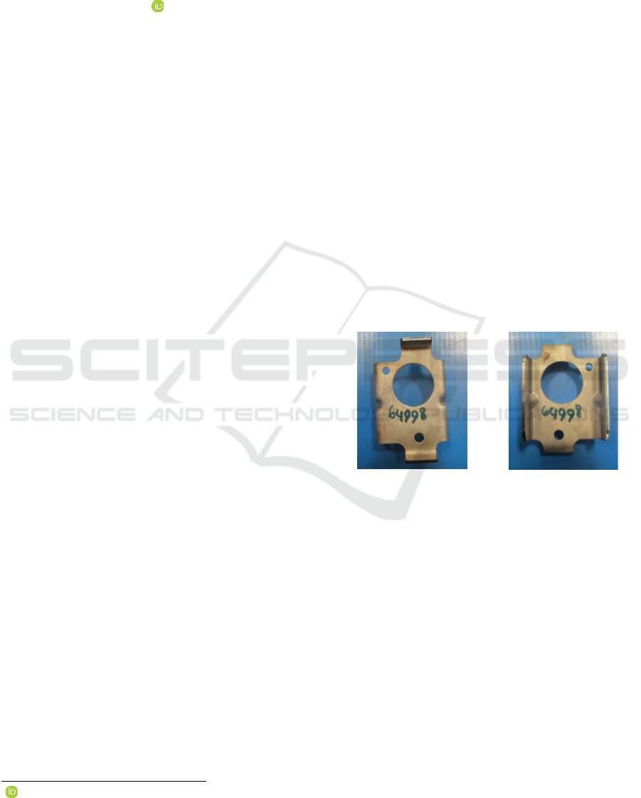
Figure 1: Reinf-FR Towing Pipe Component.
Figure 1 shows the Reinf-FR Towing Pipe
component. This component is one part of the
bumper beam. The bumper beam itself has a
function as a protector of vehicle components such
as engine parts and oil tanks in the event of a major
collision due to accident. Four stages of the process
are required to manufacture the Reinf-FR Towing
Pipe components.
Figure 2 shows the stages of the manufacturing
process for the Reinf-FR Towing Pipe component.
The four stages of the process carried out in the
manufacture of Reinf-FR Towing Pipe components
are blanking & piercing, bending, bending &
embossing, and piercing. The four processes are
carried out using four different single tools, so four
machines will be used for each tool.
942
Budiarto, H., Erlangga, Y., Permana, S. and Wardhana, G.
The Implementation of Eco-Design Through Group Tool Design for Reinf-FR Towing Pipe Products.
DOI: 10.5220/0011966400003575
In Proceedings of the 5th International Conference on Applied Science and Technology on Engineering Science (iCAST-ES 2022), pages 942-946
ISBN: 978-989-758-619-4; ISSN: 2975-8246
Copyright © 2023 by SCITEPRESS – Science and Technology Publications, Lda. Under CC license (CC BY-NC-ND 4.0)
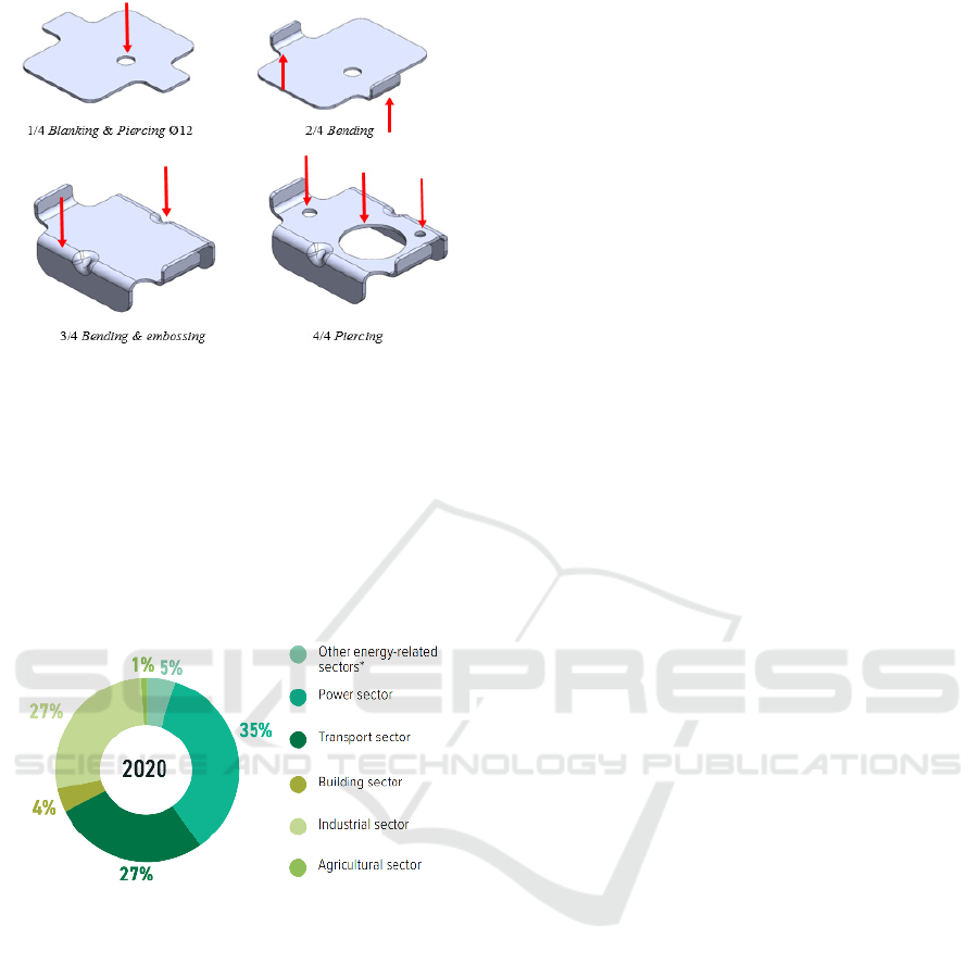
Figure 2: Stages of the process of making the Reinf-FR
Towing Pipe component.
Figure 3 shows a graph of the contribution of
various sectors to the amount of CO
2
emissions from
fuel combustion in Indonesia. The industrial sector
is in the top three positions, contributing the most
CO
2
emissions, 27%. This is related to the large
number of machines used in the industry. To
overcome this, the concept of green manufacturing
is needed.
Figure 3: CO2 emissions from fuel combustion by sector
in Indonesia (Climate Transparency, 2021).
Green manufacturing is a process or system that
does not have a negative impact on the environment
(Dornfeld, 2013). To reduce or eliminate the
negative effects of the manufacturing process, lean
manufacturing can be done. Lean manufacturing is
streamlining the production process by considering
all resource expenditures to produce products with
economic value without waste (Sundar et al., 2014).
It is considered to be the most influential in
manufacturing as empirical evidence that enhances
organisational competitiveness (Ikatrinasari et al.,
2018). Eight things cause production wastage:
transport, inventory, motion, waiting,
overproduction, over-processing, defects, and
unutilised talent (Leksic et al., 2020).
Improvement tools for manufacturing vehicle
components can reduce the eight wastes in the
manufacturing process. Eco-design is one way to
implement green manufacturing. Casamayor and Su,
(2021) assessed each LED lighting production
process. One of the processes that implement eco-
design on products is optimising the amount of
material used via simulation and optimisation, in
that case, using SolidWorks simulation. Using the
eco-design concept, the production process of
vehicle components also can be faster and reduce the
use of raw materials for tool making and press
machines. Therefore, a tool improvement design was
carried out to manufacture a Reinf-FR Towing Pipe
using the tool group. It combines 2-3 types of work
on a single die set, single operation. Usually, this
tool group has no more of the two operations
(Budiarto, 2012). Tool build, cost calculation, and
tool life are not discussed. Currently, three machines
are needed to produce the Reinf-FR Towing Pipe.
By grouping multiple processes into one tool, only
one machine is required.
2 METHODS
The VDI 2222 (Verein Deutsche Ingenieur) and ISO
14006:2011 methods are used to design a group tool
because this method is suitable for the product
development process based on eco-design. By using
this method, scrap and cycle times are expected to
be reduced. (Budiarto et al., 2022; Navajas et al.,
2017). By reducing cycle time, energy consumption
is also reduced. This method consists of 4 main
stages, planning, conceptualising, designing and
completion. Figure 4 shows the flow process of VDI
222.
In the planning stage, the first step is to analyse
and identify the product so that a product
requirement is generated (Sianipar et al., 2013). As a
result of the product analysis, the cutting-forming
process stages will be determined to produce
products according to the specifications on the
product working drawings. Tool design was
developed using the layout process design for each
function part of the tool. After the layout process is
completed, a draft will eventually be detailed into an
Assembly drawing and components drawing.
Finally, the cycle time of the product production
process is investigated to ensure that the design
made is an eco-design.
The Implementation of Eco-Design Through Group Tool Design for Reinf-FR Towing Pipe Products
943
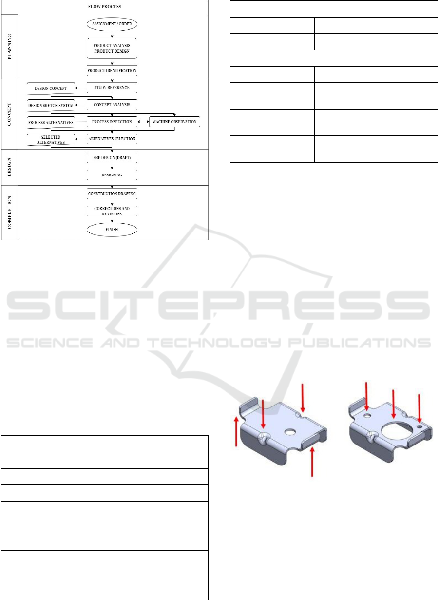
Figure 4: VDI 2222 Methods.
3 RESULTS AND DISCUSSIONS
3.1 Planning
Eco-design must be employed in the development of
the tool designed. It is expected to reduce cycle time
and production costs without compromising product
quality. The production costs can be reduced by
minimising the number of operators and machines.
Table 1 shows the list of design requirements that
have been compiled.
Table 1: Design Requirements.
Design Requirement
Demands Qualification
Product
Product dimension According to the 3D model
Thickness 2.3 mm
Grade SAPH440-P
Tensile Strength 440 N/mm²
Tool
Assy Process Easy for maintenance
Clamping System Strap clamp
Design Requirement
Demands Qualification
Standard Components MISUMI
Machine
Machine capacity Min. 120% of tool Force
Ram Dimension
Min. equal with an upper plate of
the tool
Bolster dimension
Min. equal with a lower plate of
the tool
Die height
Min. equal to a total height of the
tool
3.2 Concepting
A construction design concept is developed based on
the design requirements. The punch forming and
piercing are located in the upper assembly of a push-
through design, while the die is located in the lower
assembly. Considering the limited space in this
construction, no button die is used in the piercing
process. A push-through mechanism is used to
ensure scrap falls to the lower plate (Budiarto et al.,
2022).
The process involves merging the same two
processes in one station and creating a tool group
consisting of two stations. The first station is used
for u-bending and embossing, while the second
station is used for piercing. Figure 5 shows the
process from each station.
(a) (b)
Figure 5: (a) Station 1: u-bending and embossing (b)
Station 2: piercing.
As part of the process layout, a punch is also
used as a blank holder to hold the material flow rate.
The punch will form the U-bend first and then, when
bottoming, act as a stripper for the second bending
and embossing (Patriatna & Budiarto, 2015). Figure
6 shows the design construction from the front and
side views.
iCAST-ES 2022 - International Conference on Applied Science and Technology on Engineering Science
944
(a)
(b) (c)
Figure 6: Design construction (a) front view of station 1
(left) and station 2 (right); side view (b) station 1 (c)
station 2.
3.3 Design Calculation and Control
Processes
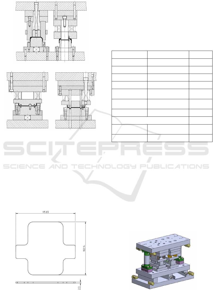
3.3.1 Blank Calculation
SolidWorks software was used to perform a blank
calculation using the K-factor and neutral axis
settings. Figure 7 shows the blank from the software
calculation.
Figure 7: Blank from Software calculation.
3.3.2 Press Tonnage Calculation
Machine control calculations are performed to
ensure that the force required by the tool is
consistent with the machine being used. Table 2
shows the press tonnage calculation.
Table 2: Press tonnage calculation (Budiarto, 2012; Heinz
Tschaetsch, 2015; Rahmi, 2021).
Parameter Equations Result
Piercing Force = 0.8 · l · s · Rm 127.1 kN
Bending Force
= (1.7 · B · s
2
· Rm) / L
5.7 kN
Embossing Force = A proj . Kr 92.2 kN
Penetration = (1 ~ 3) · s 3,5 mm
Stripper Forming
Force
= 10% · F Process
9.68 kN
Stripper Piercing
Force
= 10% · F Process
12.71 kN
Pad Force
= (30 ~50) % (Fb + W)
0.342 kN
Total Tool Force 247.68 kN
Clearance = s · c
0.15 mm/
side
Machine capacity
= 120% · F tool
29,7 Ton
The press machine used is AIDA NC 1-1500 (2)
E, one of the references in selecting the minimum
press machine that can be used is the machine
tonnage based on calculations. Once the tonnage of
the press machine has been calculated based on the
required machine force, the dimensions of the ram
and bolster should be examined. The die height of
the machine must be taken into consideration if the
dimensions of the ram and bolts have been met.
Completion. The draft that has been made is then
converted into a 3d model and developed into an
Assembly drawing and parts. Figure 8 shows the 3D
model of the group tool for the Reinf-FR Towing
Pipe.
Figure 8: 3D model of group tool Reinf-FR Towing Pipe.
The Implementation of Eco-Design Through Group Tool Design for Reinf-FR Towing Pipe Products
945

3.4 Cycle Time Investigation
Further, the estimated processing time is calculated
to predict the products that can be completed in one
cycle. Table 3 shows the results of the cycle time
comparison.
Table 3: The comparison of cycle time.
Type of Tool
Cycle
Time
(seconds)
Setting
time
(seconds)
Time
Process +
Time
setting
Single tool 1 8 3.600 3.608
Single tool 2 12 3.600 3.612
Single tool 3 8 3.600 3.608
Total 10.828
Group Tool 15 3.600 3.615
Reduction Time (second) 7.213
Based on the calculation of processing time,
group tool can reduce the processing time by almost
66%. Furthermore, efficiency can also be measured
by the number of machines used. The existing
process requires three machines to produce the same
product, but only one machine will be required if
this tool is used. The reduction of the number of
machines and the cycle time of the process will also
reduce the electrical energy consumption.
4 CONCLUSIONS
A 260 mm x 386.3 mm x 550 mm tool group has
been produced for Reinf-FR Towing Pipe
components considering VDI 2222 methods and
eco-design. The group tool is designed using a push-
through system, station 1 forming (bending and
embossing), and at station 2 a piercing process, then
processed by an AIDA NC 1-1500 (2) Press
Machine. Moreover, with this group tool design, the
processing time can reduce almost 66%.
REFERENCES
Budiarto. (2012). Press Tool 1-3. Polman Bandung.
Budiarto, H. A., Permana, S., Yuliar, Y. E., & Hasyim, A.
P. (2022). Analisis produk dan perancangan
combination tool pada produk jam souvenir Polman
Bandung. Dinamika Teknik Mesin, 12(1), 66–77.
https://dinamika.unram.ac.id/index.php/DTM/article/v
iew/511/pdf
Casamayor, J. L., & Su, D. (2021). Investigation of a
process to eco-design led lighting products.
Sustainability (Switzerland), 13(8).
https://doi.org/10.3390/su13084512
Doni. (2021). Kebijakan PPnBM Dongkrak Penjualan
Otomotif Hingga Lebih Dari 60 Persen. KOMINFO.
https://www.kominfo.go.id/content/detail/38166/kebij
akan-ppnbm-dongkrak-penjualan-otomotif-hingga-
lebih-dari-60-persen/0/berita
Dornfeld, D. (2013). Green manufacturing: Fundamentals
and applications. Green Manufacturing: Fundamen-
tals and Applications, 9781441960160, 1–289.
https://doi.org/10.1007/978-1-4419-6016-0
Heinz Tschaetsch. (2015). Metal Forming Practice. In
Syria Studies (Vol. 7, Issue 1). https://www.research
gate.net/publication/269107473_What_is_governance/
link/548173090cf22525dcb61443/download%0Ahttp:/
/www.econ.upf.edu/~reynal/Civilwars_12December20
10.pdf%0Ahttps://think-asia.org/handle/11540/8282%
0Ahttps://www.jstor.org/stable/41857625
Ikatrinasari, Z. F., Hasibuan, S., & Kosasih, K. (2018).
The Implementation Lean and Green Manufacturing
through Sustainable Value Stream Mapping. IOP
Conference Series: Materials Science and
Engineering, 453(1). https://doi.org/10.1088/1757-
899X/453/1/012004
Kurniawan, R. (2022). Penjualan Mobil Indonesia
Terbesar di ASEAN Sepanjang 2021. Kompas.Com.
https://otomotif.kompas.com/read/2022/02/10/120200
715/penjualan-mobil-indonesia-terbesar-di-asean-
sepanjang-2021?page=all
Leksic, I., Stefanic, N., & Veza, I. (2020). The impact of
using different lean manufacturing tools on waste
reduction. Advances in Production Engineering And
Management, 15(1), 81–92. https://doi.org/10.14743/
APEM2020.1.351
Navajas, A., Uriarte, L., & Gandía, L. M. (2017).
Application of eco-design and life cycle assessment
standards for environmental impact reduction of an
industrial product. Sustainability (Switzerland), 9(10).
https://doi.org/10.3390/su9101724
Patriatna, E., & Budiarto, H. A. (2015). Perancangan
Combination Tool Proses Cutting Dan Forming Pada
Pembuatan Alumunium Cup. Jurnal Politeknik
Manufaktur Negeri Bandung, 2(1).
Rahmi, M. (2021). Comparative Analysis of Press Tool
Design for Seat Lock Patch of Mobilio Car with
AutoForm Technology.
208(Icist 2020), 316–320.
Sianipar, C. P. M., Yudoko, G., Dowaki, K., &
Adhiutama, A. (2013). Design methodology for
appropriate technology: Engineering as if people
mattered. Sustainability (Switzerland), 5(8), 3382–
3425. https://doi.org/10.3390/su5083382
Sundar, R., Balaji, A. N., & Satheesh Kumar, R. M.
(2014). A review on lean manufacturing implemen--
tation techniques. Procedia Engineering, 97, 1875–
1885. https://doi.org/10.1016/j.proeng.2014.12.3 41
iCAST-ES 2022 - International Conference on Applied Science and Technology on Engineering Science
946
