
Designing Features of Applied Ontology of Integrated Expert
Systems’ Typical Architectures Using the Intelligent Software
Environment of the AT-TECHNOLOGY Workbench
Galina V. Rybina
a
, Alexandr A. Slinkov
b
and Andrey A. Grigoryev
c
Department of Cybernetics, National Research Nuclear University «MEPhI», Kashirskoe highway, Moscow, Russia
Keywords: Integrated Expert Systems, IES, Intelligent Software Environment of the AT-TECHNOLOGY Workbench,
Technological Knowledge Base, Applied Ontology of Typical IES Architectures, SDP, RUC, Tutoring IES.
Abstract: A new stage of experimental research is described, devoted to the application of an ontological approach to
automate the design of software for various classes of intelligent systems, in particular, integrated expert
systems (IES) developed on the basis of an original problem-oriented methodology and an intelligent software
environment of the AT-TECHNOLOGY workbench. The main emphasis is on the features of building an
extended technological knowledge base by including a new component in its composition in the form of an
applied ontology of typical IES architectures, which provides a logical interconnection of all components of
the technological knowledge base and effective interaction with an intelligent planner in the process of
prototyping IES. As an example, a fragment of an applied ontology of typical architectures, constructed for
tutoring IES, is given.
1 INTRODUCTION
The concept of the ontology of standard architectures
of integrated expert systems (IES) (Rybina, 2021) is
an evolution of the problem-oriented methodology
for designing IES and the intelligent software
environment of the AT-TECHNOLOGY workbench
(Rybina, 2008), designed to automate and
intellectualize software design processes of various
classes of IES, especially at time-consuming stages of
system analysis.
A complete description of the considered
methodology and technology of designing and
developing applied IES is given (Rybina, 2008), and
it is necessary to indicate that the principal feature of
this methodology is the conceptual and software
modelling of the architectures of the developed IES at
each level of integrational processes in the IES, which
is effectively supported by the powerful functionality
of the intelligent planner using great opportunities of
the technological knowledge base (KB) (Rybina,
2019), which includes a huge set of specifications of
a
https://orcid.org/0000-0002-4077-3660
b
https://orcid.org/0000-0002-8688-4163
c
https://orcid.org/0000-0003-1188-6815
different standard design procedures (SDP) for the
design of the most common IES architectures (static,
dynamic and tutoring IES), a set of operational and
information reusable components (RUC), as well as
an applied ontology of typical IES architectures.
The main prerequisites for the expansion of
technological KB by creating an ontology of different
typical IES architectures were, on the one hand, a
significant amount of accumulated information and
software of various classes of IES developed in recent
years, and on the other hand, in the context of
interaction with an intelligent planner, the need to
reduce the accessibility to semantically
heterogeneous RUC with implicit functionality when
their search and initialization in the conditions of the
implementation of a specific SDP.
In general, if we consider new approaches to
automation and intellectualization of software system
design processes using or under the control of
ontologies (Rybina, 2021), then the place and role of
ontologies here is significantly determined by the
level of complexity of the architecture models of the
452
Rybina, G., Slinkov, A. and Grigoryev, A.
Designing Features of Applied Ontology of Integrated Expert Systemsâ
˘
A
´
Z Typical Architectures Using the Intelligent Software Environment of the AT-TECHNOLOGY Workbench.
DOI: 10.5220/0011951100003612
In Proceedings of the 3rd International Symposium on Automation, Information and Computing (ISAIC 2022), pages 452-456
ISBN: 978-989-758-622-4; ISSN: 2975-9463
Copyright
c
2023 by SCITEPRESS – Science and Technology Publications, Lda. Under CC license (CC BY-NC-ND 4.0)
systems being developed, the availability of adequate
life cycle models (LC) and semantically correct
reflection of the basic design processes at all stages of
LC taking into account the ontological representation
of the projected architecture, composition, structure
and specifications of individual components and the
relationships between them.
Nevertheless, despite a wide range of works on
ontological engineering (Calero, 2006), (Happel,
2006), (Bossche, 2007), (Jabar, 2019), (Horoshevskij,
2019), (Erzhenin, 2020), (Negoda, 2021), etc., issues
related to the development of a significant and
semantically adequate ontological model of software
system design processes, in particular, intelligent
systems, are poorly considered. So the expansion of
research in the framework of intelligent technology
creation for designing an IES as a common class of
intelligent systems with extended scalable
architectures is especially important today, including
the details of combining the methods of intelligent
planning with an ontological approach (Rybina,
2019).
This paper discusses the results of an
experimental software study of the actual structure of
the considered in main theme applied ontology, the
model and design methods of which allow us to
jointly take into account the semantic features of the
architecture models of the designed IES and the
features of component-by-component functionality in
the form of a set of RUCs for each SDP. It should be
noted that since the greatest number of software
components and tools that have been tested and
reengineered as part of the AT-TECHNOLOGY tool
workbench and designed in the form of operational
and information RUCs have been accumulated for the
implementation of the tutoring IES architectures, the
corresponding SDP "Designing tutoring IES and
web-IES" was selected as the base test field for
various studies and experimental software modelling.
2 BRIEF DESCRIPTION OF THE
ONTOLOGY MODEL AND
FEATURES OF APPLIED
ONTOLOGY DESIGN
As it was shown in (Rybina 2021), the choice of the
basic model of the ontology of typical architectures
was greatly influenced by the positive experience of
creating several ontologies of courses/disciplines for
tutoring and practical use in the educational process,
the development of which was carried out on the basis
of a model in the form of a semantic network of a
special type (Rybina, 2017), (Rybina, 2022).
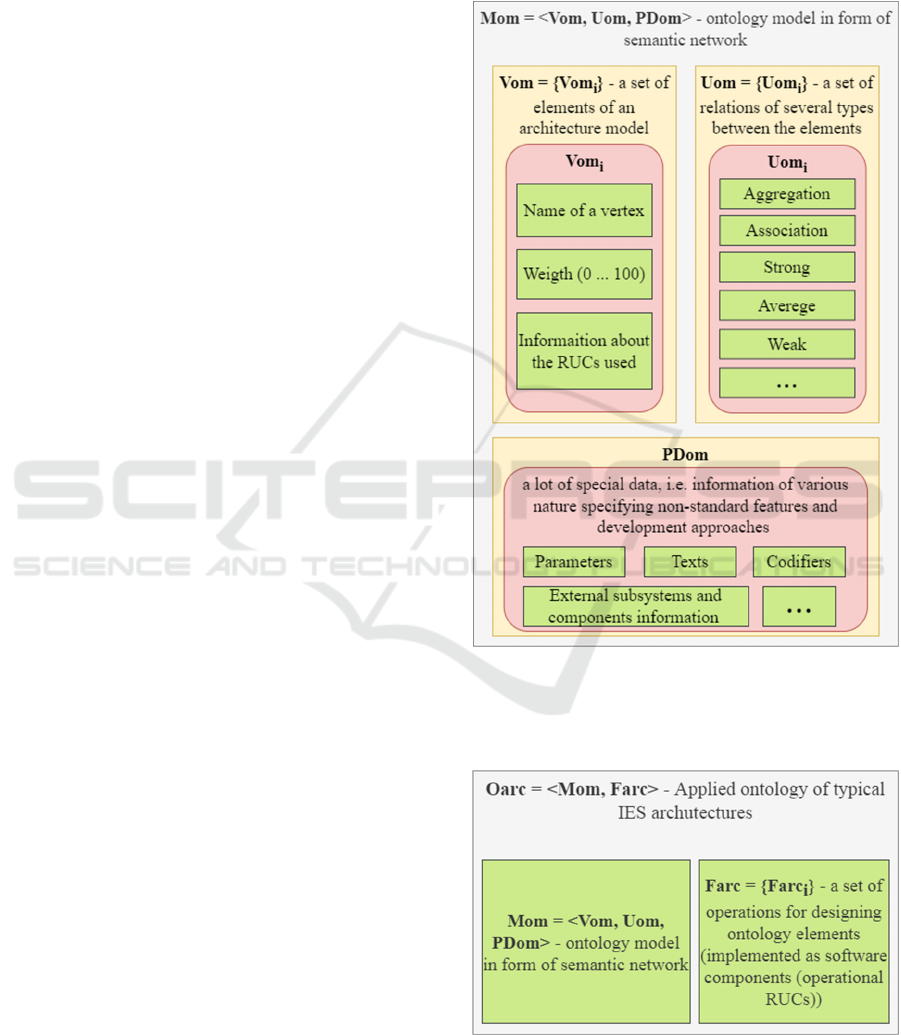
Therefore, a modified semantic network is used
here as an ontology model, but of a simpler form
(Rybina, 2021) (Figure 1):
Figure 1: Ontology model in from of semantic network.
Accordingly, the actual applied ontology (Rybina,
2021) is reproduced in the form, shown on Figure 2:
Figure 2: Applied ontology.
Designing Features of Applied Ontology of Integrated Expert Systemsâ
˘
A
´
Z Typical Architectures Using the Intelligent Software
Environment of the AT-TECHNOLOGY Workbench
453

Now let's briefly consider some aspects of
designing the actual version of the applied ontology
of various typical IES architectures, the main purpose
and purpose of which is to take into account and
reflect at different levels of the ontology the features
and logical relationships of the architecture model of
the projected IES, as well as the specification of
methods and algorithms implemented in the
corresponding RUC.
It should be noted here that the architecture model
of the prototype of the IES, represented in the form of
a hierarchy of extended data flow diagrams (EDFD)
(Rybina, 2008), is one of the important components
of the process of prototyping of the IES, due to the
fact that its order has a strong effect on the prototype
of the IES and its capabilities for the implementation
of a specific class of tasks to be solved. The
emergence of architectural elements at different
levels of nesting due to the implementation of multi-
level integration processes reproduced in the EDFD
hierarchy required the use of different non-trivial
approaches and solutions, including a set of plural
information and operational RUCs included in
various software tools of the AT-TECHNOLOGY
workbench.
Therefore, the general structure and basic levels
of the considered applied ontology are given in
(Rybina, 2021), as well as connection (relation) types
presented in that research and at Figure 1 above.
Taking into account these conceptual and
functional features of IES prototyping (Rybina
2008), (Rybina, 2019), all algorithms and procedures
for designing, storing and maintaining the considered
in main title applied ontology as an significant section
of the technological KB were developed in such a
way as to make the possibility of access and
comprehensive customization the appropriate RUC to
perform all planned tasks with the help of an
intelligent planner, depending on the features of the
model the architecture of the designed IES (at the
same time, a knowledge engineer can perform some
tasks independently or jointly with an expert).
For automated support of the processes of
designing an applied ontology of typical IES
architectures, modified tools were used that function
as part of the basic tools of the AT-TECHNOLOGY
workbench and allow to fully implement the
necessary functionality, as well as for modeling
interaction with an intelligent planner (Rybina, 2019)
developed tools for managing interaction with
technological KB were involved.
3 APPLIED ONTOLOGY OF
TYPICAL IES
ARCHITECTURES
FRAGMENT’S EXAMPLE (SDP
"DESIGNING TUTORING IES
AND WEB-IES")
As an example, we will give a fragment of the applied
ontology of typical IES architectures, which shows
the conceptual (logical) and program relationship
between the set of standard processes for tutoring IES
related to displaying the current student model, built
as a result of web testing, on the ontology of a specific
course/discipline and the formation of an individual
strategy (plan) depending on the results obtained
tutoring type (Rybina, 2008), (Rybina, 2017).
As noted above, the overall management of these
and other processes in the two basic modes of
operation of tutoring IES (DesignTime and RunTime)
(Rybina, 2008), (Rybina, 2019), (Rybina, 2017) is
supported by an intelligent planner, the SDP
"Designing tutoring IES and web-IES" and a set of
RUC implemented using a significant amount of
various software and information tools registered in
different years in the AT-TECHNOLOGY
workbench and included in the subsystem of support
for the design of tutoring IES.
Therefore, issues related to preliminary analysis,
structural and functional identification and formal
representation of all software tools and components
in accordance with the basic RUC model are of great
importance for designing an applied ontology of
typical IES architectures (Rybina 2008). Below are
the formal descriptions (concretizations) of two
conceptually related RUC implementing the
functionality mentioned above.
Specification of the RUC "Mapping the current
student model to the ontology of the
course/discipline" in accordance with the basic model
of the RUC <N, Arg, F, PINT, FN> (Rybina, 2008) is
defined as:
N - the name of the registered component
"Mapping the current model of the student on the
ontology of the course/discipline";
Arg = <Arg1, Arg2>, where Arg1 is the
course/discipline ontology, (previously built in
DesignTime mode (Rybina, 2008), (Rybina, 2017));
Arg2 - current student model (M1cur);
F: Arg1 х Arg2 → R - method for evaluating the
results of testing students, where R = {rj}, (j = 1÷m)
- a set of "problem areas" of a particular student
(Rybina, 2008), (Rybina, 2017);
ISAIC 2022 - International Symposium on Automation, Information and Computing
454
PINT - RUC interface "Formation of tutoring
strategies";
FN - the function of forming the current level of
the student’s competencies (Rybina, 2017).
So, the specification of the RUC "Formation of
tutoring strategies" is defined as:
N - the name of the registered component
"Formation of tutoring strategies";
Arg = <Arg1, Arg2>, where Arg1 = {arg1i} is the
set of course/discipline ontologies, (i=1÷n), (n is the
number of course/discipline ontologies);
Arg2={arg2j} - set M1tech, (j=1÷p) where p -
number of M1tech;
F = <F1, F2>, where F1: Arg1 х Arg2 → A -
method of forming a set of tutoring strategies (plans),
where A = {ai} (i=1÷k) - set of tutoring plans, where
k is the number of plans; F2: Arg1 × A → B is a
method for generating a set of learning influences
based on plans, where B = {Bi}(i=1÷m) is a set of
learning influences, where m is the number of
learning influences;
PINT - RUC interface "Management of the
implementation of learning influences";
FN - formation of a set of tutoring strategies
containing an ordered set of learning influences.
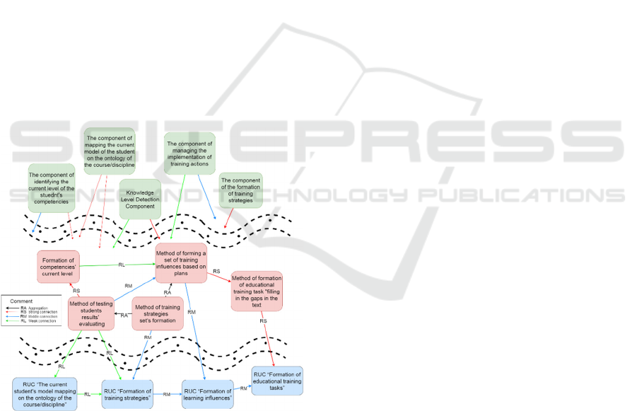
Figure 3: Fragment of the applied ontology.
Figure 3 shows a fragment of the applied ontology
of typical IES architectures, the upper levels of which
reflect the functional and structural features of the
subsystem for supporting the design of tutoring IES,
which operates in the basic version of the AT-
TECHNOLOGY workbench (Rybina, 2008),
(Rybina, 2017). The middle and lower levels of the
ontology are formed on the basis of formal
specification of the RUC.
The greatest variety of connections is observed at
the levels of methods/operations, where such types of
connections are used, such as, for example,
connections of the RA type (aggregation) between the
method of forming a set of learning influences and the
method of forming a set of tutoring strategies, as well
as connections of the RS type (strong) between the
method of formation of educational training task
"Filling in the gaps in the text” the RUC “Formation
of educational training tasks” and others.
4 CONCLUSION
The ongoing research and experimental software
modeling of software design methods for applied
power plants with various architectural typologies
under the control of ontologies are quite new for
artificial intelligence technologies and software
engineering in general.
It is too early to expect practical results in the field
of creating effective ontological models and powerful
tools and platforms for automating and
intellectualizing software development processes of
intelligent systems. Nevertheless, the accumulated
experience and the constantly developing
technological base in the form of the environment of
the AT-TECHNOLOGY workbench allow us to
solve the scientific and practical tasks set in stages.
REFERENCES
Rybina G. V., Slinkov A. A. The Implementation of the
Ontological Approach to Control of the Processes of
Designing Integrated Expert Systems Based on the
Problem-Oriented Methodology. // Artificial
Intelligence. 19th Russian Conference, RCAI 2021,
Taganrog, Russia, October 11-16, 2021. Proceedings.
Springer Nature Switzerland AG 2021. pp. 354-364.
Rybina G. V. Teoriya i tekhnologiya postroeniya
integrirovannyh ekspertnyh sistem. Monografiya. – M.:
Nauchtekhlitizdat, 2008.
Rybina G. V., Blokhin Y.M. Methods and Software
Implementation of Intelligent Planning for Integrated
Expert System Design // Scientific and Technical
Information Processing, 2019, 46 (6), pp. 434 - 445
Ontologies for Software Engineering and Software
Technology. 1st Ed. / C. Calero, F. Ruiz, M. Piattini –
Springer, 2006.
Happel H.J. KOntoR: An Ontology-enabled Approach to
Software Reuse / H.J. Happel, A. Korthaus, S. Seedorf,
P. Tomczyk // Proc. SEKE 2006: the 18th International
Designing Features of Applied Ontology of Integrated Expert Systemsâ
˘
A
´
Z Typical Architectures Using the Intelligent Software
Environment of the AT-TECHNOLOGY Workbench
455

Conference on Software Engineering & Knowledge
Engineering (July 5-7, 2006, California, USA, 2006).
Bossche M.V. Ontology Driven Software Engineering for
Real Life Applications / M.V. Bossche, P. Ross, I.
MacLarty, B. van Nuffelen, N. Pelov // Proc. 3rd
International Workshop on Semantic Web Enabled
Software Engineering, SWESE 2007 (Innsbruck,
Austria, 2007).
Jabar M.A. General Domain Ontology in Enterprise
Software Development Process / M.A. Jabar, M.S.
Khalefa // International Journal of Engineering and
Advanced Technology. – 2019. - Vol. 8, Is. 3S.
Horoshevskij V.F. Proektirovanie sistem programmnogo
obespecheniya pod upravleniem ontologij: modeli,
metody, realizacii //Ontologiya proektirovaniya. 2019.
T.9. №4. S.429-448.
Erzhenin R.V., Massel' L.V. Ontologicheskij podhod k
predstavleniyu znanij o metodologii modelirovaniya
slozhnoj sistemy upravleniya. // Ontologiya
proektirovaniya. 2020. T.10.№4.S. 463-474.
Negoda V. N.,Kulikova A.A. Skvoznoe proektirovanie
avtomatizirovannyh sistem na osnove ontologij //
Ontologiya proektirovaniya. 2021.T.11.№4.S.450-463.
Rybina G. V. Intellektual'naya tekhnologiya postroeniya
obuchayushchih integrirovannyh ekspertnyh sistem:
novye vozmozhnosti // Otkrytoe obrazovanie. 2017.
№4. S. 43-57.
Rybina G. V., Nikiforov A. Y., Slinkov A. A., Grigoryev
A. A. Automated Formation of the Unified Ontological
Space of Students’ Knowledge and Skills to Implement
Intellectual Tutoring Tasks Based on Tutoring
Integrated Expert Systems. // 2022 VI International
Conference on Information Technologies in
Engineering Education (Inforino), 2022, pp. 1-6.
ISAIC 2022 - International Symposium on Automation, Information and Computing
456
