
Safe and Secure Shaft to Support Robotic Hand on Live Line
Operation
Ni Putu Susri Aprilian Iriani, I Wayan Jondra and I Nengah Sunaya
Electrical Department, Politeknik Negeri Bali, Jalan Kampus Bukit Jimbaran, Kabupaten Badung, Indonesia
Keywords: Safe, Live Line, Secure.
Abstract: The biggest problem that can affect the stability and reliability of the power system is a disturbance.
Disruption of the electric power system can be caused by two factors, namely internal (ex: Pin Insulator
rupture) and external factors (ex: animals). In particular moments outages may occur and cause by animals
such as birds, squirrels, and snakes. Reducing the outage requires periodic maintenance in order to overcome
such interference by installing Tekep Isolator. When first introduced Tekep Isolator was very effective to
overcome the momentary interruption / permanent caused by animals, but the job requires considerable time
and shut off the electric power. To cope with blackout feeders for the installation of the Tekep Isolator, then
made the tool post Tekep Isolator. The results of a comparative analysis of the installation work insulator caps
with and without blackout obtained significant savings. So, this tool is very useful if it is implemented in PT
PLN (Persero) Region Bali and other areas that use the same type of Tekep Isolator. The shaft's insulation
value is more than 100 Giga Ohm, the leakage current is lower than 1 milliampere, the dielectric strength is
more than 11.6 kV, and the worker distance to live parts is more than 60 cm to make the system a safe state.
1 INTRODUCTION
Electrical energy is one of the important factors in the
development of every nation, including Indonesia.
Electrical energy has an important role for
development in both economic and social aspects.
Currently in Indonesia the only distribution of
electrical energy is PT PLN (Persero). In the
distribution of electrical energy, it is expected that the
maximum power is channeled, so that consumers and
producers feel comfortable. The electrical energy
distribution system must have high reliability which
aims to maintain the quality and continuity of
electrical energy distribution (Fatmawati, 2021).
Reliability is a key word as a guarantee of the
continuity of electricity supply to customers. The
reliability performance in question is determined by
the low number of SAIFI (System Average
Interruption Frequency Index), SAIDI (System
Average Interruption Duration Index) and ENS
(Energy Not Sale) (Sumper et al., 2004). Based on
SPLN 59 of 1985, the permitted SAIFI is 1,199
times/year and the permitted SAIDI is 1.75
hours/year.
The Tekep Isolator is the brand of many insulator
cover, gives chance to PLN to overcome natural
disturbances in the all aluminum alloy conductor
shield (A3CS) network caused by trees, animals,
weather and so on. Tekep Isolator is a safety
component of the medium voltage air distribution line
(SUTM) network. The insulator tack is a component
that functions to protect the tensile insulator, prevent
fouling of the supported insulator, as well as to tie the
A3CS conductor to the supported insulator. Tekep
Isolator for substations can overcome phase-to-
ground faults (Fan et al., 2021). If a single phase to
ground fault occurs, it will interfere with the other
two healthy phases in a three phase system (Fan et al.,
2021)
In the installation of the insulator using a robotic
arm with on the live line work method it is chance to
reduce the value of SAIDI and SAIFI on the
performing distribution network maintenance and
providing the best service for customers. This paper
discusses the test result the shaft of the insulator
clamp installation tool with robotic hands for live line
work safety on A3CS cables in medium voltage
distribution.
Iriani, N., Jondra, I. and Sunaya, I.
Safe and Secure Shaft to Support Robotic Hand on Live Line Operation.
DOI: 10.5220/0011880400003575
In Proceedings of the 5th International Conference on Applied Science and Technology on Engineering Science (iCAST-ES 2022), pages 781-786
ISBN: 978-989-758-619-4; ISSN: 2975-8246
Copyright © 2023 by SCITEPRESS – Science and Technology Publications, Lda. Under CC license (CC BY-NC-ND 4.0)
781
2 RESEARCH METHODE
2.1 Research Approach and Concept
To analyze these problems, this study was designed
as a research with a qualitative approach. These
problems will be discussed from measurement and
test data, equipment calculations to obtain good
insulation for medium voltage work safety shaft, and
all connected components. This research was piloted
at PT. Adi Putra, and the test results were analyzed
statistically and mathematically to obtain the
feasibility of a 20kV shaft tool for electrical safety,
compare the role of electrical work safety, and then
draw conclusions and recommendations.
2.2 Total Sample
This research was conducted by tested one sample on
a shaft, tasted 6 data for each indicator. Data
collection was carried out by testing the wet and dry
conditions and measuring the value of the voltage and
leakage current flowing into the water rheostat
2.3 Variable Operational Definition
In testing the feasibility of this robot hand tool,
leakage current, insulation test, dielectric strength and
clearance were also observed. This test is carried out
by applying a voltage of 5,000 Volts and 10,000 Volts
to the head and handle terminals. The test voltage is
the amount of voltage applied to the sample through
a high voltage tester. Leakage current is the amount
of current flowing into the test sample, due to the
given test voltage. Dielectric distance and clearance
are measured with a ruler meter.
2.4 Data Analysis
Data obtained from the test results are processed
quantitatively. The data is processed mathematically
by the process of multiplication and division. The data
is also processed statistically by finding the smallest
value of all data if the limits are minimum such as
insulation resistance, dielectric strength, space
clearance, and finding the largest value of all data if the
maximum limit is such as in leakage. current condition.
3 RESULT AND DISCUSSION
The results of this study are illustrated by pictures and
tables. The analysis of the feasibility of the shaft as a
robot hand operation tool was carried out to ensure
work safety. Robotic hand tools must have good
insulating resistance and insulated shafts to ensure
work safety in construction, maintenance, repair and
upgrading of medium-voltage distribution. However,
no material is perfect, therefore research on this
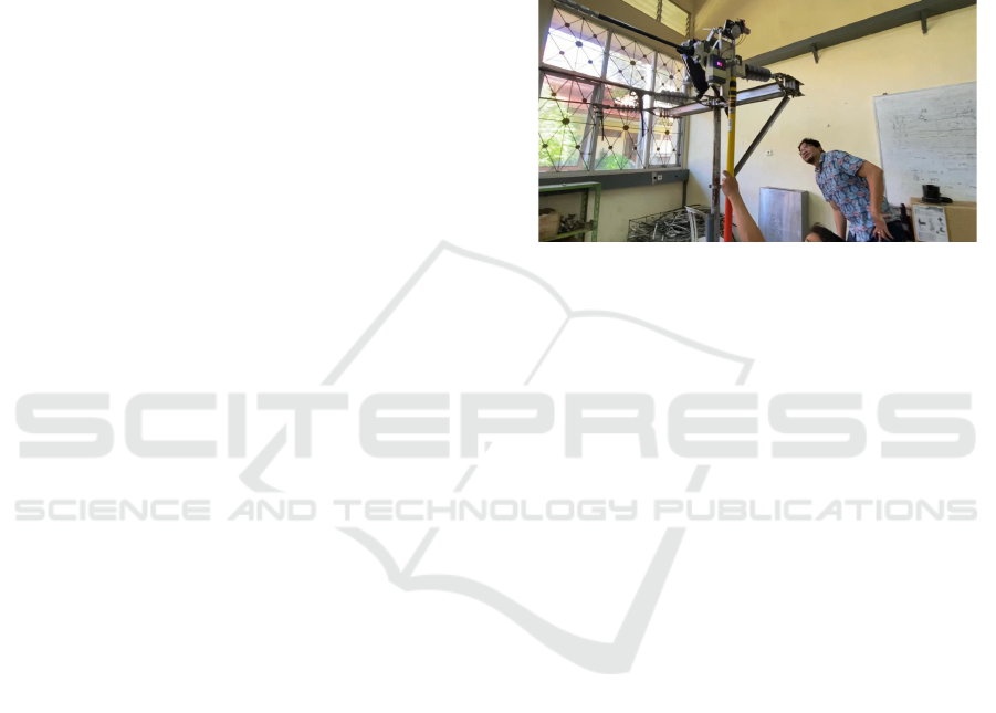
feasibility test is very important. This 20kV shaft is
made of polypropylene pipe, which has good
electrical characteristics because its volume
resistivity coefficient is 8.5x10
14
Ohm-cm.
Figure 1: 20kV Shaft as robot hand operation tools.
The perfect insulating material has an infinite
resistance, which is currently not obtainable. There is
a small leakage current flowing in the insulating
material and it can be shown as below equation (Amin
& Amin, 2011).
V = I x R (1)
R = V / I (2)
where:
R = Insulating Resistance (Giga Ohm)
V = Voltage charge due the sample (Kilo Volt)
I = Leakage Current (microampere)
The normal air dielectric strength coefficient is 30
kV/cm, the total dielectric strength is total distance
multiple with dielectric strength coefficient, as shown
in the formula below (Kharal et al., 2018).
ℰ =ℰ
0
x d (3)
where:
ℰ = Dielectric strength (KV)
ℰ
0
= Dielectric strength coefficient (KV/cm)
d = distance (cm)
3.1 Result
The minimum insulation for medium voltage is 100
Mega Ohms (Post et al., 2020). The maximum
leakage current flow does not affect a shock to the
human body is 1 milli amperes (Saba et al., 2014).
Total the dielectric strength must exceed than the
iCAST-ES 2022 - International Conference on Applied Science and Technology on Engineering Science
782
active voltage to avoid the electric discharge (Saba et
al., 2014). The minimum safe distance between
workers and 15,000 Volt active equipment is 90 cm
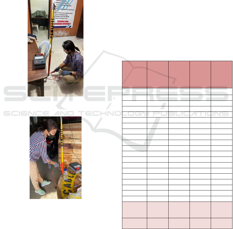
(Ghosh et al., 2015). This Insulation Resistance Test
is carried out to detect the quality of the 20kV shaft
insulation resistance. This test is carried out by
applying a voltage of 5,000 Volts and 10,000 Volts to
the head and handle terminals. The insulation
resistance test was carried out in dry and wet
conditions ten times, the wet condition test as shown
in figure 3.
Figure 2: Dry insulation resistance test with Megger 10,000
Volt.
Figure 3: Wet insulation resistance test with Megger 10,000
Volt.
Tests were carried out using 5000 Volt and 10,000
Volt meggers. The results of the insulation resistance
test using a megger are analyzed to get the leakage
current, as calculated below.
1. Analysis of leakage current at voltage of 5000
Volt
Voltage tested: 5.000 Volt DC
Insulation resistance: 250.000 Mega Ohm
The leakage current calculation:
I = V/R
= 5,000/250,000,000,000
= 0,02x10⁻⁶ amperes
= 0,02 micro amperes
2. Analysis of leakage current at voltage of 10.000
Volt
Voltage tested: 10.000 Volt DC
Insulation resistance: 500.000 Mega Ohm
The leakage current calculation:
I = V/R
= 10000/500,000,000,000
= 0,02x10⁻⁶ amperes
= 0,02 micro amperes
Through the same calculation, the leakage current
as displayed in table 1 at below.
Table 1: Analysis of leakage current of 20kV shaft with
megger 10kV.
Step of
testing
and
condition
R Iso.
at 5 KV
(Giga
Ohm)
R Iso. at
10 KV
(Giga
Ohm)
Leakage
current
at 5 KV
(mA)
Leakage
current
at 10
KV
(mA)
1 dry 250 500 0.0200 0.0200
2 dr
y
275 550 0.0182 0.0182
3 dr
y
290 580 0.0172 0.0172
4 dr
y
300 600 0.0167 0.0167
5 dr
y
310 620 0.0161 0.0161
6 dr
y
330 660 0.0151 0.0151
7 dr
y
370 740 0.0135 0.0135
8 dr
y
390 780 0.0128 0.0128
9 dr
y
430 820 0.0116 0.0116
10 dr
y
440 880 0.0113 0.0113
1 wet 62 124 0.0807 0.0807
2 wet 75 150 0.0667 0.0667
3 wet 80 160 0.0625 0.0625
4 wet 82 164 0.0609 0.0609
5 wet 67 134 0.0746 0.0746
6 wet 73 146 0.0684 0.0684
7 wet 78 156 0.0641 0.0641
8 wet 80 160 0.0625 0.0625
9 wet 65 130 0.0769 0.0769
10 wet 78 156 0.0641 0.0641
Maximum
leakage
current
0.0807 0.0807
Lower
insulation
62 124
Based on the data in table 1, the variation of the
data can be illustrated by the graph in figure 4 below.
Variations in insulation resistance are affected by the
weather at the time of operation.
Safe and Secure Shaft to Support Robotic Hand on Live Line Operation
783
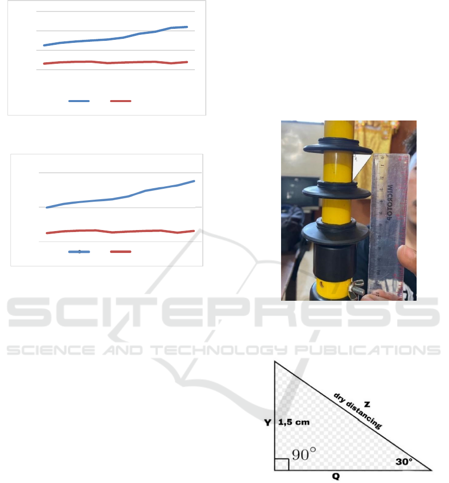
Figure 4: Graph of insulation resistance 5000 volt wet and
dry conditions.
Figure 5: Graph of insulation resistance 10000 volt wet and
dry conditions.
The insulation resistance value of the 20kV shaft
in dry conditions by applying a test voltage of 5000
Volts and 10,000 Volts, one of which is 250 Giga
Ohms and 500 Giga Ohms. The value of the
insulation resistance of the 20kV shaft in wet
conditions by applying a test voltage of 5000 Volts
and 10,000 Volts, one of which is 62 Giga and 124
Giga. This insulation resistance value is obtained
from an average of 10 times the leakage current of the
20kV shaft test. The minimum insulation resistance
of the shaft is more than 100 Mega Ohms. The
minimum insulation benchmark for medium voltage
is 100 Mega Ohm (Post et al., 2020).
The value of the 20kV shaft leakage current in dry
conditions by applying a test voltage of 5000 Volts
and 10,000 Volts of 0.0200 microampere. The value
of the 20kV shaft leakage current in wet conditions
by applying a test voltage of 5000 Volts and 10,000
Volts of 0.0200 micro amperes. So it can be said that
the leakage current is lower than 1 milli Ampere (
Saba et al., 2014). The standard maximum leakage
current that has no effect on shock to the human body
is 1 milli ampere.
To determine a safe electrical working distance,
there are two conditions that must be discussed for a
20kV shaft, namely dielectric strength, total distance
and distance between potential live voltage
equipment and workers when operating a robotic
hand that attaches insulators to medium voltage
equipment.
The rain angle is estimated to be a maximum of
30 degrees. Wet conditions decrease the dielectric
strength. There are 6 rubber rings like an umbrella to
protect the shaft from getting wet. Part of the dry shaft
is protected by a rubber ring to maintain dielectric
strength. Thus, the dielectric strength distance of the
insulator fixing robot hand tool in the tension
insulator clamp can be calculated as described below.
Figure 6: Rubber rings on 20kV shaft as safety.
If the shaded triangle in figure 6 is copied and
pasted, it will be obtained as shown in figure 7 below.
Figure 7: Angle distance.
Dry distancing calculation
Sin Q = Y/Z
Dry Distancing = 1,5/sin 30
= 1,5/0,5 = 3 cm
Total Dry Distancing = 6 x 3 cm = 18 cm
The normal air dielectric strength is 30 kV/cm
(Saba et al., 2014). The total dielectric strength of
grounding shaft with 6 pieces rubber ring is:
ℰ =ℰ0 xd
ℰ = 30 x 18 = 540 KV
0
200
400
600
12345678910
Dry Wet
0
500
1000
12345678910
Dry Wet
iCAST-ES 2022 - International Conference on Applied Science and Technology on Engineering Science
784

The minimum creepage distance on the 20 kv
shaft is 81%, it can be seen through the following
calculation. Total length of shaft= Length of shaft +
total dry distancing
= 300cm + 18cm
= 318cm
Minimum creepage distance of shaft =
Total shaft length - worker grip distance
= 318-60
= 258
Minimum creepage distance= 258/318 x100% =
81%
The total dielectric strength of the 20kV shaft as a
robot hand operation aid with mathematical
calculations is 540 kV. As shown in Figure 4 a 20kV
shaft has a length of 3 meters. Thus the 20kV shaft is
qualified to maintain the distance between the worker
and the active part of the 15 kV phase to the ground
with a minimum distance of 60 cm (Ghosh et al.,
2015). The medium voltage distribution system in
Indonesia is only 11.6 KV lower from phase to
ground.
3.2 Discussion
Based on table 1, it can be seen that the maximum
leakage current value is not more than 1 Ampere and
the minimum insulation resistance of the grounding
shaft is not less than 100 Mega Ohms (Jondra et al.,
2020). The higher the voltage applied to the insulator,
the leakage current value is increased (Negara et al.,
2021). The standard maximum leakage current that
has no effect on shock to the human body is 1 milli
ampere. Based on the results of the safety distance
analysis, two values were obtained for assessing the
feasibility of a 20 kV shaft, namely: the value of
dielectric strength and the distance between workers
and active parts with potential for voltage release.
The analysis found that the 20kV shaft has a
dielectric strength of 540 kV, and provides a safe
distance between workers and live parts of 300 cm.
The total dielectric strength benchmark must exceed
the active voltage to avoid electric discharge (Saba et
al., 2014). The benchmark for the minimum safe
distance between workers and 15 kV active equipment
is a minimum of 60 cm (Ghosh et al., 2015).
4 CONCLUSIONS
The requirements that must be met by the Robot Hand
Installing Insulators in Medium Voltage Air Line Pull
Insulators (SUTM) are that they can be remotely
controlled and are able to close all insulator clamps
perfectly, have a high level of security such as not
delivering electric current to the linesman or work
executors on during operation, the weight of the robot
hand is according to the plan, which is appropriate
and can be easily lifted up and the 20kV shaft tool on
the robot hand is safe for medium voltage distribution
systems with A3CS cables. This feasibility is
determined based on good connection ability, leakage
current, insulation resistance, dielectric strength, and
safety distance. The results show that the shaft
exceeds the specified requirements. The insulation
value is more than 100 Giga Ohm, the leakage current
is lower than 1 milliampere, the dielectric strength is
more than 11.6 kV, and the worker distance to live
parts is more than 60 cm to make the system in a safe
state.
ACKNOWLEDGEMENTS
This research was funded by Lembaga Pengelola
Dana Pendidikan and Direktorat Jenderal Pendidikan
Vokasi Kementrian Pendidikan, Kebudayaan, Riset
dan Teknologi 2021. We thank Director of Politeknik
Negeri Bali for his support to this research and we
thank Project Management Office of Domestic
Vocational Higher Education Program Implementation
of the Applied Scientific Research in 2021 for his
support to this research.
REFERENCES
Amin, S., & Amin, M. (2011). Thermoplastic elastomeric
(TPE) materials and their use in outdoor electrical
insulation. Reviews on Advanced Materials Science,
29(1), 15–30.
Fan, B., Yao, G., Wang, W., Yang, X., Ma, H., Yu, K.,
Zhuo, C., & Zeng, X. (2021). Faulty phase recognition
method based on phase-to-ground voltages variation for
neutral ungrounded distribution networks. Electric
Power Systems Research, 190(February 2020), 106848.
https://doi.org/10.1016/j.epsr.2020.106848
Fatmawati, A. (2021). Analysis of Eastern Indonesia’s
Electricity Demand 2014-2019. 10(5), 192–198.
Ghosh, M. C., Basak, R., Ghosh, A., Balow, W., & Dey, A.
(2015). An Article on Electrical Safety. IJSRD-
International Journal for Scientific Research &
Development|, 3(10), 2321–0613.
Jondra, I. W., Widharma, I. G. S., & Sunaya, I. N. (2020).
Insulation resistance and breakdown voltage analysis
for insulator cover type YSL-70AP. Journal of Physics:
Conference Series, 1450(1), 0–5. https://doi.org/10.108
8/1742-6596/1450/1/012040
Safe and Secure Shaft to Support Robotic Hand on Live Line Operation
785

Kharal, K. H., Kim, C. H., Park, C., Lee, J. H., Park, C. G.,
Lee, S. H., & Rhee, S. B. (2018). A study for the
measurement of the minimum clearance distance
between the 500 kV DC transmission line and
vegetation. Energies, 11(10), 1–10.
https://doi.org/10.3390/en11102606
Negara, I. M. Y., Asfani, D. A., & Fahmi, D. (2021). The
Electrical Characteristics of Medium Voltage Insulators
Against Contaminants at Coastal Area. International
Journal of Integrated Engineering, 13(6), 265–273.
https://doi.org/10.30880/ijie.2021.13.06.023
Post, A. P., Break, V., & Test, D. (2020). PERFORMANCE
INSULATOR COVER TYPE: YSL-70-. 20(2), 95–98.
Sumper, A., Sudrià, A., & Ferrer, F. (2004). International
reliability analysis in distribution networks. Renewable
Energy and Power Quality Journal, 1(2), 414–418.
https://doi.org/10.24084/repqj02.299
T. M, S., J., T., E, R., & M. J., A. (2014). The Level of
Awareness on Electrical Hazards and Safety Measures
among Residential Electricity User’s in Minna
Metropolis of Niger State, Nigeria. IOSR Journal of
Electrical and Electronics Engineering, 9(5), 01–06.
https://doi.org/10.9790/1676-09510106
Saba, N., Md Tahir, P., & Jawaid, M. (2014). A review on
potentiality of nano filler/natural fiber filled polymer
hybrid composites. Polymers, 6(8), 2247-2273.
iCAST-ES 2022 - International Conference on Applied Science and Technology on Engineering Science
786
