
Analysis of Causes ETS Generator Protection Failure Using Root
Causes Failure Analysis and Root Causes Problem Solving Methods
and Their Effect on the EAF Value of PLTU Anggrek
Fifi Hesty Sholihah, Andiko Adi Pratama and Hendrik Elvian Gayuh Prasetya
Powerplant Engineering Department, Politeknik Elektronika Negeri Surabaya, Surabaya, Indonesia
Keywords: ETS Generator Trip, RCFA and RCPS, EAF.
Abstract: Anggrek Powerplant experienced a failure in the form of active ETS Generator Trip protection. From the
results of observations on the panel, it is obtained "AVR Trip" and "Stator Earth Fault" notifications.
Therefore, a system is needed to assess these problems appropriately so that when the failure occurs, it does
not take too much time and costs a lot of repairs. Therefore, the author uses the RCFA (Root Causes Failure
Analysis) and RCPS (Root Causes Problem Solving) methods to find the root cause and solutions to the root
of the problem This paper also compares the value of EAF (Equivalent Availability Factor) PLTU Anggrek
after and before doing RCFA. From the result of the failure analysis using RCFA In the AVR trip, six root
causes were found, while in Earth Stator Fault there were thirteen root causes. The EAF value before doing
RCFA is 74.78%, while after doing RCFA it has an EAF value of 86.31%. From the cost benefit analysis,
after doing RCFA, a saving of Rp. 1,935,382,700..
1 INTRODUCTION
Anggrek Power Plant is a coal-fired steam power
plant located in Ilangata village, Anggrek district,
North Gorontalo district, with a production capacity
of 2 x 25 MW and as a power producer to cover
electricity needs in Gorontalo and North Sulawesi
Provinces. In operating the PLTU Anggrek unit, it is
able to reduce the basic cost of providing electricity
to the North Sulawesi and Gorontalo network systems
by up to 46 IDR/Kwh or 8.6 billion per month. In
supporting the reliability, operation, and security of
the Anggrek Power Plant unit, there is a protection
system for the main equipment of Boilers, Turbines,
and Generators. This is done to prevent severe
damage to equipment that can cause production to
stop for a long period of time and the high cost of
equipment repairs that must be done.
At Anggrek Power Plant, ETS Generator Trip is a
trip system that is on the generator and distribution
system. This safety system will be active if a
disturbance is detected in the generator and
distribution equipment. On June 15, 2020, there was
an active tripping ETS Generator protection at the
Anggrek Power Plant, where it tripped, and the unit
stopped operating. The operator tries to sync five
times, but GCB (Generator Circuit Breaker) opens
again. In the 1, 2, and 3 synchronization experiments
on the panel, it shows the “AVR Trip” protection is
active, and when the 4 and 5 synchronizations show
the “Stator Earth fault” protection is active.
Therefore, Anggrek Power Plant experienced a
shutdown for seven days, eleven hours one minutes,
and experienced a loss opportunity of 179.01 MWh.
Therefore, it is necessary to evaluate the failure in
an appropriate and structured way so that it does not
take up too much time, energy, and costs. RCFA
(Root Causes Failure Analysis) is a step-by-step
method that leads to the main cause or root cause of
failure. If the cause of the failure is not found
correctly, then there is a possibility that the failure
will occur again and cause production losses and
increased maintenance costs. RCFA is a structured
method to get to the root cause, making it easier to
identify the causes and symptoms that affect the
problem (Zavagnin, 2008). The author also includes
corrective actions using the RCPS (Root Causes
Problem Solving) method, where the method has an
appropriate action planning implementation based on
the root of the problem. After that, the author
simulates the value of EAF (Equivalent Avalability
Factor) after and before doing RCFA.
Sholihah, F., Pratama, A. and Prasetya, H.
Analysis of Causes ETS Generator Protection Failure Using Root Causes Failure Analysis and Root Causes Problem Solving Methods and Their Effect on the EAF Value of PLTU Anggrek.
DOI: 10.5220/0011877000003575
In Proceedings of the 5th International Conference on Applied Science and Technology on Engineering Science (iCAST-ES 2022), pages 757-763
ISBN: 978-989-758-619-4; ISSN: 2975-8246
Copyright © 2023 by SCITEPRESS – Science and Technology Publications, Lda. Under CC license (CC BY-NC-ND 4.0)
757
2 ANALYSIS METOD
2.1 Fault Tree Analysis
The FTA method is often used to analyze system
failures. Fault Tree Analysis (FTA) is an analysis
method where there is an unwanted event called an
Undsired Event that occurs in the system, the system
is then analyzed with existing environmental and
operational conditions to find all possible ways could
lead to an undesired event.
2.2 RCFA (Root Causes Failure
Analysis)
Root Causes Failure Analysis (RCFA) is a failure
cause analysis tool that refers to an interest in a
proactive basic view that causes failure of facility
equipment. The main purpose of the RCFA is to find
out the cause of a problem efficiently and
economically, correct the cause of the problem, not
only its effectiveness, but also to fix it, and prepare
data that can be useful in overcoming the problem
(Wisudana, 2015).
RCFA concentrates on proactively finding the
cause of failure. The difference with Failed Item
Analysis is that RCFA performs proactive activities
before and after a failure occurs, while Failed Item
Analysis is absolute after a failure occurs. The main
purpose of RCFA is to find the cause of inefficiency
and uneconomical, correct the cause of failure (not
only concentrate on the effect), generate enthusiasm
for continuous improvement, and provide data to
prevent failure. The accuracy of the RCFA results is
very dependent on the perception, assumptions, depth
level of logic quality and maturity of a resource
person (Gulati, 2008).
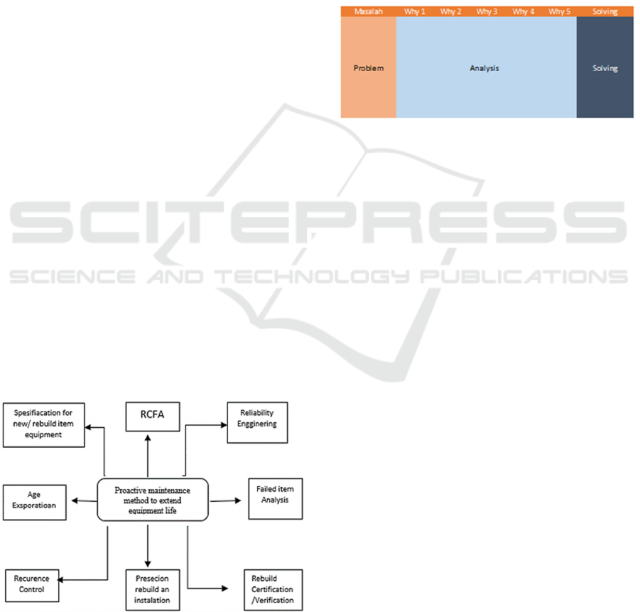
Figure 1: Proactive maintenance.
RCFA can be displayed in a variety of diagrams,
including RCA Diagrams, FTA Diagrams,
Ishikawa/Fishbone Diagrams, Flowchart Process and
Causes mapping, and 5 Why's analysis each of which
has the same perspective but differs in the focus of the
problem (Gulati, 2008).
2.3 RCPS (Root Cause Problem Solving)
Root Causes Problem Solving (RCPS) is a method
used to find the root cause of a problem in depth by
considering all the possibilities that exist and
determining the type of improvement to a problem.
Figure 2: RCPS.
2.4 EAF (Equivalent Avalability
Factor)
Equivalent Availability Factor (EAF) is an indicator
of the availability of power plants that have taken into
account the impact of generator derating. The EAF
value is a comparison obtained from the readiness of
the plant to operate divided by time.
In Indonesia, EAF is used not only as a parameter
of good or bad performance but also as a source of
revenue for the generator itself. This is because the
electricity system in Indonesia uses electricity tariffs
to PLN, assessed from two things, namely EAF
(Equivalent Availability Factor) and sales of
electrical energy. The formula for calculating EAF is:
EAF = (AH – (EUDH + EPDH + EMDH +
ESDH) / PH) x 100%
(1)
AH = PH – ( SH + RSH ) (2)
SH = FOH + MOH + POH (3)
Where:
EAF = Equivalent Availability Factor (%)
AH = Availability Hours (h)
PH = Plan Hours (h)
SH = Service Hours (h)
RSH = Reverse Shutdowh Hours (h)
EUDH = Equvalent Unplaned Derating Hours
EPDH = Equivalent Planed Derating Hours
EFDH = Equivalent Forced Derating Hours
iCAST-ES 2022 - International Conference on Applied Science and Technology on Engineering Science
758
ESDH = Equivalent Schedule Derated Hours
FOH = Forced Outage Hours (h)
MOH = Maintenace Outage Hours (h)
POH = Planed Outage Hours (h)
NMC = Net Maximum Capacity
3 RESULT
3.1 Cronology of Events
On June 15, 2020 there was a failure in the form of an
active ETS Generator, causing Unit 1 to Trip for 7
days 11 hours 01 minutes. This causes the PLTU
Anggrek to experience a lost opportunity of 179.01
MW. Based on the information obtained from the
trend data results in DCS (Distribution Control
System) and field checks, the following data were
obtained:
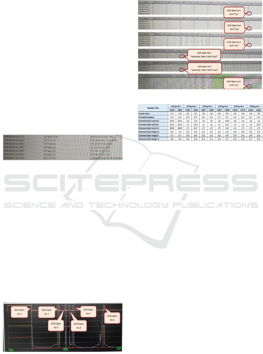
Figure 3: SOE units 1 Anggrek powerplant.
Based on the SOE table data, the following
information is obtained:
• Generator Protection Main Protection unit 1 is
active.
• ETS Trip To DCS SOE2 protection is on.
• ETS Trip To DCS SOE1 protection is on.
• ETS Trip To DCS SOE3 Protection On
• Protect ETS Protection Action
• DEH Emergency Shut-down protection is
active.
• Trip2 Boiler Shut-down Protection is active
Furthermore, the data obtained from the panel
display shows that the GCB is open during
synchronization 6 times.
Figure 4: Trend GCB opens.
Figure 5: Trend data ETS generator protection.
Figure 6: Data trend GCB opens.
In Figure 4-6, information on unit 1 data after
the Generator Trip disturbance is obtained as follows:
• The first disturbance occurred at 4:19:41,
which caused the GCB Unit 1 to Open.
• In the first fault, it can be seen that when the
ETS protection "Generator Trip" is active,
the "AVR Trip" protection generator is active
at the same time (04:19:43).
• Then the operator normalized and tried again
to sync at 5:15:41 but the sync failed, and
GCB opened again.
• Synchronous experiments were carried out
five times, but synchronous still could not be
carried out. In synchronous experiments 3 and
4, GCB unit 1 opens again with the appearance
of Generator Protection "Stator Earth Fault"
active.
3.2 FTA (Fault Tree Analysis)
There are also results from the fault tree based on
interviews with field supervisors and literature
studies:
Analysis of Causes ETS Generator Protection Failure Using Root Causes Failure Analysis and Root Causes Problem Solving Methods and
Their Effect on the EAF Value of PLTU Anggrek
759
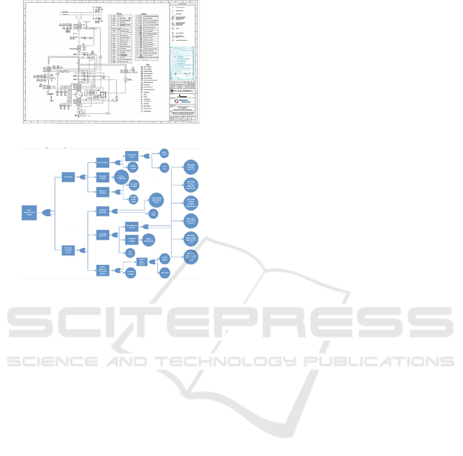
Figure 7: Generator & generator transformers protection
and metering diagram.
Figure 8: FTA (Fault Tree Analysis) of ETS generator trip.
3.3 RCFA (Root Cause Failure
Analysis)
The results of the RCFA from the chronology of
events that have been analyzed resulted in 2 main
problems, namely the failure of the AVR and the
grounding system so that there are notifications in the
form of "AVR Trip" and "Earth Stator Fault" in the
trend menu of the Generator main protection data.
1) AVR Trip
In the AVR Trip problem that appears in the 1,
2, and 3 synchronizations, there are three main root
causes that were found using the Fault tree analysis
method, including:
a) Module Failure
The module is a component of the AVR process
in the module, and there is a card that functions as an
IC or as a data processor from the field to the display.
Module failure can be affected due to damage to the
card module or IC module. This can happen because
of the indication of a short circuit on the module and
the lifetime of the module.
b) Loose Termination
A loose termination is an event where the
connecting port is loose so that the data from the field
is not conveyed to the display. This is a possible
failure of the AVR system.
c) Excitation Problem
Excitation is a process that functions to supply
direct voltage (DC) to a generator so that a generator
can produce large amounts of electrical energy. This
excitation process is actually the task of the AVR
system, which functions as a regulator of the
excitation voltage. The excitation voltage can fail
because the connection between the rotating diode
and the ports leading to the module is loose or even
disconnected. The main thing that causes the
excitation voltage problem is a damaged rotating
diode. A rotating diode is the main component of
creating direct voltage (DC) on the generator.
2) Earth Stator Fault
In the Earth Stator Fault problem that appears in
the fourth and fifth synchronization, three main root
causes were found using the Fault Tree Analysis
method, including:
a) PT10BAB02
PT10BAB02 is a potential transformer that
measures the current in the grounding system. From
the results of the chronology, there is an error in the
stator earth fault, which is also a grounding system.
What can be identified is the presence of a voltage
that penetrates the potential transformer
PT10BAB02, which should have a safety system in
the form of a surge arrester for each potential
transformer. The surge arrester in the panel is
damaged because the voltage penetrates to the stator
earth fault or grounding system. Another possibility
is the lifetime of PT10BAB02.
b) PT10BAB03
PT10BAB03 is a potential transformer that
measures the voltage on the bus side of 10.5 Kv. In
the chronology of events, there is network instability
which causes the operator to adjust the settings of the
charger tap to lower the voltage on the generator side
of the transformers. Then check the PT10BAB03
potential transformers side. An active overvoltage
alarm is seen. The value that is read on the indicator
when the alarm is active is 120.01 V. The ratio of the
potential transformer measurement is 10.5 Kv/ 100 V,
which means the actual value on the Bus has a value
of 12.001Kv. In fault tree analysis, overvoltage
conditions can be caused by a short phase to ground
or breakdown voltage on the equipment connected to
PT10BAB03. From the results of the analysis, the
first indication of damage or short on the winding
iCAST-ES 2022 - International Conference on Applied Science and Technology on Engineering Science
760
generator, winding generator transformers, and
winding auxiliary transformers. The second is
damage to the protection system in the form of a surge
arrester in several components that have a surge
arrester and are connected to PT10BAB03 because,
in the specifications, the surge arrester component is
only able to receive a voltage of 12Kv. The following
are the specifications for the surge arrester of the
PLTU Anggrek.
Table 1: Spesifications of surge arester.
Equipment
Name
Specification
Surge
Arrester
HE: 12
Ur = 12 kV
Uc= 10.2 kV
Is = 20 kA
F = 50/60 Hz
Manufacture: Tridelta Varisil
So it can be concluded that when the overvoltage
condition on the 10.5 Kv line, the surge arrester
contained in the connected component on the 10.5 Kv
line is damaged because the maximum specification
is 12Kv. The following from the analysis of the fault
tree components that were damaged include damage
to the surge arrester PT10BAB03, damage to the
surge arrester on the HV UAT (Auxilary
transformers) side, and damage to the surge arrester
on the LV UAT (Auxilary Transformers) side.
The next factor that causes overvoltage is the
termination of the system that is loose or not installed
accurately can also cause the system to be unstable.
Then the last factor is the lifetime factor of
PTBAB1003 equipment.
c) Module Generator Protection Failure
The generator failure protection module is a
module for safety when an error occurs in the
generator. In the generator protection system there are
connecting ports and modules that process data so
that if the damage is detected on the generator, the
module will send a command to the main system to
open the 10.5Kv CB. This can be a problem due to a
damaged port or a damaged module due to failure,
and a lifetime can send commands to open a 10.5 Kv
CB with a certain error, but the system is actually still
working very well. This has happened to the PLTU
Anggrek so that in the fault tree analysis, the authors
review and enter the problem into the fault tree. Next
is a loose termination. This can cause the system not
to work according to standards and can cause errors
during operation.
3.4 RCPS (Root Cause Problem
Solving)
The results of the analysis of the RCPS (Root Causes
Problem Solving), which is the selection of solution
actions based on "5 Why’s analysis" to find the right
solution according to the problems that occur.
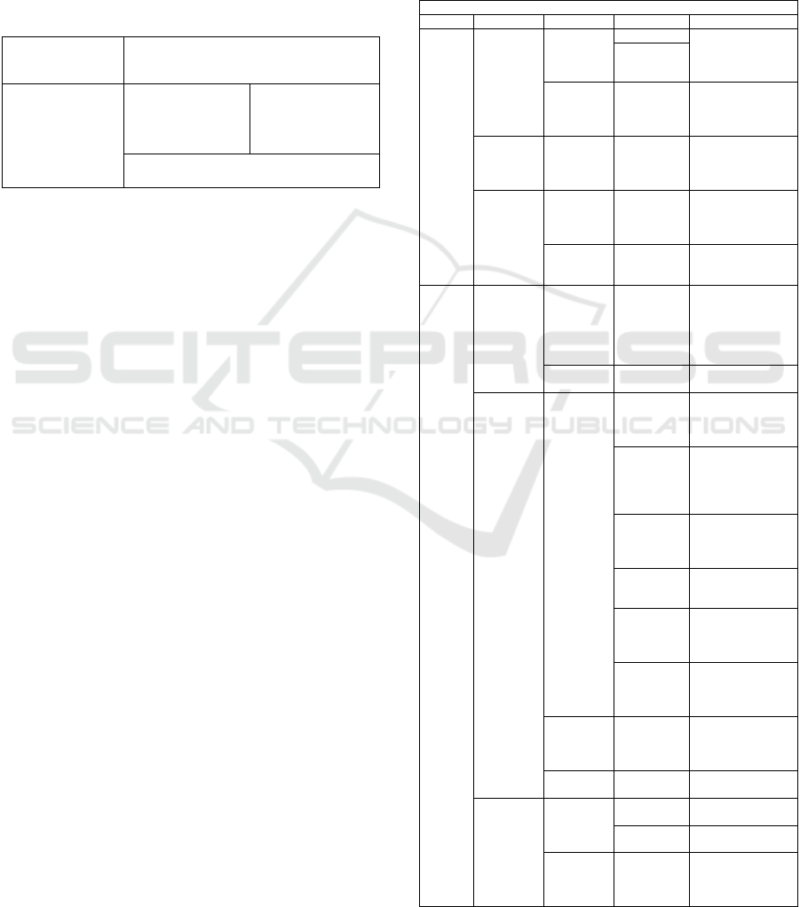
Table 2: RCPS of ETS generator trip.
Root Cause Problem Solving (RCPS)
Problem Why 1 Why 2 Why 3 Solutions
AVR
Trip
Modul
failure
Module card
is broken
Short circuit Replacing the
damaged card
module with a new
card module
Life time
Modul
Corupt
Repair the module if
it can still be used by
checking
com
p
onents
Loose
Termination
Thightening
Factor
Checking or
repairing
connections between
p
orts on the AVR
Problem
Excitation
Loose
Termination
Check and repair
between ports on
connection and
excitation s
y
stem
Rotating
Diode is
b
roken
Replacement of
rotating diode
com
p
onents
Stator
Earth
Fault
VT Panel
10BAB02
The surge
arrester
inside the
panel is
broken
Check the surge
arrester with the IR
test, if the results
show no voltage
then the surge
arrester is re
p
laced
life time
Change of VT Panel
10BAB02
VT Panel
10BAB03
Short Phase
to ground
Generator
winding
damage
Replacing the
damaged component
of the winding
g
enerator
Transformers
winding
generator
damage
Replacing the
damaged
components of the
winding Generator
transformers
Damage to
winding
auxiliary
transformers
Replacing the
damaged Auxillary
Transformers
windin
g
com
p
onents
Damage to
surge arrester
PT 10BAB03
Replacing a faulty
surge arrester
Damage to
the surge
arrester on
the HV UAT
Replacing a faulty
surge arrester
Damage to
surge arrester
on LV side of
UAT
Replacing a faulty
surge arrester
Loose
termination
Thightening
factor
Checking and
reconnecting ports
and loose
connections
life time
Change of VT Panel
10BAB03
Modul
Generator
Protection
failure
Port IO
circuit
Modul failure
Replace the failed
module
life time
change port or
connection
Loose
termination
Checking and
reconnecting ports
and loose
connections
Analysis of Causes ETS Generator Protection Failure Using Root Causes Failure Analysis and Root Causes Problem Solving Methods and
Their Effect on the EAF Value of PLTU Anggrek
761
3.5 EAF (Equivalent Avalability
Factor)
From the results of interviews and discussions with
field supervisors, PLTU Anggrek has a work contract
with PLN where the contract discusses the regulations
for taking shutdown hours, where the shutdown hours
are calculated daily. So in planning improvements by
conducting RCFA first, it takes 4 days to work (based
on interviews with field supervisors). Whereas before
doing RCFA, it takes 7 days to work.
Table 3: Comparison of SH anggrek powerplant unit 1 June
2020.
Comparison of shutdown hours of PLTU Anggrek
in June 2020
No Problem
Before doing
RCFA (h)
After doing
RCFA (h)
1
ETS
Generator Trip
179.02 96
2
Low Vaccum
Condense
r
2.6 2.6
Total 181.62 98.6
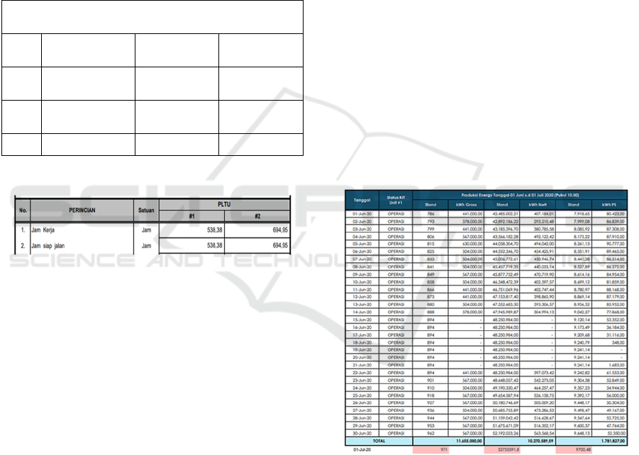
a) Calculating June EAF before doing RCFA
Figure 9: Data for AH Anggrek powerplant for June 2020.
It is known in Figure 14 that the working hours
of PLTU Anggrek Unit 1 in June are 538.38 hours,
so :
EAF = (AH – (EUDH + EPDH + EMDH +
ESDH) / PH) x 100%
EAF = ((538.38 -(0))/720)X 100%
EAF = 74.78% (4)
b) Calculating June EAF after doing RCFA
From table 4, the value of SH (Shutdown Hours)
of Anggrek Powerplant during June 2020 is 98.8
hours. The AH (Availability Hours) value is
calculated using the formula:
AH = PH-(SH+RSH )
= 720-(98.8+0 )
= 621.2 (5)
Then the EAF value is:
EAF = (AH – (EUDH + EPDH + EMDH +
ESDH) / PH) x 100%
EAF=((621.2 -(0))/720)X 100%
EAF = 86.62% (6)
From the results of the EAF value of the Anggrek
Powerplant in June 2020 which has been calculated,
the value before doing RCFA on the ETS Generator
trip problem is 74.78%, while after doing RCFA the
value is 86.28%. Compiling a repair plan using RCFA
can increase the EAF value by 12.1%. The EAF value
after carrying out the RCFA exceeds the EAF value
set by PJB as a work contact to the PLTU Anggrek,
which must be above 82.72% for semester 1 (January-
June), while for semester 2 (July-August), it must
have a value above 71.5%.
3.6 Cost Benefit Analysis
After analyzing the EAF value, it is necessary to
calculate how much profit is obtained when
conducting RCFA analysis after the ETS Generator
Trip event. The following is the electricity production
data for unit 1 PLTU Anggrek in the month of june
2020:
Figure 10: Electricity production unit 1 PLTU Anggrek in
June 2020.
From the figure, the value of electricity
production per day by PLTU Anggrek is obtained,
which is distributed to 150 KV substations. Before
doing the RCFA analysis, it is worth 10,270,598.59
Kwh. Meanwhile, the average daily production of
PLTU Anggrek is 446,547.76 Kwh. Then the
Powerplant income is calculated before conducting
the RCFA:
iCAST-ES 2022 - International Conference on Applied Science and Technology on Engineering Science
762

Price of electricity/Kwh: Rp. 1,444.70
1 month income = 10,270,598.59 x 1,444.70
= Rp. 14,837,933,800 (7)
Meanwhile, the revenue for the PLTU Anggrek
after RCFA is:
Average daily electricity production = 446,547.76
Kwh
Total production for 1 month = 10,270,598.59 +
(446,547.76 x 3)
=11.610.241.9 Kwh (8)
Price of electricity/Kwh = Rp. 1.444,70
1 month income = 11.610.241,9 x 1.444.70
=Rp. 16.773.316.500 (9)
From the cost-benefit analysis, it is found that
doing RCFA will increase generator income by Rp.
1,935,382,700.
4 CONCLUSIONS
1) In calculating PLTU Anggrek could not reach
the target set by PJB, namely EAF in semester 1
(January-June) of 82.72%, but when have done
RCFA, the EAF value has increased by 12.1% so that
it is worth 86.28% and has reached the target set by
PJB.
2) From the income calculation, it was found that
doing RCFA at the ETS Generator Trip event was
able to increase revenue by Rp. 1,935,382,700.
REFERENCES
Zavagnin, R. (2008). An overview of a Root Cause Failure
Analysis (RCFA) process. Paper presented at the Banff,
Canada: IPEIA Conference.
Dono, M. W. (2017). Implementasi Reliability Centered
Maintenance (RCM) II Pada Boiler B-1102 Di Pabrik I
PT. PETROKIMIA GRESIK (Doctoral dissertation,
Institut Teknologi Sepuluh Nopember).
Pambudi, A. (2004). Analisa Kerusakan Regulator A1 AVR
Diesel Generator Pada Kapal Patroli Tipe KCR (Kapal
Cepat Rudal) (Doctoral dissertation, Institut Teknologi
Sepuluh Nopember).
Reimert, D. 2006. Protective Relaying for Generation
System. England: CRC Press.
Trisya Wulandari. 2011. Analisa Kegagalan Sistem dengan
Fault Tree. Depok: Tugas Akhir Universitas Indonesia.
Amalia, Z. (2016). Perancangan Sistem Pemeliharaan Pada
Turbin 103-Jt Mengggunakan Metode Reliability
Centered Maintenance (Rcm) (Studi Kasus: Pt.
Petrokimia Gresik Unik Amonia Pabrik I) (Doctoral
dissertation, Institut Teknologi Sepuluh Nopember
Surabaya).
Wisudana, D. H. (2015). Evaluasi Reliability dengan
Metode Kuantitatif dan Kualitatif RCFA pada Unit
Superheater, Desuperheater dan Exhaust Damper
HRSG 3.1 di PT. PJB UP. Gresik (Doctoral
dissertation, Institut Teknologi Sepuluh Nopember).
Gulati, Ramesh., 2008. Maintenance & Reliability Best
Practice Handbook. New York: Industrial Press. Inc,
2008.
Sukendar, I., Syahkroni, A., & Prasetyo, B. T. (2019).
ANALISA Kebocoran Pada Body Mill/Pulverizer
Menggunakan Metoda Root Cause Failure Analysis
(RCFA). Applied Industrial Engineering Journal, 3(2),
12-21.
Analysis of Causes ETS Generator Protection Failure Using Root Causes Failure Analysis and Root Causes Problem Solving Methods and
Their Effect on the EAF Value of PLTU Anggrek
763
