
Nutrient Feeding Automation System in Hydroponic Cultivation
Using NodeMCU Based on PID Controller
Nurmahaludin Nurmahaludin
1
and Gunawan Cahyono
2
1
Politeknik Negeri Banjarmasin, Jl. Brig Jend. Hasan Basri, Banjarmasin, Indonesia
2
Universitas Lambung Mangkurat, Jl. Brigjen Jalan Hasan Basri, Indonesia
Keywords: Hydroponic, NodeMCU, PID Controller.
Abstract: Hydroponic system is the cultivation of plants without soil and using only nutrient solutions in water. The
concentration of these nutrients needs to be adjusted before being given to plants. If the nutrients given are
too concentrated, the plants will die or wilt, on the contrary if the concentration is low, the plants will lack
nutrients. The automation system for regulating nutrient concentrations in this study is based on a PID
controller using nodeMCU. The setpoint is the reference nutrient concentration value which is compared with
the current concentration output measured by the sensor to get an error. If the error is positive, it indicates that
the plant is on the verge of nutrient deficiency so that the nutrient solution valve needs to be opened to increase
the concentration of the solution. On the other hand, if the error is negative it means that the concentration of
the solution exceeds the value it should have, so the water valve needs to be opened to reduce the concentration
that occurs. The test results show that the PID controller with Kp=0.8, Ki=0.5, and Kd=0.5 gives a fairly good
response and a relatively smaller average error of 3.92.
1 INTRODUCTION
There are number of studies have been carried out in
relation with control hydroponic plants, including the
design of a hydroponic plant automation system
through regulating temperature and humidity,
electrical conductivity, pH, and lighting using sensors
and microcontrollers (Pache, Dudhe, & Dharaskar,
2022) as well as temperature and level regulation
(Azhari, Simanjuntak, Hakim, & Sabar, 2022)
(Chaiwongsai, 2019).
Control algorithms are used in the regulation of
hydroponic plants to obtain better performance,
including which uses the PID method to adjust pH of
solution (Hadiatna, Dzulfahmi, & Nataliana, 2020).
Another control method is Fuzzy Logic Controller to
adjust nutrient concentration (Nurmahaludin,
Cahyono, & Riadi, 2020) and to regulate the electrical
conductivity and pH of hydroponic plants (Dela
Vega, Gonzaga, & Gan Lim, 2021).
The next development is the regulation of
providing nutrition to hydroponic plants wirelessly
where Arduino is connected to Wi-Fi (Tembe, Khan,
& Acharekar, 2018) (Sihombing, Karina, Tarigan, &
Syarif, 2018) and an Ethernet module by connecting
to a microcontroller (Haq, Suwardiyanto, & Raya
Jember, 2018). Even though the control has been
done remotely, the settings are still done on-off where
the microcontroller will turn on or turn off the
actuator (pumping machine) when the control
objective has been achieved.
In this study, the PID control algorithm is used
where the resulting error will be processed
proportional, integral, and derivative. The valve
opening process depends on the servo motor
movement based on the PID controller output value
so that the desired density is achieved faster than the
on-off method. The control process is carried out
wirelessly using NodeMCU via an android device.
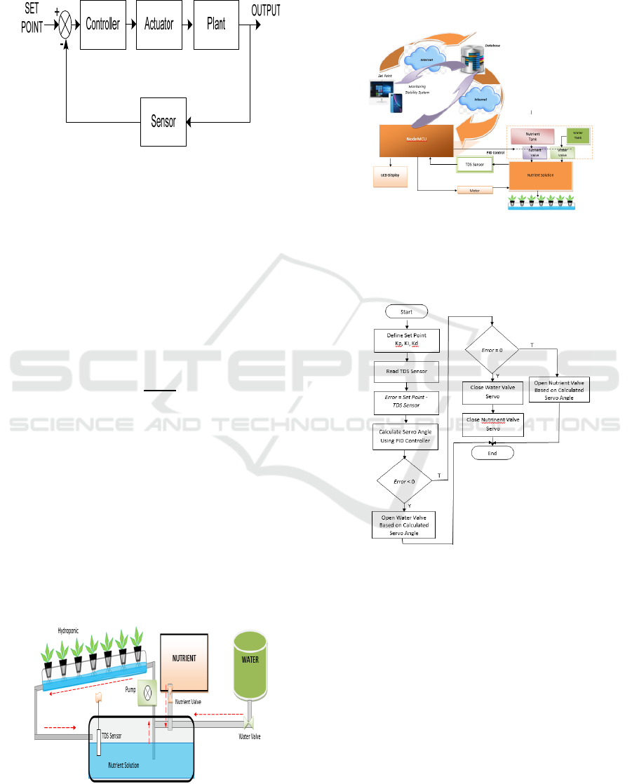
The control process is basically an attempt to keep
output (response) at the desired value of one or more
variables. Control system also aims to obtain good
performance from the controlled variables. Closed
loop control block diagram is shown in Figure 1.
Plant is a controlled system in this case is the
concentration of the hydroponic solution.
Process begins by giving a set point in the form of
the desired nutrient concentration value, then
measure the current output using the TDS sensor. The
results obtained are compared with the set point to
find errors that occur.
Nurmahaludin, N. and Cahyono, G.
Nutrient Feeding Automation System in Hydroponic Cultivation Using NodeMCU Based on PID Controller.
DOI: 10.5220/0011862100003575
In Proceedings of the 5th International Conference on Applied Science and Technology on Engineering Science (iCAST-ES 2022), pages 669-673
ISBN: 978-989-758-619-4; ISSN: 2975-8246
Copyright © 2023 by SCITEPRESS – Science and Technology Publications, Lda. Under CC license (CC BY-NC-ND 4.0)
669
e(t) = SP
–
PV (1)
where e(t) is error at time t, SP is set point, and PV is
present sensor's measured output.
Figure 1: Block diagram of closed loop control system.
Controller will provide an action based on the
control algorithm used. If using a PID controller, the
resulting error will be processed proportionally (P),
integral (I), and derivative (D) as follows:
a. Proportional Controller (P):
𝑃=𝐾
𝑒(𝑡)
(2)
b. Integral Controller (I):
𝐼= 𝐾
𝑒(𝑡)
(3)
c. Derivative Controller (D):
𝐷= 𝐾
𝜕𝑒
(
𝑡
)
𝜕𝑡
(4)
2 METHODS
The design of the nutrient concentration control
system in order to obtain the nutrient concentration in
accordance with the reference value for each type of
hydroponic plant is shown in Figure 2. To adjust the
solution concentration, a PID control algorithm is
used which will adjust the servo openings in the
nutrient and water valve. After the concentration of
the solution required by the plant is reached, the
hydroponic plants are watered.
Figure 2: System design for nutrient concentration control.
2.1 System Design
Figure 3 shows the hardware design and online
network. The main controller in system is the
NodeMCU microcontroller based on the ESP8266
module.
Figure 3: Hardware and network design.
The process of adjusting the concentration of the
nutrient solution is shown in the flow chart as shown in
Figure 4.
Figure 4: Control process flowchart.
2.2 Schematic Circuit
The schematic of electronic circuit is shown in Figure
5. Schematic has the following pin out configuration:
1. The TDS sensor will be connected to the analog pin
A0 of the NodeMCU microcontroller. The sensor
probe is placed in a tub of nutrient solution that
flows into the hydroponic NFT.
2. RTC and LCD use serial I2C, each of which for
SDA data is connected to the D1 pin of the
NodeMCU Microcontroller. Meanwhile, the SCL
leg is connected to the D2 pin of the NodeMCU
Microcontroller.
iCAST-ES 2022 - International Conference on Applied Science and Technology on Engineering Science
670
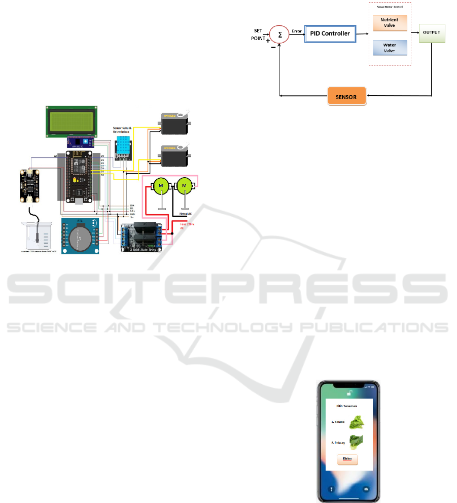
3. Temperature and humidity sensors are connected
to the D0 pin of the NodeMCU microcontroller
4. Solid State Relay to drive the stirrer motor in the
NFT nutrient circulation basin and the main
nutrient solution reservoir A and B, gets a trigger
from pins D3 and D4 of the NodeMCU
microcontroller.
5. Servo motor is used to rotate the water valve and
the main nutrient valve solution A and B
connected to the D5 and D6 pins of the NodeMCU
microcontroller.
Figure 5: Electronic circuit schematic.
2.3 PID Control Algorithm Design
The nutrient solution concentration control system
with PID control as shown in Figure 6 is as follows:
1. The system input (set point) is the desired reference
value, in this case the concentration value of the
hydroponic plant nutrient solution.
2. The system output is the current value of the
nutrient solution concentration measured using
the TDS (Total Dissolved Solids) sensor.
3. The output value is then compared with the set
point to calculate the error.
4. The output of the PID controller will adjust the
angle of the servo motor to open the nutrient
solution or water valve.
5. If the error value is positive, it indicates that the
plant is approaching the threshold of excess
nutrients. So the controller will drive the servo
motor to open the water valve.
6. On the contrary, if the error value is negative, it
indicates that the plant is starting to approach the
threshold of nutrient deficiency so that the
nutrient solution valve needs to be opened through
servo motor movement.
7. System response data (output) is sent to the
database via the internet by the microcontroller.
These responses can be accessed and displayed
via the web for monitoring and analysis of system
transient responses.
Figure 6: Nutrient concentration control system block
diagram.
3 RESULT AND DISCUSSION
Node-MCU microcontroller will retrieve data from
the database in the form of a reference value for the
concentration of the desired plant nutrient solution.
3.1 Determine Set Point
The data is a set point that can be selected online via
a gadget or computer based on the type of plant.
Display of plant type selection as shown in Figure 7.
In Figure 7 there are two types of plants to be selected.
The selection is based on the type of hydroponic
plants. For example lettuce will be selected then after
the submit button is clicked, the nutrient density value
data from the database will be sent to the NodeMCU
as a set point is an error that will be processed by the
microcontroller using the PID controller.
Figure 7: Web based hydroponic plant selection display.
The mechanism for using web based program is
as follows:
1. Activate the WiFi access point that will connect to
NodeMCU microcontroller.
2. Turn on the hardware device for the nutrition
system for hydroponic plants.
Nutrient Feeding Automation System in Hydroponic Cultivation Using NodeMCU Based on PID Controller
671
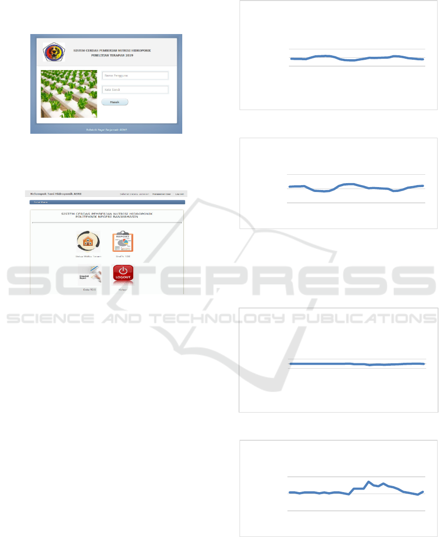
3. After a few moments, setpoint value, TDS sensor,
temperature, humidity and time display will
appear on the LCD.
4. Open the internet web address and then enter the
username and password as shown in Figure 8.
Figure 8: Menu login.
5. Selecting planting time setup menu as shown in
Figure 9.
Figure 9: Main menu display.
6. Determination of set point starts from the setup
menu for planting date and time on the website.
7. Return to the main menu to enter the TDS Data
menu, to display TDS data, temperature and
humidity. Set point value will be sent to the
NodeMCU microcontroller via the internet as
shown in Figure 7 as before.
8. TDS Graph menu provides system response in
reaching a predetermined set point.
3.2 PID Controller Simulation Results
PID controller testing aims to determine the effect of
the values of Kp, Ki, and Kd on the system response
and the resulting error. Figure 10 provides test results
with values of Kp=0.8, Ki=0.3, and Kd=0.2, where
the value of the concentration of the solution from the
TDS sensor readings are taken for each sampling
time.
Response of the system to the set point is shown
in Figure 5.13, with a set point value of 600 ppm.
While the resulting error which is the difference
between the set point and the output is given in Figure
11. The average error value of the test is 6.95.
Figure 10: System response for Kp=0.8, Ki=0.3, Kd=0.2.
Figure 11: System error for Kp=0.8, Ki=0.3, and Kd=0.2.
Figure 12 is the result of testing using a PID
controller with Kp=0.8, Ki=0.5, Kd=0.5 and a set
point of 600 ppm. Average error value of the test is
3.92 as shown in figure 13.
Figure 12: System response for Kp=0.8, Ki=0.5, Kd=0.5.
Figure 13: System error for Kp=0.8, Ki=0.5, and Kd=0.5.
Based on the simulation results, the PID controller
values with Kp=0.8, Ki=0.5, and Kd=0.5 gave a
550
600
650
1 3 5 7 9 111315171921232527
i
lai Kekentalan
Waktu ke-
Respon Sistem Terhadap Set
Point
-50
0
50
1 3 5 7 9 11 131517 192123 2527
Nilai Error
Data ke-
Grafik Error Respon Sistem
550
600
650
1 3 5 7 9 1113 15 1719 212325 27
a
i Kekentalan
Waktu ke-
Respon Sistem Terhadap Set
Point
-20
0
20
1 3 5 7 9 111315171921232527
Nilai Error
Data ke-
Grafik Error Respon Sistem
iCAST-ES 2022 - International Conference on Applied Science and Technology on Engineering Science
672

smaller average error and a better response. This is
because integral controller will reduce the steady state
error and the derivative controller is useful for
reducing the overshoot that occurs. So that by
increasing the values of Ki and Kd compared to the
initial value will give better results.
4 CONCLUSIONS
Control the concentration of nutrient solution for
hydroponic plants using a PID controller where the
output of the controller will regulate the opening of
servo motor in the nutrient and water tank valve.
The test results show that the PID controller with
Kp = 0.8, Ki = 0.5, and Kd = 0.5 gives a fairly good
response and a relatively smaller average error of
3.92.
Improvement of system response and mean error
in this test is done by increasing the constant of
integral controller (Ki) and derivative controller (Kd).
ACKNOWLEDGEMENTS
Many thanks to the Politeknik Negeri Banjarmasin
for providing funding so that this research can be
completed.
REFERENCES
Azhari, Simanjuntak, D., Hakim, L., & Sabar. (2022).
Design and control system of temperature and water
level in hydroponic plants. Journal of Physics:
Conference Series, 2193(1). https://doi.org/10.1088/
1742-6596/2193/1/012018
Chaiwongsai, J. (2019). Automatic control and
management system for tropical hydroponic
cultivation. Proceedings - IEEE International
Symposium on Circuits and Systems, 2019-May, 1–4.
https://doi.org/10.1109/ISCAS.2019.8702572
Dela Vega, J. A., Gonzaga, J. A., & Gan Lim, L. A. (2021).
Fuzzy-based automated nutrient solution control for a
hydroponic tower system. IOP Conference Series:
Materials Science and Engineering, 1109(1), 012064.
https://doi.org/10.1088/1757-899x/1109/1/012064
Hadiatna, F., Dzulfahmi, A., & Nataliana, D. (2020).
Analisis Penerapan Kendali Otomatis berbasis PID
terhadap pH Larutan. ELKOMIKA: Jurnal Teknik
Energi Elektrik, Teknik Telekomunikasi, & Teknik
Elektronika, 8(1), 163. https://doi.org/10.26760/
elkomika.v8i1.163
Haq, E. S., Suwardiyanto, D., & Raya Jember, J. (2018).
Online Farm Menggunakan Greenhouse Untuk
Tanaman Hidroponik Berbasis Web. Jurnal Ilmiah
NERO, 3(3), 193–200.
Nurmahaludin, Cahyono, G. R., & Riadi, J. (2020). Nutrient
concentration control system in hydroponic plants
based on fuzzy logic. 3rd International Conference on
Applied Science and Technology, ICAST 2020, 141–
146. https://doi.org/10.1109/
iCAST51016.2020.9557617
Pache, A., Dudhe, A., & Dharaskar, B. (2022). Automated
Hydroponics Systems, A Review and Improvement.
11(5), 19–25. https://doi.org/10.21275/
SR22429121630
Sihombing, P., Karina, N. A., Tarigan, J. T., & Syarif, M.
I. (2018). Automated hydroponics nutrition plants
systems using arduino uno microcontroller based on
android. Journal of Physics: Conference Series, 978(1).
https://doi.org/10.1088/1742-6596/978/1/012014
Tembe, S., Khan, S., & Acharekar, R. (2018). IoT based
Automated Hydroponics System. 67–71.
Nutrient Feeding Automation System in Hydroponic Cultivation Using NodeMCU Based on PID Controller
673
