
Planned Helical Rack Gear Transmission for Slider Driven by
Y-Axis Cremona Construction Frame on 3-Dimensional Concrete
Printing Machine
Iwan Gunawan
a
, Nandang Rusmana
b
and Heri Setiawan
c
Manufacturing Engineering Department, Bandung Polytechnic of Manufacturing,
Jl. Kanayakan No. 21 – Dago, Bandung, Indonesia
Keywords: 3D Printing, Accuracy, Acceleration, Power, Transmission Elements, Helical Rack & Pinion Gear.
Abstract: 3D concrete printing (3DCP) is an innovative method of 3 Dimensional concrete cast printer in the civil
building construction industry that can optimize process time &cost, design flexibility, and reduce errors and
is environmentally friendly. This 3D printing machine is of the cartesian type there are 3 frames as the
direction of movement, namely the X, Y, and Z axes. Construction of the Y-axis frame acts as a load support
for the X- and Z-axis frames and as the foundation of the X - Z axis frame drive slider in the Y-axis frame. This
Y-axis frame is the base of the overall construction of the machine. 3D printing technology (3D Printing)
plays a fundamentally important role in the printing process. To satisfy these demands, preparations are being
made for the choice of the Helical Rack & Pinion Gear transmission component, which will be used as a Y-
axis slider driver for 3D printers for civil structures. After doing the investigation, it was discovered that a Y-
axis slider driver for 3D printers (3D Printing) for civil buildings may be made using a Helical Rack & Pinion
Gear transmission element with the following specifications: 1.25 module and 20° helix angle.
1 INTRODUCTION
A 3D printing machine for civil buildings is one of
the projects that this year's Manufacturing
Technology study program participants will create.
The transmission element plays a crucial part in the
molding process since it affects things like precision,
acceleration, and load-bearing strength. In order to
fulfill these requirements, planning is done for the
selection of the appropriate transmission element to
be used as a Y-axis slider driver for 3D printers for
civil buildings.
Planning the transmission of helical rack and
pinion gear is important because it has a direct effect
on the movement of the 3D concrete printing machine
that will be made. These factors include accuracy,
convenience in the control system, and the strength to
withstand the load on the Y-axis slider. What is
interesting here is that there is a discussion about the
method of aligning the connection between the rack
a
https://orcid.org/0000-0001-9791-0710
b
https://orcid.org/0000-0001-8772-5626
c
https://orcid.org/0000-0001-8767-1429
gears, which is very vital for the continuity of the
movement of the relationship between the helical rack
and helical pinion gear.
The plan is to select what transmission elements
are suitable for use on the 3D printing machine, which
will be made based on predetermined criteria.
Thus, the purpose of this study is to serve as a
form of planning for applying helical rack and pinion
gear transmission elements in 3D concrete printing
machines.
2 METHODOLOGY
The stages of the research were as follows:
a. Knowing the fundamentals of planning the
selection of transmission elements for the Y axis
slider drive
b. Recognizing issues with the transmission element
for the Y axis slider drive
608
Gunawan, I., Rusmana, N. and Setiawan, H.
Planned Helical Rack Gear Transmission for Slider Driven by Y-Axis Cremona Construction Frame on 3-Dimensional Concrete Printing Machine.
DOI: 10.5220/0011845900003575
In Proceedings of the 5th International Conference on Applied Science and Technology on Engineering Science (iCAST-ES 2022), pages 608-613
ISBN: 978-989-758-619-4; ISSN: 2975-8246
Copyright © 2023 by SCITEPRESS – Science and Technology Publications, Lda. Under CC license (CC BY-NC-ND 4.0)
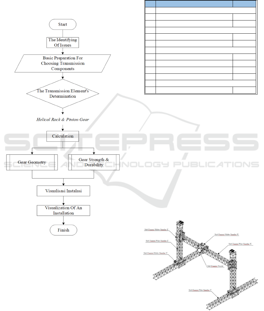
c. Review and choose the appropriate transmission
element to use as a Y-axis slider drive
d. Perform calculations on the geometry and
strength of the gear that will be used as a
transmission element for the Y-axis slider drive
e. Visualize the installation of the Helical Rack &
Pinion Gear transmission element as a Y-axis
slider drive.
Figure 1: Flowchart for Y-Axis Slider Transmission
Element Selection.
3 FINDINGS AND DISCUSSION
3.1 Needs
At this stage, identification of the needs for the Y-axis
slider driving transmission element is carried out on
the 3-dimensional (3-D printing) building casting
machine that will be made. The determination of this
need is based on the results of the discussions
between MEC 2019 students and the head of the
Manufacturing Technology study program.
Therefore, a list of demands is made in
Figure
2 below,
which one D is Demand and W is Wishes.
Figure 2: Demand List for Transmission Elements for Y-
Axis Slider Drive.
3.2 Basic Preparation for Choosing
Transmission Components
Planning the selection of transmission components
for the Y-axis slider drive is based on Knowing the
load received, the functional style, The installation
place are all examples of knowledge.
Figure 2 above is a design of the construction of a
3-dimensional (3-D) concrete printing building
casting machine that will be made. This design has
gone through several rounds of consideration, which
ultimately adhere to the principle of simplicity by
prioritizing functions that are expected to run
properly and correctly.
Figure 3: 3D printing machine construction design for civil
buildings.
No. Demands Priority
1 Making
Is possible in the Polman workshop. W
Utilizes numerous common parts D
2 Assembly
Disassemble-Install D
Simple Assembly Method W
3 Maintenance
Easy Maintenance D
Easy Fix D
Low Maintenance and Repair Cost W
Easy to clean W
4 Marketing
Needed for Civil Development D
Planned Helical Rack Gear Transmission for Slider Driven by Y-Axis Cremona Construction Frame on 3-Dimensional Concrete Printing
Machine
609
The load that was applied to the Y-axis slider is
broken out in Figure 4
Figure 4: Specifics of the Load that Y. Axis Slider.
The Y-axis slider drive transmission element must
be capable of moving a load weighing 640 kg, as
shown in
Figure
4 above.
3.3 Alternative Selection for the
Transmission Element
Planning for the selection of transmission elements is
based on observations made on existing 3D printing
machines made in Russia and then evaluated
(additions and subtractions).
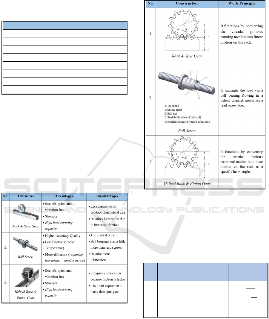
Figure 5: Explains the construction and operation of the
transmission element.
Figure 5
is provided below so that you can learn
more about the design and operation of different
transmission elements that can be employe
The benefits and drawbacks of each potential Y-
axis slider transmission element are listed in
Figure 6
Figure 6: Lists the advantages and disadvantages of
substitute transmission components.
3.4 Helical Rack and Pinion Gear
Calculation
Calculation of Helical Gear and Helical Rack ,there are
Torque T= (F
u
d
w
)/2000 = 0.024 kgfm=0.235 NM and
Tangential Speed V = d
w
n/19100 = 5.187 m/s
Figure 7: Calculation of Helical Gear and Helical Rack
Strength and Durability.
The geometry calculations for the Helical Rack
and Helical Gear that will be used on the Y-axis slider
are shown in Figure 8.
No Component Weight Amount Total Weight
1. X-Axis Pillar 115 Kg 1 115 Kg
2. Z-Axis Pillar 80 Kg 2 160 Kg
3. X-Axis Slider 70 Kg 1 70 Kg
4. Z-Axis Slider 70 Kg 2 140 Kg
5. Nozzle 30 Kg 1 30 Kg
6. Motor 2 Kg 5 10 Kg
7. Weight Balancer 57,5 Kg 2 115 Kg
Amount 640 Kg
Types
of
Gear
Tangential Force,
F
u
Axial Force, F
a
Radial Force, F
r
Helical
Gear
𝐹𝑢 =
1.95𝑥10
5
𝑃
𝑑
𝑤
𝑛
=
1.95𝑥10
5
0.75
𝑑
𝑤
3000
= 1.475 𝑘𝑔𝑓
= 14.464 𝑁𝑚
𝐹𝑢 tan 𝛽
=
1.475
0.363
= 0.535 𝑘𝑔𝑓
= 5.246 𝑁𝑚
𝐹𝑢
tan 𝛼
𝑛
cos 𝛽
= (1.475)
0.363
0.939
= 0.570 𝑘𝑔𝑓
= 5.589 𝑁𝑚
iCAST-ES 2022 - International Conference on Applied Science and Technology on Engineering Science
610
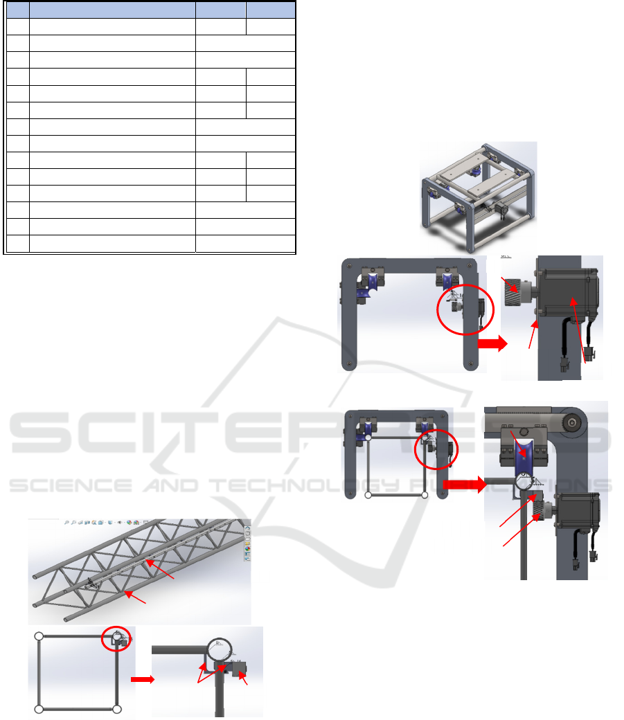
Figure 8: Geometric Calculations for Helical Gear and
Helical Rack.
The findings of the strength and durability
calculations for the Helical Rack and Helical Gear
that will be used on the Y-axis slider are shown in
Table 6. If known: P = 0.75 kW (Panasonic AC Servo
Motor 750 W), N = 3000 rpm (Panasonic AC Servo
Motor 750 W) and D
w
= 33,030 mm
3.5 Installation of Helical Rack and
Pinion Gear
3.5.1 Installation of Helical Rack on Y-Axis
Pillar
Figure 9: Installation Of Helical Rack on Y-Axis Pillar.
The installation of helical rack gear on the Y-axis
pillar using by electric welding, whith two rack gear
brackets are attached to the Y-axis pillar.
3.5.2 Installation Helical Pinion Gear on Y
Axis Slider
The helical pinion gear installation on the Y-axis
slider is shown in the visualization above. The servo
motor is mounted to a plate that serves as a motor
bracket on the Y-axis slider, and the motor is coupled
with the shaft of the helical pinion gear.
Figure 10: Helical Pinion Gear Installation on Y Axis
Slider.
3.5.3 Installation of Helical Rack & Pinion
Gear on Y-Axis Slider Transmission
The installation of Helical Rack & Pinion Gear on a
Y-axis slider is shown in the visualization above.
Using electric welding, two rack gear brackets are
attached to the Y-axis pillars. The servo motor is
mounted to a plate that serves as a motor bracket on
the Y axis slider, and the motor is coupled with the
shaft of the helical pinion gear
No. Item Gear Rack
1. Normal Module (m
n
) 1.25 1.25
2. Normal Pressure Angle (α
n
) 20°
3. Helix Angle (β) 20°
4. N. of Teeth & Helical Hand (z) 25 (L) 336 (R)
5. Normal Coefficient of Profil Shift (x
n
) 0 -
6. Pitch Line Height (H) - 26.17
7. Radial Pressure Angle (α
t
) 21.106°
8. Mounting Distance (a
x
) 42.81
9. Pitch Diameter (d) 33.280 -
10. Base Diameter (d
b)
31.016 -
11. Addendum (h
a
) 1.25 1.25
12. Whole Depth (h) 2.812
13. Outside Diameter (d
a
) 35.78
14. Root Diameter (d
f
) 30.156
Helical Rack
Y Axis Pilla
r
Bracket
R
ack
Rack
Gea
U-Wheel
R
ack
Pinion Gea
r
Bracket
Motor
Moto
r
Pinion
Planned Helical Rack Gear Transmission for Slider Driven by Y-Axis Cremona Construction Frame on 3-Dimensional Concrete Printing
Machine
611
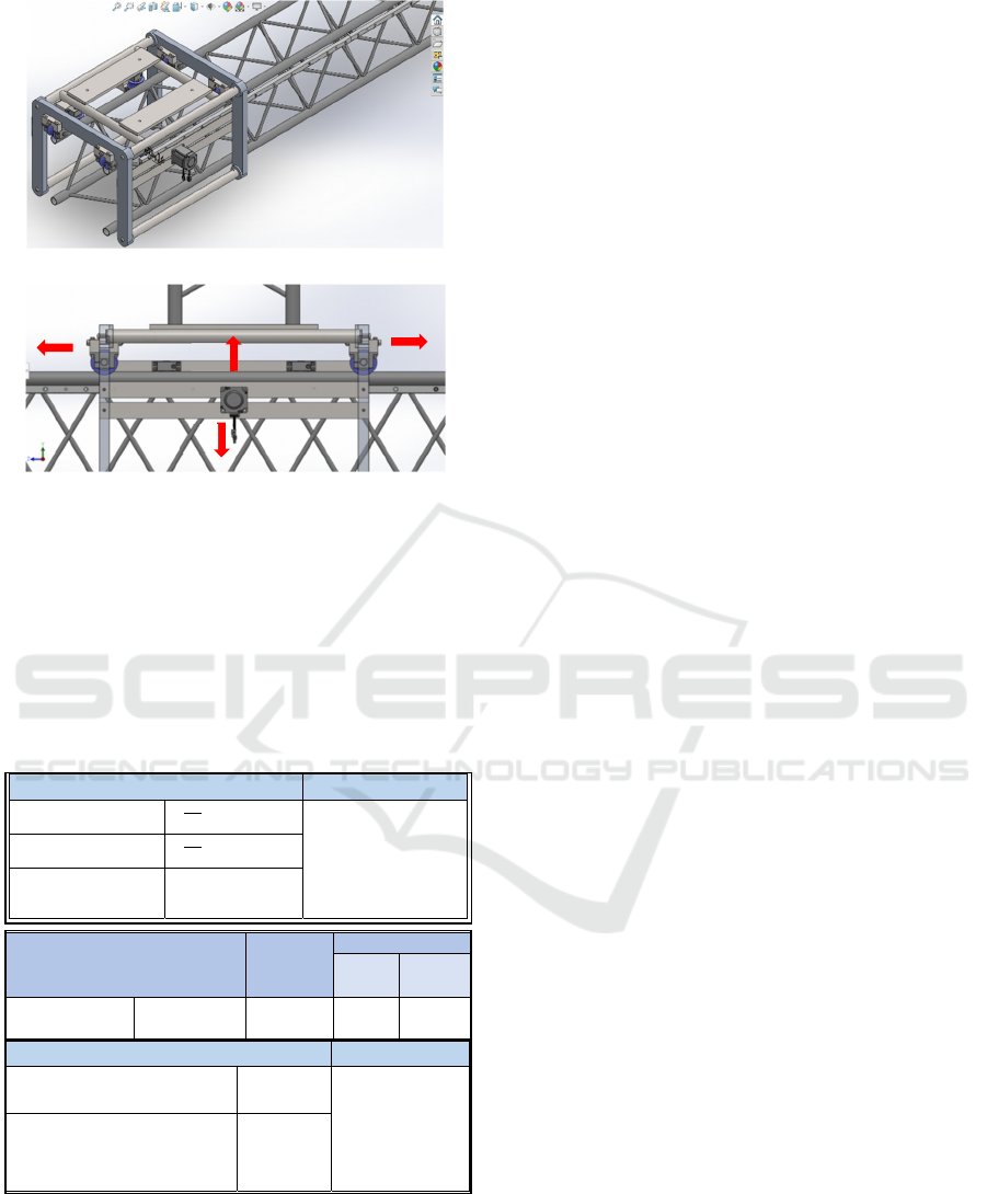
Figure 11: Helical Rack & Pinion Gear Installation on Y-
Axis Slider Transmission.
The U profile wheel (U-Wheel) serves as a
counterbalance to the servo motor on the other side
on the Y-axis slider. The U-Wheel also aids in
preventing the slider from tipping over on one side,
which would be heavier given the existence of a servo
motor in that situation.
The force exerted on the wheel can therefore be
calculated as follows:
Figure 12: Teflon Material's Frictional Coefficient with
Iron.
On the basis of Figure 12 above, it is presumed
that the Y-axis slider travels to the right as a result of
the motor's force. The friction force between the Y-
axis pillar and the U-Wheel is thus seen as follows:
According to the calculations above, the motor
must exert a force that is more than 98 N. Because the
Y axis slider won't move if the motor's force is less
than 98 N. If condition of The U-Wheel under normal
force, It is presumed that the load is split across the
two sliders because there are two sliders on the Y
axis. It is expected that the load is distributed equally
among the four U-shaped wheels on one slider, which
operate on the pillars.
4 CONCLUSIONS
In general, the following can be said about this paper's
overall contents:
The 20° helix angle on the tooth profile of the
Helical Rack & Pinion Gear transmission element
increases the amount of contact between the teeth
during operation.
The Helical Rack & Pinion Gear transmission
element's operating concept is to convert the circular
rotation of the pinion into linear motion on the rack
with a 20° helix angle.
Observing the transmission elements that may be
utilized on the Y-axis slider is the first step in the
planning and choosing of transmission elements. The
criteria in the list of requirements for the Y-axis slider
transmission elements are then used to evaluate and
choose alternative transmission elements. The
strength of the Helical Rack & Pinion Gear
transmission element is then determined based on the
received load, the active force, and the mounting
position.
REFERENCES
Gibson, Ian, dkk. 2015. “Additive Manufacturing
Technologies: pencetak 3 Dimensi, Rapid Prototyping,
and Direct Digital Manufacturing (2nd ed.)”. New
York: Springer.
New Industri City, Karawang. 2017. “Apa Itu Additive
Manufacturing? Kenali Lebih Dalam”, https://www.kni
c.co.id/id/apa-itu-additive-manufacturing-kenali-lebih-
dalam.
Z. Malaeb, H. Hachem, A. Tourbah, T. Maalouf, N.E.
Zarwin, F. Hamzeh, 3D concrete printing: machine and
mix design, Int. J. Civil Eng. 6 (6) (2015)
Hernandez, Enoc. 2019. “Mechanical Design, Technical
Tips & tricks” https://hawkridgesys.com/blog/
exploring-mass-properties-solidworks,
Michalec, G. dan Kohara Gear Company. 2022. “Elements
of Metric Gear Technology”. New York: Hicksville.
F
g
N
F
W
Materials and Material Combinations
Surface
Conditions
Frictional Coefficient
Static (μ
s
)
Kinetic (μ
k
)
(sliding)
Polytetrafluoroethylene
(PTFE) (Teflon)
Steel Clean and Dry 0.05 – 0.2 -
Is Known Working Style
One slider with the load
=
640
2
= 320 𝑘𝑔
𝑊 = 𝑚. 𝑔
=
80
𝑥
9.8
= 784 𝑁
One wheel with a load
=
320
4
= 80 𝑘𝑔
Gravitational
acceleration (g)
9.8 𝑚/𝑠
2
Is Known Friction Occurs
Acting Force (N) 784 𝑁
𝐹
𝑔
= 𝜇 𝑁
=
0.125
784
=98 𝑁
Friction coefficient (𝜇) PTFE’s
material and Steel’s material (0.05 –
0.2)
0.125 𝑁
iCAST-ES 2022 - International Conference on Applied Science and Technology on Engineering Science
612

Directory, IQS. 2022. “Ball Screw: What Is It? How Does
It Work?”, https://www.iqsdirectory.com/articles/ball-
screws.html.
Schneeberger Company. 2022. “Gear Racks Mounting
Instruction”. Swiss: Roggwil.
Engineering ToolBox, (2004). “Friction - Friction
Coefficients and Calculator”, https://www.enginee
ringtoolbox.com/friction-coefficients-d_778.html,
accessed on August 8, 2022 at 04.19 WIB.
APEX DYNAMICS, INC. 2022. “High Precision Rack and
Pinion”. Taiwan: Taichung City.
Khurmi, R. S. and Gupta J. K. 2005. “A Textbook of
Machine Design”, New Delhi: Ram Nagar.
G. Pahl, W. Beitz, Feldhusen J., dan Grote K. 2007.
“Engineering Design: A Systematic Approach”.
London: Springer-Verlag.
RedexAndantex. 2022. “Modular Rack & Pinion System”.
USA: New Jersey.
Gudel. 2022. “Rack & Pinion”. Switzerland: Langenthal.
International Organization for Standardization. (2002).
Calculation of load capacity of spur and helical gear –
Application for industrial gears. (ISO Standard No.
9085:2002). https://www.iso.org/obp/ui/#iso:std:iso:90
85:en
Uicker. John. Pennock, Gordon. Shigley, Joseph. 2015.
“Theory of Machines and Mechanisms”. Oxford
University Press
Planned Helical Rack Gear Transmission for Slider Driven by Y-Axis Cremona Construction Frame on 3-Dimensional Concrete Printing
Machine
613
