
Analysis of the Effect of AISI 1005 Grain Structure and Cutting
Angle on Springback Using the V-Bending Method
Heri Setiawan, Rani Nopriyanti and Selvi Novita S.
Politeknik Manufaktur Bandung, Jl. Kanayakan No.21, Dago, Kota Bandung, Jawa Barat, Indonesia
Keywords: Springback, V-Bending, Direction Bending.
Abstract: Many considerations exist in a process of bending, plate material (product) will change the angle and radius
bend dimension called springback. As a result, the process of forming the product experiences a
mismatch/change in terms of dimensions. The direction of cutting the rolling plate for the product is often
ignored by the operator in the manufacturing process. However, the use of grain structure parameters in the
direction of cutting the rolling plate may have an effect to minimize the amount of springback. Springback
itself occurs in almost all forming processes (bending, forming, deep drawing, etc.) on sheet metal. The
analysis was carried out by v -bending using the test using a test specimen that has dimensions of 1.87 × 35
× 150, bending angle of 90°, bending radius of R8.465 mm, and clearance between punch bending and die
bending is equal to the plate thickness (1.87 mm), and with plate material AISI 1005, and tested with variable
cutting angles from the direction of rolling the plates using the machine press AIDA direct servo formers
DSF-C1-A series. The results of the analysis state that the amount of springback due to the variable cutting
angle from the rolling direction of the plate affects the amount of springback. The amount of springback from
the direction parallel to the rolling angle of the plate gets a positive value of 1.148°, then the perpendicular
angle with a value of negative 1.431°, and the springback largest is 45° from rolling with a value of negative
1.716°.
1 INTRODUCTION
In the manufacturing industry, technology is growing
rapidly. One of them is the development in the field
of sheet metal. The manufacture of sheet metal
products has now penetrated almost all fields, and the
results of the output are very varied, ranging from
simple shapes to complex shapes, from low accuracy
to high accuracy. The achievement of the product in
any way is the main goal of manufacturers in
producing their products. To maintain product
achievement in terms of form, the technology press is
a tool used by manufacturers to produce their
products. A press tool is a tool for shaping, cutting, or
both by applying an emphasis to the material in the
form of tool shapes sheet metal, the press can produce
objects from simple shapes to complex.
Many considerations exist in plate manufacture or
formation, one of which is the parameter of the plate
rolling grain structure. The direction of cutting the
rolling plate for the product is often ignored by the
operator in the manufacturing process. However, the
use of grain structure parameters in the direction of
cutting the rolling plate may have an effect to
minimize the amount of springback. Springback is a
reverse force caused by the effect of the elasticity of
the plate material undergoing the forming
process. Springback itself occurs in almost all
forming processes (bending, forming, deep drawing,
etc.) on sheet metal.
Figure 1: Springback.
Therefore, knowledge about springback and
analysis of springback is needed to determine the
behavior of springback. One of the methods used to
analyze the springback is by testing the bending by
paying attention to the grain structure variable
towards the cutting direction of the plate rolling. The
results of this trial will produce varied data so that it
Setiawan, H., Nopriyanti, R. and S., S.
Analysis of the Effect of AISI 1005 Grain Structure and Cutting Angle on Springback Using the V-Bending Method.
DOI: 10.5220/0011821600003575
In Proceedings of the 5th International Conference on Applied Science and Technology on Engineering Science (iCAST-ES 2022), pages 567-572
ISBN: 978-989-758-619-4; ISSN: 2975-8246
Copyright © 2023 by SCITEPRESS – Science and Technology Publications, Lda. Under CC license (CC BY-NC-ND 4.0)
567
can find out the amount of deviation that occurs by
springback with predetermined variables and is used
as a reference or reference for grain structure settings
and the direction of cutting the rolling plate in plate
formation.
2 METHODOLOGY
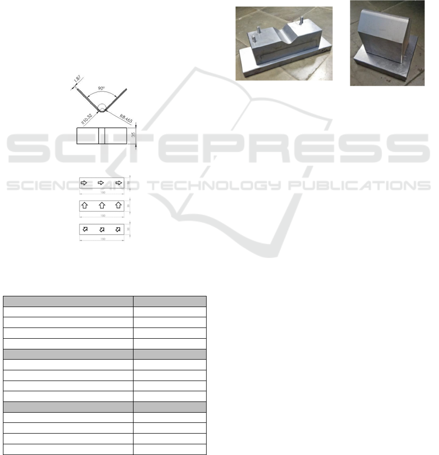
2.1 Bending Material Specifications
The material that is used for this v-test bending is
AISI 1005, with plate dimensions 150 × 35 × 1.87
(mm). The specimen is bent at 90° with an inner
radius of R8.465 and an outer radius of R10.32 and
the rolling direction is transverse, perpendicular and
45° with the direction of rolling as in Figure 2 and
Figure 3, and its mechanical properties are known as
follows.
Figure 2: Specimen specifications.
Figure 3: Direction of cutting the rolling plate of the
bending specimen.
Table 1: Data plate material with the direction of rolling.
Parameters Measurement Avera
g
e Avera
g
e
0.2% Y.S. [N/mm
2
] 221.967
Yield Stren
g
th
(γ)
[N/mm
2
] 223.697
Tensile Strength (σ) [N/mm
2
] 299.347
Elongation (ε) [%] 52.97
Parameters Measurement Average
0.2% Y.S. [N/mm
2
] 268.413
Yield Stren
g
th
(γ)
[N/mm
2
] 270.35
Tensile Stren
g
th
(
σ
)
[N/mm
2
] 324.11
Elongation (ε) [%] 51.593
Parameters Measurement Average
0.2% Y.S. [N/mm
2
] 253.543
Yield Stren
g
th
(γ)
[N/mm
2
] 259.226
Tensile Stren
g
th
(
σ
)
[N/mm
2
] 317.306
Elongation (ε) [%] 56.453
2.2 Making Tools
Tools made are vbending tools consisting of the 4
main components, namely, upper late with DIN
1.0037 material, punch bending with DIN 1.2510
material, die bending with DIN 1.2510 material, and
DIN 1.0037 bottom plate. Tools that made were
divided into 2 main parts, namely the bottom of the
tools and the top of the tools. The lower part of the
tools consists of the base plate, die bending an, and d
pin locator and the upper part consists of the upper
plate and the bending punch. The tools were made as
follows:
Figure 4: (a) The bottom of the tools, (b) The top of the
tools.
2.3 Testing and Measurement
Testing was carried out on the machine AIDA press
direct servo formers DSF-C1-A series Manufacturing
Engineering Laboratory Manufacturing Bandung.
This machine press uses a servo motor main drive so
that it allows for large presses and stable pressing
speeds
In the testing process, the engine speed used was
56 strokes/minute, and the holding time was 0
seconds. Furthermore, the angle formed in the
specimen is measured using a CMM (Coordinate
Measuring Machine) machine in the measurement
laboratory, in Manufacture Engineering Department.
3 CALCULATION AND
ANALYSIS
3.1 Prediction of Springback with
Formulas
The first step is using the formula of springback to
calculate the modulus of elasticity of the specimens
bending, for the calculation of elongation is used the
comparison formula between elongation peak before
breaking plates and elongation after plate breaks. The
calculations are as follows.
iCAST-ES 2022 - International Conference on Applied Science and Technology on Engineering Science
568

• Parallel
𝜀=
=
.%
.%
=1.33% (1)
• Perpendicular
𝜀=
=
.%
.%
=1.37% (2)
• 45°
𝜀=
=
.%
%
=1.38% (3)
So that the modulus of elasticity obtained is as
follows.
• Parallel
𝐸=
=
.
.%
=16689.25 𝑁/𝑚𝑚
2
(4)
• Perpendicular
𝐸=
=
.
.%
=19592.19 𝑁/𝑚𝑚
2
(5)
• 45°
𝐸=
=
.
.%
=18372.68 𝑁/𝑚𝑚
2
(6)
Next is calculating elastic modulus by entered the
formula springback to predict the final radius. Here
is the calculation of the springback final radius:
• Parallel
=4(
.
.
)
−3(
.
.
)+1 (7)
.
= 4(
.×.
.×.
)
−3(
.×.
.×.
) +1
.
=0.819
𝑅𝑓=10.317
• Perpendicular
=4(
.
.
)
−3(
.
.
)+1 (8)
.
=4(
.×.
. ×.
)
−3(
.×.
. ×.
) +1
.
=0.813
𝑅𝑓=10.412
• 45°
=4(
.
.
)
−3(
.
.
)+1 (9)
.
=4(
.×.
.×.
)
−3(
.×.
.×.
) +1
.
=0.809
𝑅𝑓=10.458
The next step is to calculate the amount of
springback using the formula for the k factor equation
of springback. Where it is known that the initial bend
angle (α
i
) is 180° minus the bending angle (89.98°) so
that the initial bend angle (αi) is 90.02° or 1,571
radians, so the calculation is as follows.
• Parallel
𝐾𝑠=
=
(10)
𝛼𝑓=1.571 𝑥
(
×.
.
)
(
×.
.
)
𝛼𝑓=1.312≈75.172°
• Perpendicular
𝐾𝑠=
=
(11)
𝛼𝑓=1.571 𝑥
(
×.
.
)
(
×.
.
)
𝛼𝑓=1.301≈74.542°
• 45°
𝐾𝑠=
=
(12)
𝛼𝑓=1.571 𝑥
(
×.
.
)
(
×.
.
)
𝛼𝑓=1.296≈74.255°
So that the magnitude of the prediction springback is
the difference between α
i
and α
f
.
• 𝑆𝑝𝑟𝑖𝑛𝑔𝑏𝑎𝑐𝑘 Parallel = 𝛼𝑖–𝛼𝑓=90.02°− 75.172° =
14.848°
• Perpendicular=𝛼𝑖−𝛼𝑓=90.02°−74.542°= 15.478°
• 𝑆𝑝𝑟𝑖𝑛𝑔𝑏𝑎𝑐𝑘 45° = 𝛼𝑖−𝛼𝑓 = 90.02° − 74.255°
=15.765°
The initial and final radius and the magnitudes of
the bend angle known as initial(α
i
) and bend angle
final (α
f
) can be used to calculate the k size of the
springback factor. The following is the calculation of
the k factor of springback.
• Parallel
𝐾𝑠=
=
(13)
𝐾𝑠=
=
.
.
=0.835
• Perpendicular
𝐾𝑠=
=
(14)
𝐾𝑠=
=
.
.
=0.828
• 45°
𝐾𝑠=
=
(15)
𝐾𝑠=
=
.
.
=0.825
Analysis of the Effect of AISI 1005 Grain Structure and Cutting Angle on Springback Using the V-Bending Method
569
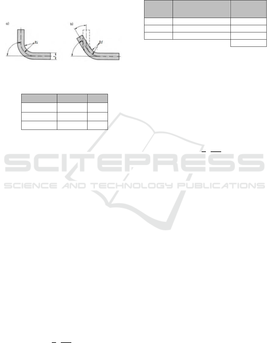
3.2 Prediction of Springback with
Tables
Figure 5 and table 2 below is a table to predict the
amount of springback with the influence of plate
material, radius punch and thickness of the plate.
Figure 5: Springback on bending (a) Before springback, (b)
After Springback.
Table 2: Table Springback (β).
t(mm) Ri(mm) β (°)
0.5 s.d. 0.7 1t s.d. 5t 5
0.8 s.d. 1.9 1t s.d. 5t 3
2 s.d. 4 1t s.d. 5t 1
So, to predict the amount of springback with this
analysis design, we can refer to the previous table 2.
Here is a prediction using table springback. It is
known:
AISI 1005 material parallel = 299,347 N / mm
2
(σ)
Perpendicular AISI 1005 material = 324.11 N / mm
2
(σ)
AISI 1005 material 45 ° = 317,306 N / mm
2
(σ)
Material thickness (t) = 1.87 mm.
Bending radius (radius punch) = R8.465 mm.
So that:
• Predict the size using the table, springback which
is 3°. Furthermore, to determine the magnitude of
the influence of the prediction springback using
table springback this, the next step is to calculate
the k factor of springback. The following is a
calculation of the k factor for springback using the
table springback.
𝑆𝑝𝑟𝑖𝑛𝑔𝑏𝑎𝑐𝑘=3°≈ 0.052 𝑟𝑎𝑑𝑖𝑎𝑛 (16)
• So that the magnitude of the bend angle final (αf)
is the difference between the bendsangel initial
(αi) and magnitude springback, with magnitude αi
= 90.02 ° or 1,571 radians. Here is a calculation to
find the size of αf and k factor springback.
𝑠𝑝𝑟𝑖𝑛𝑔𝑏𝑎𝑐𝑘= 𝛼𝑖−𝛼𝑓 (17)
𝛼𝑓=𝛼𝑖−𝑠𝑝𝑟𝑖𝑛𝑔𝑏𝑎𝑐𝑘=1.571−0.052=1.519 𝑟𝑎𝑑𝑖𝑎𝑛
𝐾𝑠=
=
.
.
=0.967
3.3 Analysis of Measurement Results
Table 3: The results of measurements.
No Cutting direction Average
1 Parallel 1.148
2 Perpendicula
r
-1.431
3 45° -1.716
-0.666
Next, the calculation of the k factor of springback
from the total average springback using v-bending
with the bend angle initial(αi) = 90.02 ° or 1,571
radians. Here is the calculation of the k factor for
springback.
𝑇𝑜𝑡𝑎𝑙 average 𝑠𝑝𝑟𝑖𝑛𝑔𝑏𝑎𝑐𝑘 = -0.666°
≈ -0.0116 𝑟𝑎𝑑
𝑠𝑝𝑟𝑖𝑛𝑔𝑏𝑎𝑐𝑘 = 𝛼
𝑖
−𝛼
𝑓
(18)
𝛼
𝑓
= 𝛼𝑖−𝑠𝑝𝑟𝑖𝑛𝑔𝑏𝑎𝑐𝑘 = 1.571−(-0.0116)
= 1.583 𝑟𝑎𝑑𝑖𝑎𝑛
𝐾𝑠=
=
.
.
=1.007
So that the results of the trials carried out are
different from the results using the formula
springback and the table springback as shown in table
4.1 above and can also be seen in the k factor of
springback. So that the magnitude of the value of
springback with the difference in the cutting angle of
the plate is quite influencing on the amount
of springback,
3.4 Calculation of Metal
Microstructure
After obtaining AISI 1005 metallographic data, then
quantitative metallographic analysis was carried out
to determine the average grain size of the 500x
magnification microstructure using the Planimetry
(Jeffries) method according to the ASTM E112
standard. As for below, the results of the calculation
of the grain size using the Planimetry method
(Jeffries).
iCAST-ES 2022 - International Conference on Applied Science and Technology on Engineering Science
570
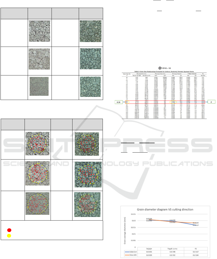
Table 4: Microstructure before the test bending and after the
test bending.
Before the
tes
t
Visual
After the
tes
t
Visual
Parallel
Parallel
Perpendicul
ar
Perpendicul
ar
45
0
45
0
Table 5: The results of the calculation of the grain size
before the test grain bending and after the test bending.
Before
the tes
t
Visual
After
the tes
t
Visual
Parallel
Parallel
Perpendi
cular
Perpend
icular
45
0
45
0
Information:
= Whole grain
= Clipped grain
(EXAMPLE)
Before bending the
parallel cutting It is known: Whole(n
1
) = 36
clipped grains (n
2
) = 24
Magnification (M) = 500x
Asked: ……… d?
f =
=
= 50
𝑁
𝑓 𝑛
𝑛
2
50 36
24
2
= 50 (48) = 2400/mm
2
G = [3,322 log N
A
] – 2,95
= [3,322 log 2400] – 2,95
= 11,23 – 2,95 = 8,28
Then from this G value is compared with the existing
standard in ASTM 112-12 for know the average grain
diameter size.
Figure 6: Grain Size Relationship Computed for Uniform,
Randomly Oriented, Equalaxed Grains in ASTM 112-12.
,,
,,
=
,
,
,
,
=
,
,
0,28d - 0.005292 = 0.00495 – 0,22d
0,5d = 0.010242
d = 0,0205 mm
From the ASTM E112-12 table for the value of G =
8.28, the average grain diameter is obtained of 0.0205
mm.
Figure 7: The effect of cutting direction on grain diameter.
From the results of the diagram above shows that
different cutting directions greatly affect the grain
size. In the AISI 1005 specimen before bending, it
shows that the grain with the largest diameter is
Analysis of the Effect of AISI 1005 Grain Structure and Cutting Angle on Springback Using the V-Bending Method
571
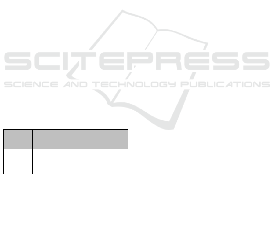
indicated by the grain with a parallel cutting direction
of 0.0205 mm, and the smallest grain is 0.0167 mm
with 45° cutting. Then the AISI 1005 specimen after
bending shows that the grain with the largest diameter
is shown by the grain with a parallel cutting direction
of 0.0209 mm, and the smallest grain is 0.0184 mm
with 45° cutting.
The effect of bending also affects grain size and
grain roughness. When the specimen is bent it will
make the average grain size larger. It can be seen that
in the parallel cutting direction, the grain size before
bending was 0.0205 mm, while the size after bending
was 0.0209 mm, there was an increase even though
the deviation was very slight by 4 x 10
-4
mm. At the
direction of cutting 45° is also the same, before
dibending grain size of 0.0167 mm while the size
after dibending of 0.0184 mm, an increase although
the deviation is very small at 17 x 10
-4
mm. However,
in the perpendicular cutting direction, there was an
increase in the average grain size, before bending by
0.0198 mm, while the size after bending was 0.0192
mm, there was a reduction even though the deviation
was very little by 6 x10
-4
mm.
4 CONCLUSIONS
Based on the results of the analysis in the previous
chapter, there are several conclusions including:
1. The cutting angle that produces springback with the
smallest deviation is parallel to the plate rolling angle
with a positive value of 1.148°, then the perpendicular
angle with a negative value of 1.431° and the largest
is 45° rolling with a negative value of 1.716°.
Table 6: Comparison of springback result.
No Cutting direction Average
1 Parallel 1.148
2 Perpendicular -1.431
3 45° -1.716
-0.666
So that the bending process is better to use a plate
with an angle in the direction of rolling between the
three angles that are used as a reference for the study.
2. The microstructure result is in Table 4.4 shows that
after doing bending all results in all directions cutting
have relatively the same grain shape, the direction of
cutting 45° deformed original grains become
relatively flat irregularly rounded. In the results
before bending, the grain boundaries are still tight, the
items between the items are still not stretched.
However, after bending, the grain experiences a
strain. The grain surface also undergoes roughening.
3. The grain with the largest grain diameter is
indicated by the grain with a parallel cutting direction
of 0.0205 mm, and the smallest grain is 0.0167 mm
with 45° cut. Then the AISI 1005 specimen after
bending shows that the grain with the largest grain
size is shown by the grain with a parallel cutting
direction of 0.0209 mm, and the smallest grain is
0.0184 mm with 45°cutting.
REFERENCES
Luchsinger, H.R. (1984). Tool design 2. Bandung:
Politeknik Mekanik Swiss-ITB.
Tschaetsch, H. Metal forming practise. Dresden: View
Verlag.
Suchy, I. (2006). Handbook of die design. New york: Mc
Graw-Hill Hand Books.
Budiarto. (2012). Sheet metal forming 2. Bandung:
Politeknik Manufaktur Bandung.
Kalpakjian, S. dan Schmid, S.R. (2008). Manufacturing
processes for engineering and technology. Jurong:
Pearson Education South Asia Pte Ltd.
Choudhury, LA. dan Ghomi, V. (2013). Springback
reduction of aluminium sheet in v-bending dies.
(jurnal). Kuala lumpur: SAGE.
Suprianto, J. (2000). Statistik-teori dan aplikasi. Jakarta:
Erlangga.
Kutner Nachtsheim, Neter, Li. (2004). Applied linier
statistical models. New york: Mc Graw Hill Book
Company.
Dieter, G.E. (1987). Mechanical Metallurgy. New York :
Mc Graw Hill Book Company.
Ostegaard, D.E. (1963). Basic die making.USA: McGraw-
Hill Book Company.
Rahmani, B. Alinejad, G. dkk. (2009). An investigation on
springback/negative springback phenomena using
finite element method and experimental approach.
(jurnal). Mazandaran: SAGE.
Vander Voort G.F, (1984). Metallography Principle and
Practice, McGrawHill. P.215,632.
Dieter, G. E.,& Bacon, D. (1988), Mechanical Metallurgy
SI Metric Edition. Journal of the Franklin Institue, 189.
Rodriguez, J. L., Perez-Benitez, J. A., Capo-Sanchez, J.,
Padovese, L. R., & Betancourt-Riera, R. (2008).
Dependence of Barkhausen jump shape on
microstructure in carbon steel. Revista mexicana de
física, 54, 127-129.
STANDARD, A. S. T. M., et al. Standard test methods for
determining average grain size. ASTM International,
West Chonshohocke, PA, 2013.
iCAST-ES 2022 - International Conference on Applied Science and Technology on Engineering Science
572
