
Design of Cradle as a Tool for Inserting Shaft in New Shipbuilding
Using Finite Element Methods
Budianto
a
, Rachmad Tri Soelistijono and Shihabuddin Afghoni
Shipbuilding Department, Politeknik Perkapalan Negeri Surabaya, Jalan Teknik Kimia, Surabaya, Indonesia
Keywords: Cradle, Inserting Shaft, New Shipbuilding, Design, Finite Element Method.
Abstract: The shipbuilding industry in Indonesia has experienced very rapid development. Innovation methods in
development have been improvised in time. In Indonesia, many shipyards have implemented the Full
Outfitting Block System (FOBS) methods. This method, especially in the machinery outfitting process in the
inserting shaft stage, takes a long time because it uses conventional methods with chain block tools. At PT.
PAL Indonesia has historically carried out inserting shafts using a cradle on the Missile Destroyer Ship project
(PKR) by recommendation from a foreign company and was able to minimize production time and costs. In
supporting the sustainability of the work efficiency of new shipbuilding, cradle design is very much needed
in the Inserting Shaft process on ships. The design process begins by making a design of 6 models of cradle
variations that are tailored to the needs of the shipyard. All these design variations were then subjected to a
strength analysis with the limits of allowable stresses and deflections from American Association of State
Highway and Transportation Official (AASTHO). The stress and deflection values obtained from each
variation of the design concept with all design concepts included in the allowable category.
1 INTRODUCTION
The shipbuilding industry in Indonesia has
experienced very rapid development. Innovation
methods in development have been improvised in
time. In Indonesia, many shipyards have
implemented the Full Outfitting Block System
(FOBS) methods. This method, especially in the
machinery outfitting process in the inserting shaft
stage, takes a long time because it uses conventional
methods with chain block tools. At PT. PAL
Indonesia has historically carried out inserting shafts
using a cradle on the Missile Destroyer Ship project
(PKR) by recommendation from a foreign company
and was able to minimize production time and costs.
In supporting the sustainability of the work
efficiency of new shipbuilding, cradle design is very
much needed in the Inserting Shaft process on ships,
where improvement and proper engineering are
needed for the inserting shaft process, this is very
important to escalate and ensure safety, quality
fulfilment, timely delivery. This will further reduce
the production cost of shipbuilding. Design and
analysis of the strength of the cradle construction in
a
https://orcid.org/0000-0002-4155-5008
supporting the load of the ship's shaft in the Inserting
Shaft process by paying attention to the position of
the shaft bearing that supported the cradle. This
analysis uses the finite element method using
Fusion360 software to determine the maximum stress
and maximum deflection that occurs in the cradle.
Where the structure of the cradle must comply with
the American Association of State Highway and
Transportation Official (AASHTO).
2 INITIAL DESIGN
At the initiation stage of the cradle design, several
reviews are needed of the components to be worked
on.
2.1 Cradle
The cradle consists of two parts, namely train sled and
shoes sled. A train sled or often referred to as a trolley
is a type of conveyance whose operation method is
pushed or handled by workers or operators manually
Budianto, ., Soelistijono, R. and Afghoni, S.
Design of Cradle as a Tool for Inserting Shaft in New Shipbuilding Using Finite Element Methods.
DOI: 10.5220/0011806800003575
In Proceedings of the 5th International Conference on Applied Science and Technology on Engineering Science (iCAST-ES 2022), pages 381-387
ISBN: 978-989-758-619-4; ISSN: 2975-8246
Copyright © 2023 by SCITEPRESS – Science and Technology Publications, Lda. Under CC license (CC BY-NC-ND 4.0)
381
in industrial plants or similar agencies. In general, a
shoes sled shipyard is a tool used for the docking
process (moving) the ship from the waters to the land
for repairs. Skates or often referred to as sliding ways
according to Meriam-Webster's Dictionary and
Thesaurus are the bottom part of the cradle on which
the ship is built and which slides over the ground
when launched or raised (Dictionary, 2006).
2.2 Stress
Stress can be interpreted as the intensity of the force
on the structural elements which is a reaction to the
deformation that arises due to the work of external
loads. Broadly speaking, stress is the magnitude of
the force acting on each unit of cross-sectional area
(Asroni 2017). So that stress can also be referred to as
a force that can withstand a load (Macdonald 2002).
2.3 Deflection
Deflection is a condition of changes in the shape of
the beam in the y-direction due to vertical loading
given to the beam or rod. Deformation in the beam is
very easily explained by the deflection of the beam
from its position before being subjected to loading.
The deflection is measured from the initial neutral
surface to the neutral position after deformation. A
structural system that is placed horizontally and
which is mainly intended to carry lateral loads namely
loads that act perpendicular to the axial axis of the rod
(Hariandja, 1996). The maximum allowable
deflection according to the American Association of
State Highway and Transportation Official
(AAHSTO) is the maximum deflection of the bridge
construction (Restrepo 2002), not more than:
2.4 Deflection
The moment is the result of multiplying the force with
the distance from the force to the point (Widiyanto
2013). The moment equation can be written in this
Equation as refer rule regulation.
In the condition of the force that has a different
capture point, where the point of capture of the force
with each other has a distance so that the moment
occurs. Then the number of moments at one point
equal to zero can be seen in this equation as follows
actual maximum bending moment.
2.5 Safety Factor
Safety Factor is a factor that shows the level of ability
of an engineered material from external loads to
handle pressure loads and tensile loads. The safety
factor can be determined in equation 3 as follows
(Budianto, Strength Structure Analysis of Main Gate
Graving Dock Using 2018).
The value of the safety factor must be greater than
1.0 in order to avoid failure. If the factor of safety is
very low, the probability of failure will be high, and
the structure will not be acceptable. If the factor of
safety is too large, the structure will be wasteful of
materials and may not be suitable for its function, e.g.,
too heavy. Due to this complexity and uncertainty, the
factor of safety must be determined probabilistically.
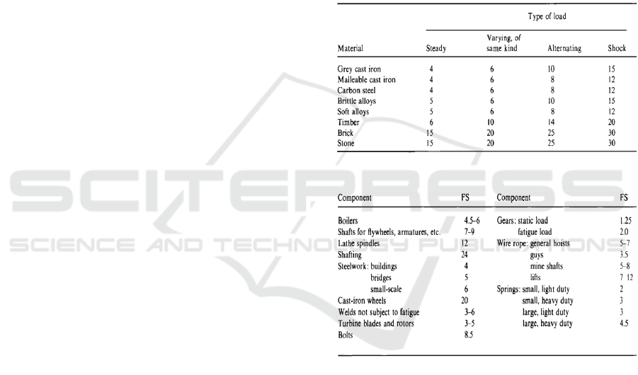
The following is the Typical Overall Factor of Safety
table according to the Mechanical Engineer's Data
Handbook as follows (Carvill 1993).
Figure 1: Typical factor of safety for various materials.
Figure 2: Typical factor of safety for various components.
2.6 Load
Loading is a load that burdens a construction in the
form of object weight, wind strength, and wind
weight (Priambodo, 2011). These charges have
magnitude, direction, and line of action. In the cradle
construction that has been made, there is only one
loading, namely vertical loading (M.Gere and
S.P.Timoshenko 1994).
2.7 Finite Element Method
The finite element method was originally used to
solve complex problems in the field of Civil
iCAST-ES 2022 - International Conference on Applied Science and Technology on Engineering Science
382

Engineering and Aeronautical Engineering,
especially on elasticity problems and structural
analysis (Budianto, Analisis Kekuatan Struktur pada
Kapal Wisata Sungai Kalimas 2015). This is much
more practical and economical when designing a
design before making it a physical prototype (Naruto,
2019). The finite element method is a numerical
method used in solving problems in various
engineering fields such as the geometry, loading, and
properties of very complex materials. In addition, this
method can also be used to solve structural, thermal,
and electromagnetic problems (Morna 2012).
Problem-solving in the finite element method is a
solution approach to find the displacement of the
element's discrete nodes and the strength of the
structure (Budianto, Strength Structure Analysis of
Main Gate Graving Dock Using 2018).
In this method, all complex problems such as
variations in shape, boundary conditions, and loads
are solved by an approximation method. The finite
element method approach uses the information at the
node. In the process of determining the node points
called discretization, a system is divided into smaller
parts, then problem-solving is carried out on these
parts and then recombined to obtain a comprehensive
solution (Logan 2005). The descriptions carried out
can be in the form of one-dimensional elements (line
elements), two-dimensional (shell field elements), or
three-dimensional (solid elements or continuum)
(Budianto, 2018). In structural analysis, the finite
element method analysis can be used to solve
deflections and stresses in complex structures that
receive certain loads at appropriate boundary
conditions (Asmara and Budianto 2016)
3 CONCEPT DESIGN
Collecting data to support the design process is a
General Arrangement of Shaft Line design drawing
of the highest weight ever produced by PT. PAL
Indonesia (Persero). In addition, in planning the
cradle design, comparative design data is needed as a
basis for planning dimensions for making a new
design on the cradle where this data is taken from the
cradle design that has been used before by the
company. The data that has been collected will be
used as a basis for designing and planning the shape
of the cradle. The general arrangement of the Shaft
Line is used to determine the load borne by the
planned Cradle.
In this case, because the load supported by the
cradle is a shaft that has a relatively heavy weight, the
cradle is designed with materials that can be found on
the market and are also economical in price so that the
material is obtained in the form of plate-shaped steel
with ASTM 36 type with specifications as shown in
the following table.
Table 1: Specification of ASTM 36 steel.
ASTM A36 Steel
Mechanical
Properties
Ultimate Tensile
Strength
400–550
MPa
Yield Tensile Strength 250 MPa
Elongation at Break
(200cm)
20,0 %
Modulus of Elasticity 200 GPa
After obtaining supporting data, the next step is
planning from the cradle shape. In this planning, the
sled design is made with almost the same shape as the
sled that has been used before because the shape
adjusts to the shape of the pedestal of the shaft that
has been planned by the vendor and for the skates,
variations are made with different girder shapes and
construction patterns as shown in the following table.
Table 2: Variations of design.
From these variations, a model will be made with the
following scheme.
Figure 3: Design Variation Relationship Patter.
The cradle consists of a train sled and shoes sled with
cradle modeling done using Fusion 360 software as
follows.
Figure 4: Design of the Shoes Sled Variations.
Part 1 2 3
Girder
(G)
I Shape
Hollow
Patterm
(P)
Triangle
Cross X
Square
Box
Design of Cradle as a Tool for Inserting Shaft in New Shipbuilding Using Finite Element Methods
383
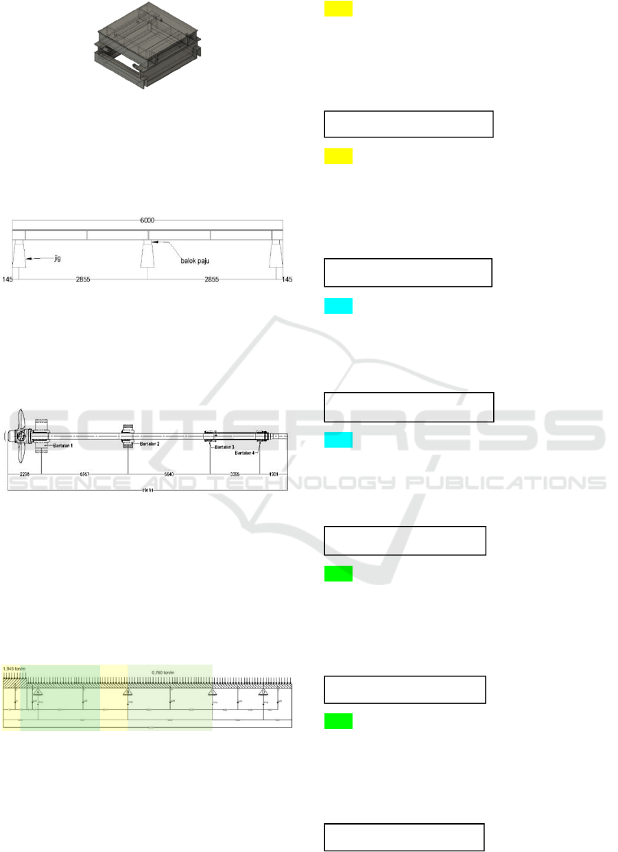
Figure 5: Design of the Train Sled.
In the assembly of the cradle, it is necessary to plan
the positioning of the pedestal of the cradle, where it
is planned that one cradle has three supports which
are placed at both ends and the middle position of the
cradle as shown in the following schematic image.
Figure 6: Cradle Leg Arrangement Sketch.
This cradle has a load in the form of a shaft placed on
a sled with a configuration that adjusts to the bearing
position that has been planned by the maker of the
shaft in the shaft dimension drawing and the
following shaft bearing arrangement.
Figure 7: Shaft Dimensions and Shaft Bearing Arrangement.
It is necessary to calculate the load at each point
of the shaft bearing to obtain the load value that will
be used as a reference for strength analysis. From the
dimension and arrangement data, it can be used as a
reference in calculating the load that will be borne by
the cradle at each point of the shaft bearing by
carrying out the calculations illustrated in the
following sketch.
Figure 8: Shaft Load Distribution Sketch.
This calculation can be done using the equation of
moment and balance. The moment is the result of
multiplying the force with the distance from the force
to the point (Widiyanto, 2013), which can be written
with equations 1 and 2 with the following
calculations.
∑M
A
= 0
(-3.026 ton × 1.5200 m) - (0.564 ton × 0.3710 m) +
(4.527 ton × 2.9753 m) – (RVB × 5.9570 m)
= 0
8.6749055 – 5.957 RVB
= 0
∑M
B
= 0
(4.527 ton × 2.978 m) - (RVA × 5.957 m) + (0.564
ton × 6.328 m) + (3.026 ton × 7.477 m)
= 0
39.6758 – 5.957 RVB
= 0
∑M
B
= 0
(4.286 ton × 2.820 m) - (RVC × 5.640 m)
= 0
12.08652 – 5.640 RVC
= 0
∑M
C
= 0
(4.286 ton × 2.820 m) - (RVB × 5.640 m)
= 0
12.08652 – 5.640 RVB
= 0
∑M
C
= 0
(2.580 ton × 1.697 m) - (RVD × 3.395 m) + (1.445
ton × 4.3455 m)
= 0
10.6575075 – 3.395 RVD
= 0
∑M
D
= 0
(-1.442 ton × 0.9505 m) + (2.580 ton × 1.697 m) -
(RVC × 3.395 m)
= 0
3.0047875 – 3.395 RVC
= 0
RV
B
= 1,456254871
RV
A
= 6.660365456
RV
C
= 2.143 ton
RV
B
= 2,143 ton
RV
D
= 3,139177467
RV
C
= 0.885062592
iCAST-ES 2022 - International Conference on Applied Science and Technology on Engineering Science
384
After calculating the value of the reaction force,
correction is made by comparing the values of q
1
, q
2A
,
q
2B
, q
2C
, q
2D
, and q
2E
with RV
A
, RV
B
, RV
C
, and RV
D
equal to one with the following calculations.
Correction = (3.02642 + 0.56392 + 4.52732 +
4.2864 + 2.5802 + 1.44475) /
(6.660365456 + 3.599254871 +
3.02806392 + 3.139177467)
= 16.43 / 16.43
= 1 (accepted)
From the calculation of the value of the reaction
force, the shaft load point can be taken for simulating
cradle loading with the summary in the following
table.
Table 3: Summary of Shaf Load Value.
Pos. Load Value
A 6.660365456 ton
B 1.456254871 + 2.143 = 3.599254871 ton
C 2.143 + 0.885062592 = 3.028062592 ton
D 3.139177467 ton
Total 16.43 ton
After obtaining the load value at each supported
point, then the highest load value is taken, namely
6.66 tons, as the load value for the simulation.
Because this is a design process, it is necessary to
carry out further calculations to determine the design
load value as in equation 4 with the following
calculations.
P
design
= 6.660 kg × 1,25
= 8.325 kg
F
design
= 8.325 kg × 9,81
= 81668.25 N
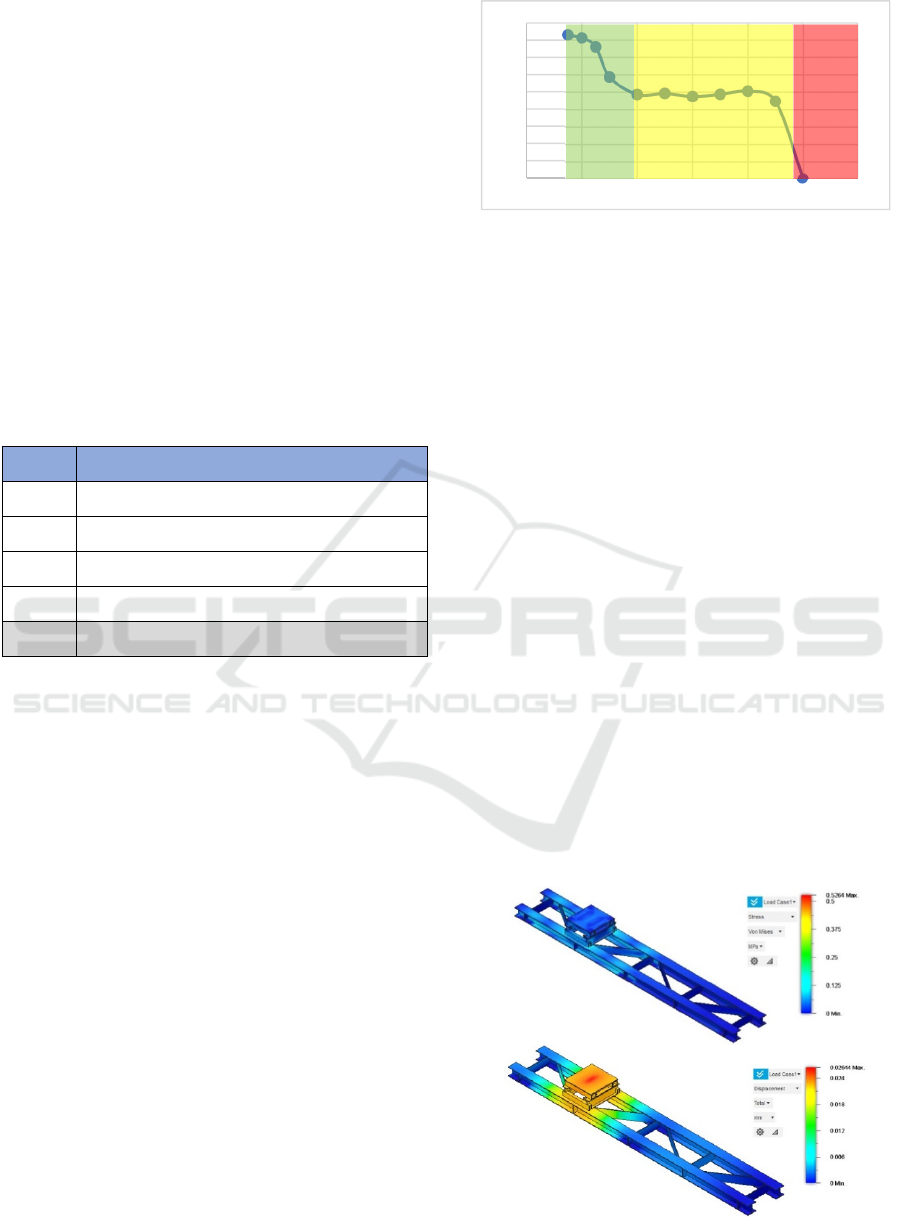
After obtaining the Fdesign value, then a strength
analysis is carried out. To obtain accurate finite
element analysis results, it is necessary to adjust the
element size by conducting a meshing convergence
test. So that the element size is 150mm as shown in
the following graph.
Figure 9: Meshing Convergence Graph.
4 RESULT AND DISCUSSION
After obtaining the F design value, a meshing
convergence test was carried out and the element size
was obtained at 150mm, then a simulation of each
design concept was carried out with a perfect circuit
together with the train sled. The maximum stress
results from the simulation are compared to the
maximum allowable stress value that occurs in
structures having a Safety Factor (SF) of 5.0 in the
typical overall safety of factor table (referring to
Tables 1 & 2) so that the bending stress value is
obtained. The maximum of the cradle is.
The maximum deflection results from the
simulation are compared to the maximum allowable
deflection value in accordance with the regulations of
the American Association of State Highway and
Transportation Official (AAHSTO) as in equation 1
is shown below.
The simulation can be done with Fusion 360
software by inputting the type of material, the
constraints on the cradle legs, and also the size of the
elements according to the convergence results of 150
mm. so that the simulation results are obtained in each
of the following six models.
Figure 10: (a) Stress Result of Model 1; (b) Displacement
Result of Model 1.
0,000
1,000
2,000
3,000
4,000
5,000
6,000
7,000
8,000
9,000
0 200 400 600 800 1000 1200
Design of Cradle as a Tool for Inserting Shaft in New Shipbuilding Using Finite Element Methods
385
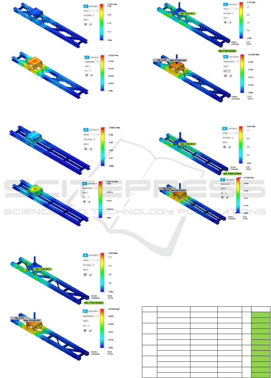
Figure 11: (a) Stress Result of Model 2; (b) Displacement
Result of Model 2.
Figure 12: (a) Stress Result of Model 3; (b) Displacement
Result of Model 3.
Figure 13: (a) Stress Result of Model 4; (b) Displacement
Result of Model 4.
Figure 14: (a) Stress Result of Model 5; (b) Displacement
Result of Model 5.
Figure 15: (a) Stress Result of Model 6; (b) Displacement
Result of Model 6.
From all simulation results, each stress and
displacement value is obtained, then validation is
carried out with the allowable stress and permit
displacement which have been calculated according
to regulations and the results are obtained in the
following table.
Table 4: Strength analysis results.
Model Type of Analysis Maximum Allowable SF Status
1
Stress 0.526 N/mm
2
110 N/mm
2
5
Allowed
Displacement 0.026 mm 1.586 mm Allowed
2
Stress 0.508 N/mm
2
110 N/mm
2
5
Allowed
Displacement 0.025 mm 1.586 mm Allowed
3
Stress 0.098 N/mm
2
110 N/mm
2
5
Allowed
Displacement 0.005 mm 1.586 mm Allowed
4
Stress 8.045 N/mm
2
110 N/mm
2
5
Allowed
Displacement 0.079 mm 1.586 mm Allowed
5
Stress 8.302 N/mm
2
110 N/mm
2
5
Allowed
Displacement 0.080 mm 1.586 mm Allowed
6
Stress 8.065 N/mm
2
110 N/mm
2
5
Allowed
Displacement 0.077 mm 1.586 mm Allowed
iCAST-ES 2022 - International Conference on Applied Science and Technology on Engineering Science
386

5 CONCLUSIONS
The cradle is designed with ASTM 36 Steel material
with 6 different models, where in the analysis results
the six models are in the conditions allowed by
regulation. of the six models, model 3 has a relatively
lower stress value than all models with a value of
0.098 N/mm
2
and also has a relatively lower
displacement value than all models with a value of
0.005 mm. So that model 3 has a tendency to be used
as a reference model in making the cradle because it
has a higher strength than all the models made.
The 3rd concept cradle is made in the form of a
girder I shape. This concept shoes sled is given a
reinforcement construction with a square box pattern
made of 12 mm thick plate and for the middle
reinforcement made of 10mm thick plate, both of
which have been adjusted to the position of the welder
during welding.
ACKNOWLEDGEMENTS
The author is grateful to the lecturers colleague of the
Shipbuilding Institute of Polytechnic Surabaya for all
the knowledge sharing, especially in the design and
analysis of finite elements to carry out this research
work.
REFERENCES
Asmara, I Putu Sindhu, and Budianto. (2016). "Analisa
Kekuatan Deck Crane pada Kapal Tol Laut Nusantara."
Seminar Nasional Maritim, Sains, dan Teknologi
Terapan 29-34.
Asroni, A. (2017). Teori dan Desain Balok Plat Beton
Bertulang Berdasarkan SNI 2847-2013. Surakarta:
Muhammadiyah University Press.
Budianto. (2015). “Analisis Kekuatan Struktur pada Kapal
Wisata Sungai Kalimas.” Kapal 8-18.
Budianto. (2018). "Strength Structure Analysis of Main
Gate Graving Dock Using." Makara J. Technol 109-
114.
Carvill, James. (1993). Mechanical Engineer's Data
Handbook. Oxford: Elsevier Science Ltd.
Hariandja, Binsar. (1996). Analisis Lanjut Sistem Struktur
Berbentuk Rangka. Jakarta: Penerbit Erlangga.
Logan, DL. (2005). A First Course in The Finite Element
Method. Platteville: University of of Wisconsin.
McCreary, D. R., & Amacker, E. (2006). Experimental
Research on College Students' Usage of Two
Dictionaries: A Comparison of the Merriam-Webster
Collegiate Dictionary and the Macmillan English
Dictionary for Advanced Learners, 871-885.
Dictionary, M. W. (2006). The Merriam-Webster
Dictionary. Merriam-Webster, Incorporated.
Priambodo, G. (2011). Technical and social impacts of
wastewater from fish processing industry in Kota
Muncar of Indonesia. Journal of Applied Technology in
Environmental Sanitation, 1(1), 1-7.
MacDonald, M. P., Paterson, L., Volke-Sepulveda, K., Arlt,
J., Sibbett, W., & Dholakia, K. (2002). Creation and
manipulation of three-dimensional optically trapped
structures. Science, 296(5570), 1101-1103.
Restrepo, L., Wityk, R. J., Grega, M. A., Borowicz Jr, L.,
Barker, P. B., Jacobs, M. A., ... & McKhann, G. M.
(2002). Diffusion-and perfusion-weighted magnetic
resonance imaging of the brain before and after
coronary artery bypass grafting surgery. Stroke, 33(12),
2909-2915.
Widiyanto, A. (2013). Agroforestry dan peranannya dalam
mempertahankan fungsi hidrologi dan konservasi. Al-
Basia, 9, 55-68.
Naruto, H., & Togo, H. (2019). Preparation of 2-
arylquinolines from β-arylpropionitriles with
aryllithiums and NIS through iminyl radical-mediated
cyclization. Organic & Biomolecular Chemistry,
17(23), 5760-5770.
Morna, A. (2012). Research on contribution of agriculture
to economic growth of the North-West region. Analele
Universității din Oradea, Fascicula: Protecția
Mediului, 19, 129-132.
Design of Cradle as a Tool for Inserting Shaft in New Shipbuilding Using Finite Element Methods
387
