
Safety Integrated Level Analysis and Risk Management in Steam
Drum Based on the Octave Software
Hendrik Elvian Gayuh Prasetya, Muhammad Faldy Ortada and Radina Anggun Nurisma
Powerplant Engineering Department, Politeknik Elektronika Negeri Surabaya, Surabaya, Indonesia
Keywords: Safety Integrated Level, Octave, Steam Drum.
Abstract: As the Level of risk increase, better protection systems are needed to control them. One way to find out the
system's performance is Safety Integrated Level. SIL is a degree of SIF able to implement necessary risk
mitigation successfully. SIF comprises sensors, a Logic Solver, and final control elements. In this study, the
safety levels of the steam drums use the SIL method, with nodes studies on temperature, pressure, and levels.
The logic solver used a DCS solver, and Finale control elements used the main steam valve, valve separator,
and water steam valve. Calculate SIL value using Excel and Octave software. Octave software is used to
determine the level of safety on components automatically. The SIL calculations obtained a PFD value from
a sensor at 0.0242656, PFD from the logic solver at 0.01171875, and PFD from the final control element was
0031280256. Based on the PFD value that has been obtained, PFD would be quantified and average PFD
average by 0.067781661, thereby landing a risk reduction factor (RRF) of 14.75325. Drum steam can be
categorized as having a safety integrated level (SIL) 1. the level of safety on the steam drum component is
classified as safe. By consistently doing regular maintenance.
1 INTRODUCTION
A steam drum is one of the components of the water
pipes that serve as reservoirs of water and water vapor
and separate water vapor from water in forming
superheater steam. In the steam of the drums, water is
pumped by the boiler-circulation pump to the raisins
tube/wall tube to get to the saturation vapor phase
(Eliza Marceliana Zeinda,2017)
In Indonesia, job accidents occur in a plant
environment caused by workers and plant
components. According to the steam laws of 1930 and
law no. 1 in 1970 on job safety that companies using
the boilers were obliged to do an OHS program to
reduce the number of accidents. A company needs
protection and work in its business. So, it needs to
apply risk management (Steam laws Kemnaker,
1930).
Every power plant has a standard for
implementing risk management. It is critical because
it concerns the reliability of an instrumentation
system. As the danger is vital, better protection
systems must control it. One method used to
determine the performance is using the safety system
(SIL) method (Vimalasari,2016).
SIL is a degree of SIF able to implement necessary
risk mitigation successfully. The SIF of SIS is usually
composed of sensors, programmable logic breakers,
and late control elements (FCE). SIL herself refers to
the possibility of SIF failure (PFD). The higher the
SIL value, the PFD of SIS gets lower. The value of
PFD of each determines the SIL level of an SIS - each
SIF of the SIS itself, the sensors, logic solver, and
finale of element control (Fitrani Kamila,2016)
The safety integrated Level (SIL) is separated into
four levels based on IEC 61508, SIL 1, SIL 2, SIL 3,
and SIL 4. The above criteria, which is both
qualitative and quantitative, provides a foundation for
determining SIL in general. The important test
criteria of the products generated determine the
formulation of a category SIL evaluation. Fire,
materials quality, mechanical impact, electronic
operation, and leak tests are just a few examples
(Fitrani Kamila,2016).
This follows the need for a study to identify any
potential dangers to the system and is expected to be
able to recommend proper maintenance so that the
components in the system can function properly, can
identify a systematic operating process, and
determine any deviation in the process that could lead
to unwanted accidents or accidents.
278
Prasetya, H., Ortada, M. and Nurisma, R.
Safety Integrated Level Analysis and Risk Management in Steam Drum Based on the Octave Software.
DOI: 10.5220/0011759700003575
In Proceedings of the 5th International Conference on Applied Science and Technology on Engineering Science (iCAST-ES 2022), pages 278-283
ISBN: 978-989-758-619-4; ISSN: 2975-8246
Copyright © 2023 by SCITEPRESS – Science and Technology Publications, Lda. Under CC license (CC BY-NC-ND 4.0)
2 ANALYSIS METOD
2.1 Safety Integrated System
A Safety Instrument System is a collection of sensors,
logic solvers, and final parts designed to protect the
system in the event of a defiant operation without
endangering people, the environment, or a valuable
item
2.1.1 Sensor
The sensor is made up of several devices that monitor
the process, such as transmitters and transducers. The
sensor transforms physical data into electrical data
that can be evaluated with an electric circuit
2.1.2 Logic Solver
The logic solver is a processor that takes an electric
signal from one or more sensors and converts it into
electric signals that are supplied to the final element
2.1.3 Finale Control Element
The final control element is part of the SIS, and its
purpose is to act to return to a safe state. The valves
and actuators are the last component.
2.2 Safety Instrument Function
SIF refers to a set of tools designed to lower the risk
of a given danger. SIF is a non-profit organization.
When defined conditions are breached, automatically
bringing an industrial process to a safe state, allowing
a method to move forward safely when stated
conditions allow, and taking measures to reduce the
consequences of an industrial hazard. It consists of
elements that recognize an impending hazard, decide
to act, and then put in the necessary effort to bring the
process to a safe state.
2.3 Safety Integrated Level
SIL is a level of SIF that can successfully perform risk
mitigation. Sensors, programmable logic solvers, and
Finale Control elements are commonly found in the
SIS SIF (FCE). The Safety Integrated Level test is
used to determine whether a system is safe.
SIL ratings correlate to the frequency and severity
of hazards. They determine the performance required
to maintain and achieve safety and the probability of
failure. The higher the SIL, the greater the risk of
failure. And the greater the risk of failure, the stricter
the safety requirements.
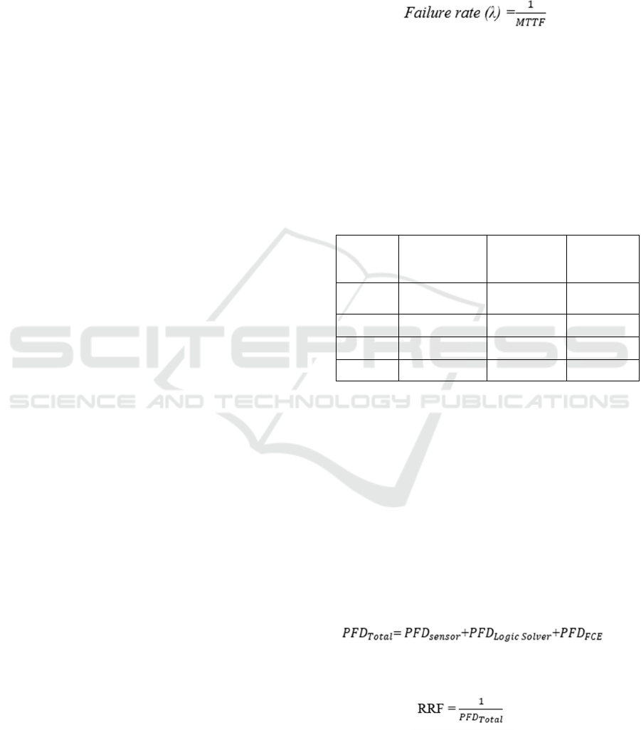
The SIL value is calculated using maintenance
data for each piece of BPCS-related equipment. This
data on maintenance aids in determining the MTTF
(Mean Time to Failure).
While the failure rate is calculated using the
equation:
(1)
Then, after the failure rate is known, the PFD
value is calculated using the equation:
PFD=1/2 *λ*Ti (2)
where:
PFD = Probability of Failure on Demand
λ = failure rate (hour)
Ti = test interval (hour)
Table 1: SIL and required safety system performance low
demand mode system.
Safety
Integrated
Level (SIL)
Probability
Failure on
Demand (PFD)
Safety
Availability
(1_PFD)
Risk
Reduction
Factor (RRF)
4
0.0001 – 0.00001
99.99 –
99.999%
10000 –
100000
3 0.001 – 0.0001 99.9 – 99.99% 1000 – 10000
2 0.01 – 0.001 99 – 99.9% 100 – 1000
1 0.1 – 0.01 90 – 99% 10 – 100
Table 1 illustrates that the system's higher PFD
value necessitates a high level of safety. To put it
another way, the more serious the failure, the higher
the level of safety required to verify that the plan is
safe to use. It also demonstrates that the program
requires extra safety procedures to protect it from
failure.
Probability of failure on demand (PFD) is the
probability that a system will fail dangerously and not
be able to perform its safety function when required
Computing the PFD for each SIF made up of the
SIS and then calculating the overall PFD for the SIF
can be used to calculate the SIL. The following
equation is used to calculate the total PFD.
(3)
From the total it can be seen the value of risk
reduction factor, RRF as follows:
(4)
Safety Integrated Level Analysis and Risk Management in Steam Drum Based on the Octave Software
279
2.4 Octave
An octave is a GNU software used for numerical
analysis and is equivalent to MATLAB software
capabilities. This study uses octave software to
automatically perform calculations and determine the
steam drum's level of safety. Thus, choosing the SIL
level on the steam drum component.
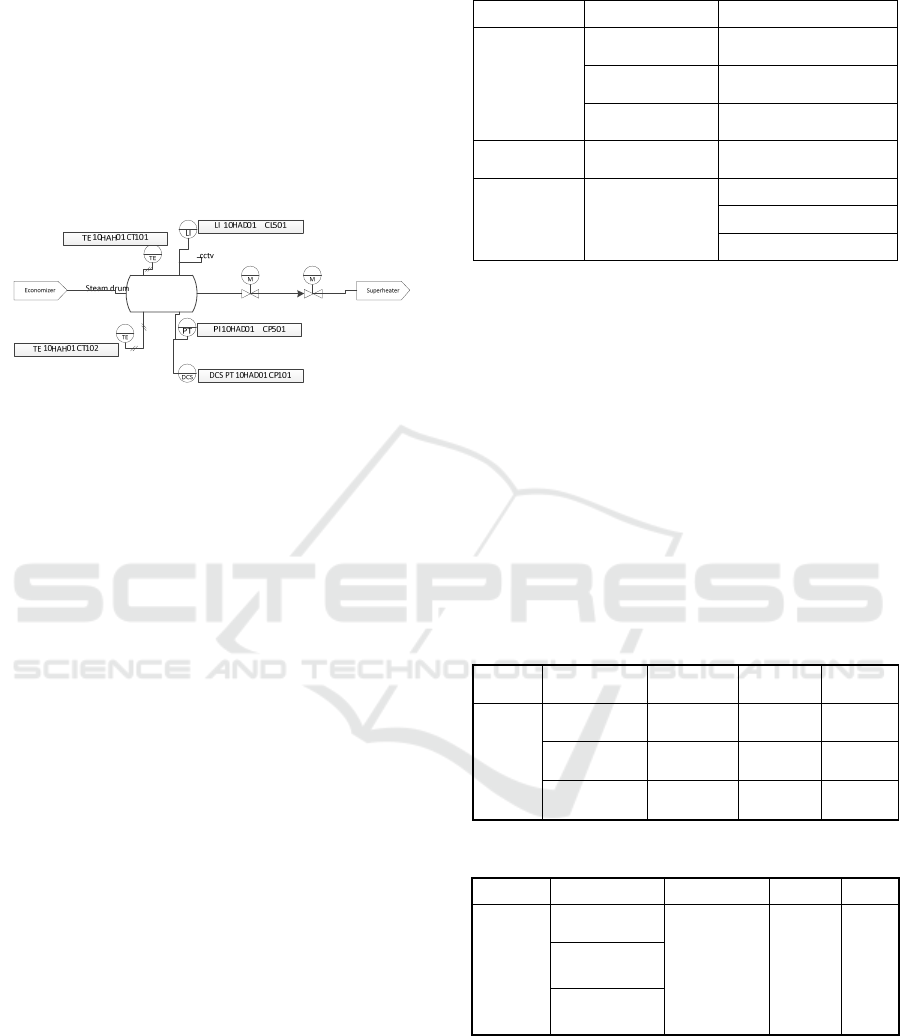
2.5 P&ID Steam Drum
Figure 1: P&ID steam drum.
P&ID (pipe and instrumentation diagram) is a
schematic of a process system's pipeline, equipment,
instrumentation, and control system. The picture
above shows several instrument temperatures,
pressures, and levels, with TE CT101 as the input
temperature sensor on the steam drum, which comes
from the economizer output temperature. The sensor
has CCTV, which functions to determine the value of
the sensor needed by the local operator to see its value
and the condition of the steam drum.
In addition, the steam drum also has a pressure
transmitter sensor at the steam drum's output to
determine the pressure value. And has a Level
indicator to find out how much % the condition of the
water level in the steam drum is. For the logic solver
on the Steam Drum, DCS sends signals to the PLC
and the CCR if there are other problems. After that,
the steam drum has several final control elements in
the form of valves such as the main steam valve,
water valve, and separator valve.
2.6 Study Node
The study node's determination is based on the
frequency of danger on the steam drum in the form of
sensors, logic solver, and Finale control element. The
resolution of the study node is obtained from the
steam drum maintenance data.
Table 2: Study node steam drum.
SIS Component Component
Sensors
TE 10HAH01
CT101
TE 10HAH01 CT101
LI 10HAD01
CL501
LI 10HAD01 CL501
PI 10HAD01
CP501
PI 10HAD01 CP501
logic solver
DCS PT
10HAD01 CP101
DCS PT 10HAD01
CP101
finale control
element
actuator
Main Steam Valve
Valve separator
Water Steam Valve
3 SIL CALCULATION
3.1 Sensor
According to the study node data received from the
steam drum maintenance data, the steam drum
includes three sensors: a temperature sensor, a
pressure sensor, and a level sensor. The sensor has
been repaired, and the Time to Failure has been
calculated (TTF). The value of the Mean Time to
Failure (MTTF) can be calculated using the TTF data,
and then used to calculate the PFD value and failure
data.
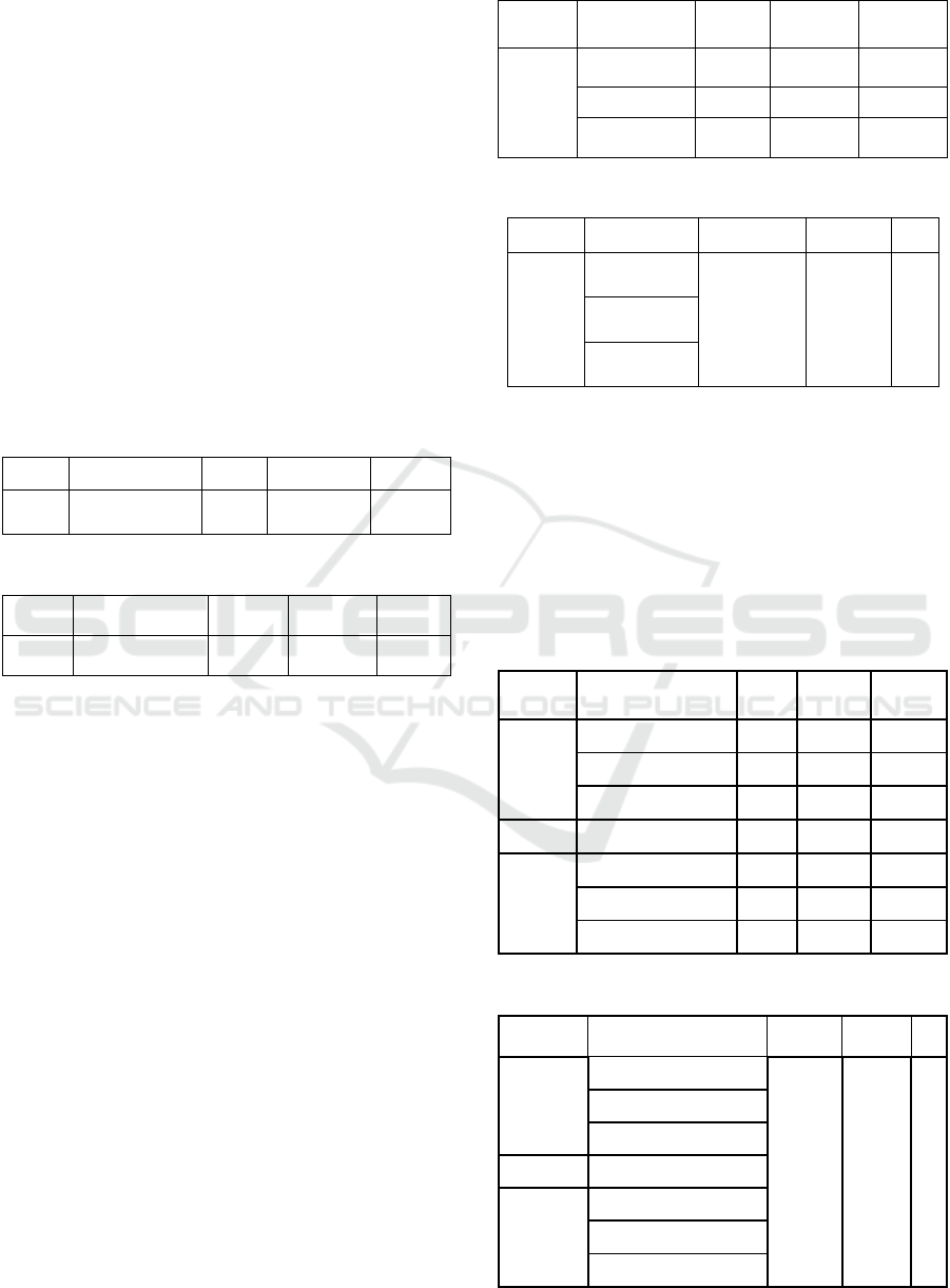
Table 3: Safety integrated level sensors.
SIS components MTTF
Failure
Rate
PFD
sensor
TE 10HAH01
CT101
5772 0.000173 0.008316
LI 10HAD01
CL501
5816 0.000172 0.008253
PI 10HAD01
CP101
5844 0.000171 0.008214
Table 4: Safety integrated level sensors.
SIS components PFD average RRF SIL
sensor
TE 10HAH01
CT101
0.024783 40.3508 1
LI 10HAD01
CL501
PI 10HAD01
CP101
The MTTF value for each sensor is different,
according to the equations above. The temperature
sensor measures 5772, the pressure sensor measures
6816, and the level sensor measures 5844. The failure
rate values of each temperature sensor, pressure
sensor, and level sensor are 0.000173, 0.000172, and
0.000171, respectively, based on the computation (1)
iCAST-ES 2022 - International Conference on Applied Science and Technology on Engineering Science
280
to estimate the failure rate value. After obtaining the
failure rate, we can use the formulas (2) to compute
the PFD and RRF for each sensor (4). The sensors
system can be classified into SIL 1 with a PFD
average value of 0.024783 and RRF 40.3508
3.2 Logic Solver
This steam drum uses a logic solver distributed
control system (DCS). DCS is an integrated system
using controllers, communication, protocols, and
computer that can make it easier for users to control
equipment using analog or digital signals from a
control room.
The programmable logic controller (PLC) and
other controllers are under DCS. So, this SIF is very
crucial. If it is damaged, it can result in a data signal
not being sent to the control room.
Table 5: Safety integrated level logic solver.
SIS component MTTF Failure Rate
PFD
logic
solver
DCS PT
10HAD01 CP101
4096 0.000244
0.011719
Table 6: Safety integrated level logic solver.
SIS component
PFD
average
RRF SIL
logic
solve
r
DCS PT
10HAD01 CP101
0.011719 85.33333 1
After performing calculations based on
maintenance data, the MTTF value in the logic solver
is 4096. Based on the above calculations, the
following PFD and RRF values are obtained
0.011719 and 85.333. So, the logic solver can be
categorized into SIL 1.
3.3 Final Control Element
The final element is part of the SIS, and its purpose is
to act to return to a safe state. The valves and
actuators are the final element. The main steam valve,
water valve, and separator valve are the final control
elements in the steam drum.
Based on the calculation of the MTTF value, the
MTTF of each FC is different. The failure value in
FCE is obtained from the maintenance data, such as
preventive maintenance data and damage in FCE.
After getting the MTTF value, can receive each FCE
component's PFD value to find the PFD average value
and the RRF value on the FCE. Based on these
calculations, it was found that the average PFD value
is 0.03128, and the RRF value is 31.96905 so, so the
FCE can be categorized into SIL 1.
Table 7: Safety integrated level finale control element.
SIS components MTTF
Failure
Rate
PFD
finale
control
element
Main Steam
Valve
5160 0.000194 0.009302
Valve separator 3569 0.00028 0.013449
Water Steam
Valve
5628 0.000178 0.008529
Table 8: Safety integrated level finale control elements.
SIS
components PFD average RRF
SIL
finale
control
element
Main Steam
Valve
0.03128 31.96905
1
Valve
separato
r
Water Steam
Valve
3.4 Safety Integrated Level Steam
Drum
The value of the Safety Integrated Level (SIL) can be
computed based on the failure data that happens in the
instrument on the Steam Drum component to identify
the level of safety on the Steam Drum component and
the PFD (Probability Failure Demand) value.
Table 9: Safety integrated level on the steam drum.
SIS components MTTF
Failure
Rate
PFD
Sensor
TE 10HAH01 CT101 5772 0.000173 0.008316
LI 10HAD01 CL501 5816 0.000172 0.008253
PI 10HAD01 CP101 5844 0.000171 0.008214
l
ogic solve
r
DCS PT 10HAD01 4096 0.000244 0.011719
finale
control
element
Main Steam Valve 5160 0.000194 0.009302
Valve separator 3569 0.00028 0.013449
Water Steam Valve 5628 0.000178 0.008529
Table 10: Safety integrated level on the steam drum.
SIS component
PFD
average
RRF SIL
Sensor
TE 10HAH01 CT101
0.067782 14.75325 1
LI 10HAD01 CL501
PI 10HAD01 CP101
logic solver DCS PT 10HAD01 CP101
f
inale contro
l
element
Main Steam Valve
Valve separator
Water Steam Valve
Safety Integrated Level Analysis and Risk Management in Steam Drum Based on the Octave Software
281
From the SIL calculation, it is found that the PFD
value of the sensor is 0.024782656, the PFD of the
logic solver is 0.01171875, and the PFD of the final
control element is 0.031280256. Based on the PFD
value that has been obtained, could add up the PFD,
and the average PFD value is 0.067781661 so that the
risk reduction factor (RRF) value is 14,75325. Steam
Drum can be categorized as having a safety integrated
level (SIL) I.
SIL 1 is the best level of security because if the
SIL is high, the risk of failure is high. SIL level power
plant is specific that SIL 1 has a lower risk of failure
compared to other plants such as nuclear. This SIL
calculation can contribute to the powerplant by
knowing the safety level of these components. So that
SIL 1 on the steam drum component needs to be
maintained. The value of SIL on the steam drum
component can be added by adding a system with
safeguards and SIS so that if the system experiences
damage that cannot be handled, the system can still
be repaired.
3.5 Prevention
A step done to avoid failure is prevention. To avoid
failure, there are four types of layers. The following
is a list of preventative categories:
3.5.1 BPCS
Normal Process Control System is a basic process
control system that includes normal processes.
During normal functioning, manual control is the
first line of defense. The BPCS is intended to keep the
process running safely. If it fits the conditions, a
regular operation BPCS control loop can be credited
as an IPL.
3.5.2 Alarm
The alarm is not included in the IPL in terms of
practical functionality. Alarms, on the other hand,
should notify the operator if a failure happens,
therefore the alarm may be significant because the
operator could not respond if the layer is not
triggered.
3.5.3 Operator
The operator is someone who oversees and manages
the process. In this instance, the operator could
assume responsibility for restoring the plant to a safe
operating condition in the event of a failure. When the
BPCS system fails, the operator's function as the IPL
is critical for operators to maintain control.
3.5.4 SIS
When the BPCS and the operator fail to take over and
restore a safe condition, the SIS could be activated.
The SIS system runs on its own, with no intervention
from the operator. In situations where the tolerance is
exceeded, the system could actively safeguard you
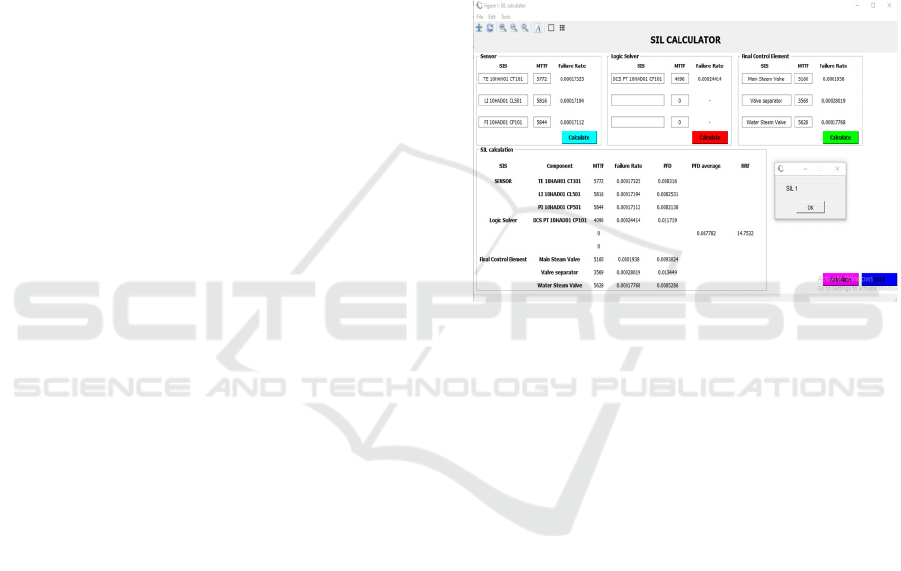
3.6 SIL Calculator Octave
This study uses octave software to perform
calculations automatically and determine the steam
drum's level of safety.
Figure 2: Sil Calculator.
To determine the value at the safety level for the
component, first, fill in the MTTF value for each SIS
and then calculate. Then the value from the
calculation will be called back to the SIL calculation.
If all the values are fulfilled, then by pressing the
calculate push button below, it will automatically
determine the safety level on the component via the
message box.
4 CONCLUSIONS
Based on the data obtained and analyzed. The
following are the findings of this research as SIL 1
includes steam drum components with SIF sensors,
DCS, and Finale control features. The approach of
substituting the failure rate of a small component in
SIL calculations, notably by changing the TI value
(time interval) and can also design a re-architecture
of the Steam drum system, is one way to raise the
level of safety. and the use of the SIL calculator
makes it easier to analyze the value of safety on
components
iCAST-ES 2022 - International Conference on Applied Science and Technology on Engineering Science
282

REFERENCES
Syahnanda, A. W., Permatasari, P. D., & Prasetya, H. E. G.
(2021, September). Design of Steam Power Plant
Condenser Machine Maintenance Using RCM
(Reliability Centered Maintenance) Methods with
RCPS Implementation. In 2021 International
Electronics Symposium (IES) (pp. 458-463). IEEE.
Faqih, M., Arini, N. R., & Prasetya, H. E. G. (2021). The
Development of A Reliability Evaluation Application
for Power Plant Steam Turbine Vibrations to Predict Its
Failure. EMITTER International Journal of
Engineering Technology, 9(2), 268-282.
Muqauwim, M. F., Prasetya, H. E. G., & Nurisma, R. A.
(2020, September). Analysis of Optimal Maintenance
Interval on ID Fan Using Reliability Centered
Maintenance. In 2020 International Electronics
Symposium (IES) (pp. 48-53). IEEE.
Rahmania, W. S., Prasetya, H. E. G., & Sholihah, F. H.
(2020, September). Maintenance Analysis of Boiler
Feed Pump Turbine Using Failure Mode Effect
Analysis (FMEA) Methods. In 2020 International
Electronics Symposium (IES) (pp. 54-59). IEEE.
Eliza Marceliana Zeinda, (2017) Sho’im Hidayat, “risk
assessment kecelakaan kerja pada pengoperasian boiler
di pt. indonesia power unit pembangkitan semarang”,
Vimalasari, T. (2016). Hazard And Operability Study
(HAZOP) Dan Penentuan Safety Integrity Level (SIL)
Pada Boiler SB-02 PT. Smart Tbk Surabaya (Doctoral
dissertation, Institut Teknologi Sepuluh Nopember).
Musyafa’, A., Nuzula, Z. F., & Asy’ari, M. K. (2019,
March). Hazop evaluation and safety integrity level
(SIL) analysis on steam system in ammonia plant
Petrokimia Gresik Ltd. In AIP Conference Proceedings
(Vol. 2088, No. 1, p. 020029). AIP Publishing LLC.
Nur, M. (2019). Usulan Perbaikan Sistem Manajemen
Keselamatan dan Kesehatan Kerja (SMK3) sebagai
Upaya Meminimalisir Angka Kecelakaan Kerja
Menggunakan Metode HAZOP (Studi Kasus: PT.
XYZ). SPECTA Journal of Technology, 3(3), 1-10.
Fitrani Kamila (2016) Penentuan Safety Integrity Level
Dengan Menggunakan Metode Layer of Protection
Analysis Pada Floating Regasification Unit
Safety Integrated Level Analysis and Risk Management in Steam Drum Based on the Octave Software
283
