Analysis of Stability on the ERISA Humanoid Dance Robot
Bianca Surya Nobelia, Novian Fajar Satria, Eko Henfri Binugroho and Teuku Zikri Fatahillah
Politeknik Elektronika Negeri Surabaya, Jl. Raya ITS, Kampus PENS, Surabaya, Indonesia
Keywords: Humanoid Robot, Kinematics, ERISA, IMU Sensor, Analysis of Stability, Center of Mass.
Abstract: ERISA is a humanoid robot dancing developed by PENS students to participate in Indonesia Robot Contest
(KRI) on the humanoid dancing robot division. One of the main assessments in this contest is to keep the
robot stable until the finish zone. To analyze the stability of a humanoid robot, the Inertial Measurement Unit
(IMU) sensor namely GY-952 is applied to detect the slope of the robot body. To determine the stability
analysis variable of the robot, the Ground Projection of Center of Mass (GCoM) method is used by using the
simplification of the Five Link Models. the ERISA robot starts to fall if there is an error approach around ±
40 mm. For future work, it is possible to apply it as feedback for a balance control system.
1 INTRODUCTION
The Indonesia robot contest has been held annually
for more than a decade, one of the divisions in that
contest is the Indonesia Dance Robot Contest
(KRSTI). KRSTI is a competition for designing,
manufacturing, and programming robots
accompanied by elements of Indonesian art and
culture, especially traditional dance in Indonesia. The
purpose of this robot contest is to cultivate the
students’ creativity and interest in technological
advances, especially in the industrial robotic field and
traditional dance culture (KRI Committe, 2021).
One of the main assessments in this contest is to
keep the robot stable until the finish zone. The
difficult part is to keep the balance of the robot while
performing dance movements and walking
simultaneously. To overcome this, it is necessary to
know about parameters of the stability of the robot
before build a balancing system. Many studies were
already conducted in this area, but in this paper
present one of the easiest ways to analyze the stability
of biped humanoid robotics by using an IMU sensor
with a simplified Five-links model method. In order
to prove this approach, the system was tested in three
different conditions.
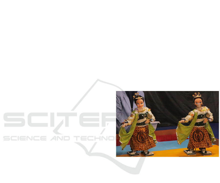
1.1 ERISA Robot Construction
The ERISA robot is designed using 29 servo motors
arranged on an aluminum frame, PLA+, and using an
ARM-type microcontroller as the main control
Figure 1: ERISA Robot Performance in KRSTI 2021.
system (Alasiry, Satria, & Sugiarto, 2018). The detail
of the construction is explained below.
1.1.1 Mechanical Structure
ERISA robot design has 29 DoF (Degree of Freedom)
consist of legs, body, hands, and head, as shown in
Table 1 (Alasiry, Satria, & Sugiarto, 2018). Figure 3
shows the isometric view of the mechanical skeleton
construction of the ERISA robot. Mechanical design
has been done by using Autodesk Inventor® software
and then the process of manufacturing parts is using
CNC machines and a 3D Printer.
182
Nobelia, B., Satria, N., Binugroho, E. and Fatahillah, T.
Analysis of Stability on the ERISA Humanoid Dance Robot.
DOI: 10.5220/0011738400003575
In Proceedings of the 5th International Conference on Applied Science and Technology on Engineering Science (iCAST-ES 2022), pages 182-187
ISBN: 978-989-758-619-4; ISSN: 2975-8246
Copyright © 2023 by SCITEPRESS – Science and Technology Publications, Lda. Under CC license (CC BY-NC-ND 4.0)
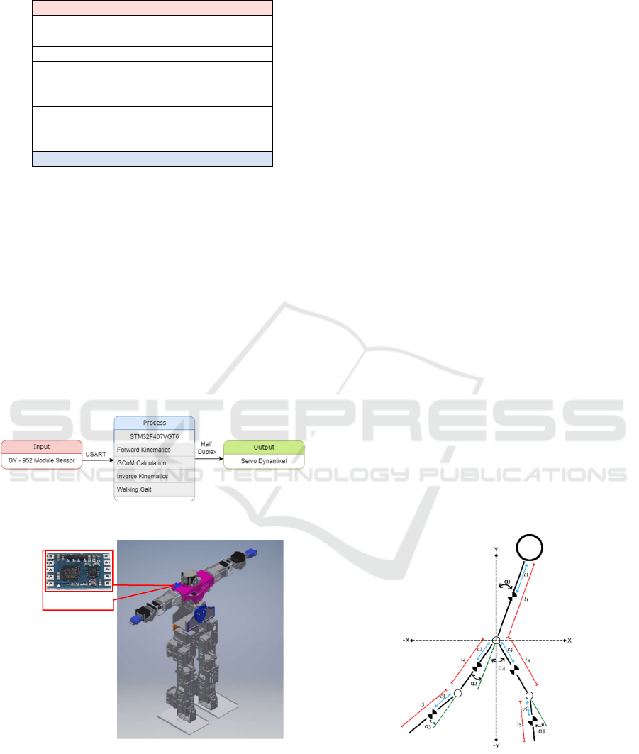
Table 1: DoF Part Detail on ERISA Robot.
No. Bod
y
Part Amount of DoF
1. Hea
d
3
(
Neck
)
2. Stomach 1
(
Stomach
)
3. Waist 1 (Waist)
4. Hand
6 (Shoulder)
2 (Elbow)
4 (Wrist)
5. Feet
6 (Hip)
2 (Knee)
4 (Ankle)
Total 29 DoF
1.1.2 Electrical Design
To control the overall performance, ERISA utilizes
STM32F407VGT as a microcontroller, it has a clock
frequency up to 168MHz. The main controller runs
robot performance ranging from kinematics
calculations, accessing sensors, and communicating
with other devices, in addition to more details can be
seen in Figure 1. This microcontroller also performs
the computation of the IMU data to access the roll,
pitch, and yaw angle of the robot body (Alasiry,
Satria, & Sugiarto, 2018). The orientation data will be
received by the main microcontroller over UART
communication.
Figure 2: System Configuration Block Diagram.
Figure 3: IMU Sensor Installation in the Robot Body.
1.1.3 IMU Sensor
The GY-952 module shown in Figure 3 is utilized as
the IMU sensor in this research. The GY-952 module
has a request-response communication model, so to
get the tilt data, the microcontroller must send a
request command over UART communication and
then wait for the response data. The microcontroller
needs to parsing of the data packets that have been
sent by the GY-952 module sensor. The placement of
the IMU sensor is on the shoulder of the robot,
because the shoulder of the robot is still in one
connection with the trunk link of the robot.
2 SYSTEM OVERVIEW
There are two types of kinematics applied to the
ERISA robot: forward kinematics and inverse
kinematics. The forward kinematics is applied to
control the movement of the hand servo and inverse
kinematics for the leg. The forward kinematics is also
used to enumerate the GCoM estimation.
2.1 Forward Kinematics
In general, forward kinematics is applied to find the
End of Effector (EoE) position when all of the angle
values in every joint are given. In this research,
forward kinematics explanation will be focused to
enumerate the GCoM estimation on the sagittal plane.
The humanoid robot model is simplified to a Five-
links model (Haavisto & Hyötyniemi, 2004) based on
the link that has the most dominant mass. The
humanoid Five-links model is shown in the following
figure. The value of 𝛼
1
will be obtained from IMU
sensor. While 𝛼
2
, 𝛼
3
, 𝛼
4
, 𝛼
5
are the current angle of
the servo.
Figure 4: The Five-Links Model.
𝑝𝑥
1
= 𝑙
1
× sin(𝛼
1
)
(1)
𝑝𝑥
2
= 𝑙
2
× sin(𝛼
1
+ 𝜋 + 𝛼
2
)
(2)
𝑝𝑥
3
= 𝑝𝑥
2
+ 𝑙
3
× sin(𝛼
1
+ 𝜋 + 𝛼
2
+ 𝛼
3
)
(3)
𝑝𝑥
4
= 𝑙
4
× sin(𝛼
1
+ 𝜋 + 𝛼
4
)
(4)
GY-952
Analysis of Stability on the ERISA Humanoid Dance Robot
183
𝑝𝑥
5
= 𝑝𝑥
4
+ 𝑙
5
× sin(𝛼
1
+ 𝜋 + 𝛼
4
+ 𝛼
5
)
(5)
𝑝𝑦
1
= 𝑙
1
× cos(𝛼
1
)
(6)
𝑝𝑦
2
= 𝑙
2
× cos(𝛼
1
+ 𝜋 + 𝛼
2
)
(7)
𝑝𝑦
3
= 𝑝𝑦
2
+ 𝑙
3
× cos(𝛼
1
+ 𝜋 + 𝛼
2
+ 𝛼
3
)
(8)
𝑝𝑦
4
= 𝑙
4
× cos(𝛼
1
+ 𝜋 + 𝛼
4
)
(9)
𝑝𝑦
5
= 𝑝𝑦
4
+ 𝑙
5
× cos(𝛼
1
+ 𝜋 + 𝛼
4
+ 𝛼
5
)
(10)
Where :
𝑙
𝑖
:
Length of i
th
link
𝛼
𝑖
:
Joint angle of i
th
link
𝑐
𝑖
:
CoM position of i
th
link
𝑝𝑥
𝑖
:
EoE position of i
th
link in X axis
𝑝𝑦
𝑖
:
EoE position of i
th
link in Y axis
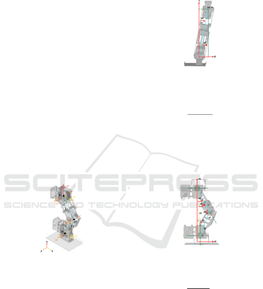
2.2 Inverse Kinematics
The Inverse Kinemtics used to resolve the walking
trajectory in 3-Dimensional cartesian form. This
inverse kinematic system is modeled on 6 DoF for
each robot's leg, where the hip is managed as the base
and the ankle as the End of Effector. The modeling
calculation applies the triangle geometry solution.
Cartesian coordinates are symbolized by the (x, y, z)
axis, and for joints symbolized by the (α
1
, α
2
, α
3
, α
4
,
α
5
, α
6
) degree. Figure 5 has illustrated the isometric
shape of the robot leg configuration.
Figure 5: Joint Configuration on the Robot Leg (isometric
view).
𝛼
1
= 𝜃
𝐻
(11)
𝑅
0 =
√
𝑋
2
+
𝑍
2
Where :
𝜃
𝐻
= Heading direction
𝑅0 = Resultant between X and Z value
As shown in Figure 5, joint 1 is directly affected by
the heading direction.
Figure 6: Kinematics Model in Front View.
𝛽
=tan
−1
(
𝑍
∕
X
)
–
α1
𝑠𝑍 = 𝑍 +
(
𝑅0 × sin 𝛽
)
𝑠𝑋 = 𝑋 −
(
𝑅0 × cos 𝛽
)
𝛼
2
= tan
−1
(
𝑠𝑍
∕
𝛾
)
(12)
Where :
𝛽 = Distance between R0 and sX
𝑠𝑍 = Distance that occurs due to the angle 𝛽
𝑠𝑋 = Length of the hypotenuse of the triangles R0
and sZ
𝛼
2
= Angle between sZ and 𝛾
𝑅1 = Resultant between sZ and 𝛾
Figure 7: Kinematics Model in Side View.
The joint angle 2 can be obtained by referring to Figur
6. Where joint 2 is a plane that shows the side view,
so that the robot's legs look like human legs.
𝛼
3
= 0 − 𝛾𝐴 + 𝛾𝐵
(13)
𝛼
4
= 180 − 𝛾𝐶
(14)
𝛼
5
=
𝛼
3
−
𝛼
4
(15)
𝛼
6
= 0 −
(
𝛾𝐴 + 𝛾𝐵
)
(16)
𝑅1
𝛾
2
𝑠𝑍
2
𝑅2
𝑅1
2
𝑠𝑋
2
𝛾𝐶 cos
1
𝐿1
2
𝐿2
2
𝑅2
2
2𝐿1𝐿2
𝛾𝐴 sin
1
𝑋
𝑅2
𝛾𝐵 sin
1
𝐿2 sin𝛾𝐶
𝑅2
iCAST-ES 2022 - International Conference on Applied Science and Technology on Engineering Science
184
Where :
𝐿1 = Length of the upper leg
𝐿2 = Length of the lower leg
R2 = Resultant between the R1 and sX
𝛾𝐴 = Angle between R2 and R1
𝛾B = Angle between R2 and L1
𝛾C = Angle between L1 and L2x
𝛼
3
= Angle from the sum of 𝛾𝐴 and 𝛾B
𝛼
4
= Angle of subtraction 180° and 𝛾C
𝛼
5
= Angle of the sum of 𝛼
3
and 𝛼
4
𝛼
6
= Reflection from angle 𝛼
2
After getting the values required for the calculations
in Figure 5, another joint angle can be computed.
From the inverse kinematics explanation above, eight
coordinate data are acquired for moving the robot's
legs, namely x, y, z, and headings, for the right foot
and left foot, respectively (Alamri, 2020).
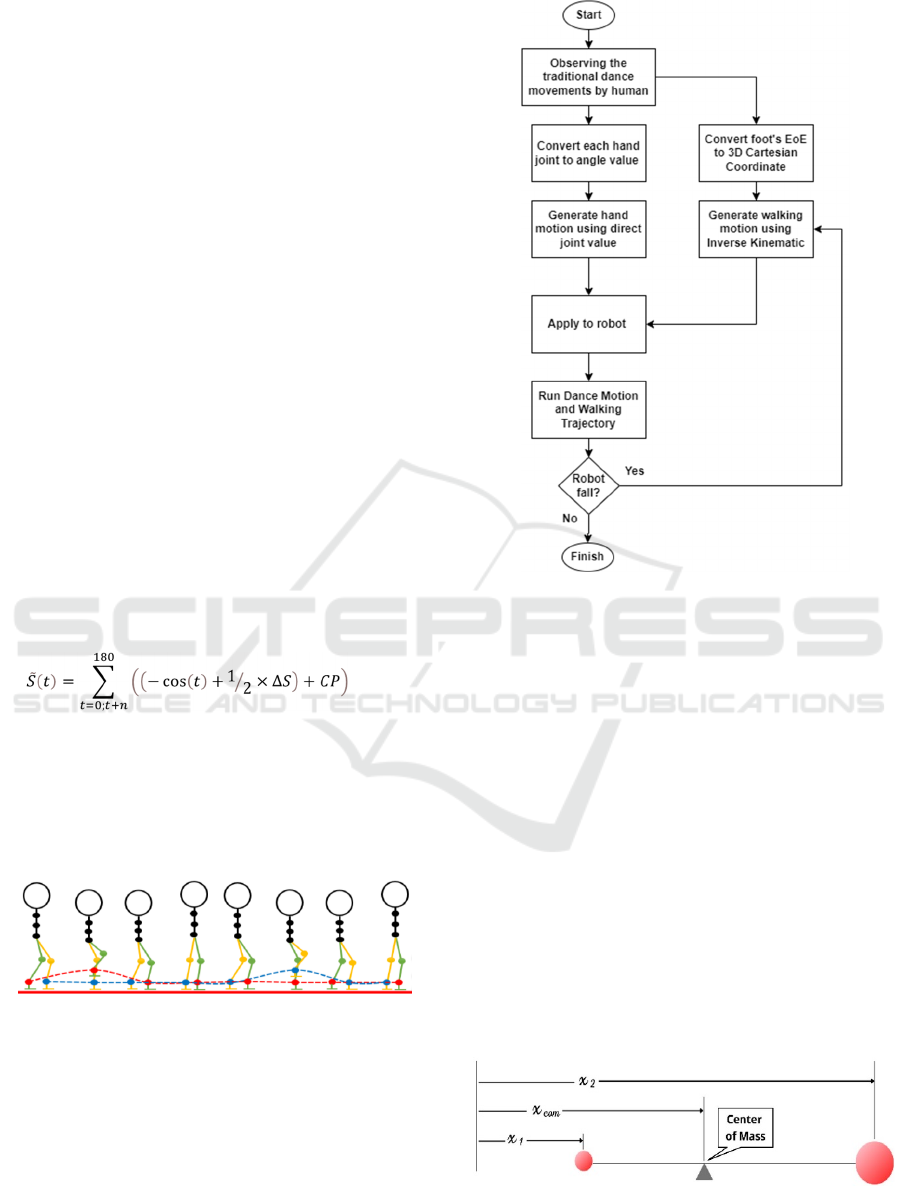
2.3 Walking Gait
This system utilizes a parabolic function trajectory
pattern algorithm (walking path) with a set time
interval, where the time interval is a parameter that
can be changed (Alamri, 2020). The following
trajectory equation is shown in equations (17) and
(18).
∆S = PP − CP
(17)
(18)
Where :
∆S = Difference between start and end positions
PP = Previous Positions
CP = Current Positions
θ = Time Interval
= Output position at time (t)
Figure 8: Inverse Kinematics of ERISA Robot.
The gait trajectory applied by ERISA to perform its
walking sequence is 8 steps shown in Figure 8. The
red color represents the right leg, while the blue color
represents the left leg (Rahmawati, et al., 2021).
2.4 Motion Choreography
The dancing motion applied to the robot still uses trial
and error tuning, as shown in the following flowchart.
Figure 9: ERISA Robot’s Tuning Method Flowchart.
Because the ERISA robot is still using an open-loop
system, that’s why when the robot falls, the walking
trajectory must be corrected manually.
2.5 Ground Projection Center of Mass
(GCoM)
The Center of Mass (CoM) is the point where the
average mass of an object is equal to zero. All
external forces and momentum will have an effect on
the CoM of an object. Therefore in humanoid robots,
CoM is utilized as a reference point to see the slope
of the robot due to the force and momentum that
occurs, which can be used as the error value
(Nugroho, 2014). To keep the robot in balance the
Ground Projection of the Center of Mass (GCoM)
must be kept strictly inside the support polygon
(Goswami, 1999).
Figure 10: Center of Mass.
𝑆
(t)
Analysis of Stability on the ERISA Humanoid Dance Robot
185
𝑥
1
= 𝑐
1
× sin(𝛼
1
)
𝑥
2
= 𝑐
2
× sin(𝛼
1
+ 𝜋 + 𝛼
2
)
𝑥
3
= 𝑝𝑥
2
+ 𝑐
3
× sin(𝛼
1
+ 𝜋 + 𝛼
2
+ 𝛼
3
)
𝑥
4
= 𝑐
4
× sin(𝛼
1
+ 𝜋 + 𝛼
4
)
𝑥
5
= 𝑝𝑥
4
+ 𝑐
5
× sin(𝛼
1
+ 𝜋 + 𝛼
4
+ 𝛼
5
)
Where :
𝑚
𝑖
:
Mass of i
th
link
𝑥
𝑖
:
GCoM position of i
th
link in X-axis
3 RESULT
To analyze the stability of the robot using GCoM
estimation, there are three different conditions
applied to the robot, first is tracking GCoM position
while the robot dancing and walking, second is while
the robot dancing and doing one leg lifting motion,
third is while the robot dancing and walking on
obstacle. The data is taken by following the sequence
as shown below.
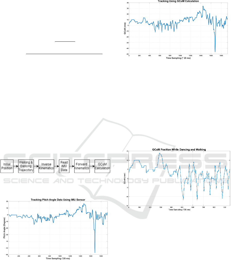
Figure 11: System Design.
3.1 Tracking GCoM Position
Figure 12: Tracking Pitch Angle Data using IMU Sensor.
Figure 13: Tracking GCoM Position.
Figure 12 and Figure 13 are a comparison between
tracking pitch data from the IMU sensor and tracking
the GCoM position. The most basic difference occurs
in GCoM calculation with Five-links model engaging
the consideration while doing leg motion, whereas
tracking pitch angle only uses data from the IMU
sensor. There is a moment when the robot's posture is
detected as an error, but it is still considered balanced
based on its GCoM value. And vice versa, there is a
moment when the robot's posture is detected as
balanced by the IMU, but the motions can cause the
robot to be unbalanced.
Figure 14: Graph of Tracking GCoM Position While the
Robot Dancing and Walking.
Figure 14 unveils the experimental result while doing
dance motions and walking. From the data above, the
magnitude of the GCoM error with the reference (0
mm) make a fluctuation, which is up to 10 mm and
less than -10 mm. This would cause the robot in an
unstable condition.
𝐺𝐶𝑜𝑀
∑
𝑛
𝑖1
𝑚
𝑖
𝑥
𝑖
∑
𝑛
𝑖
1
𝑚
𝑖
𝐺𝐶𝑜𝑀
𝑚
1
𝑥
1
𝑚
2
𝑥
2
𝑚
3
𝑥
3
𝑚
4
𝑥
4
𝑚
5
𝑥
5
𝑚
1
𝑚
2
𝑚
3
𝑚
4
𝑚
5
iCAST-ES 2022 - International Conference on Applied Science and Technology on Engineering Science
186
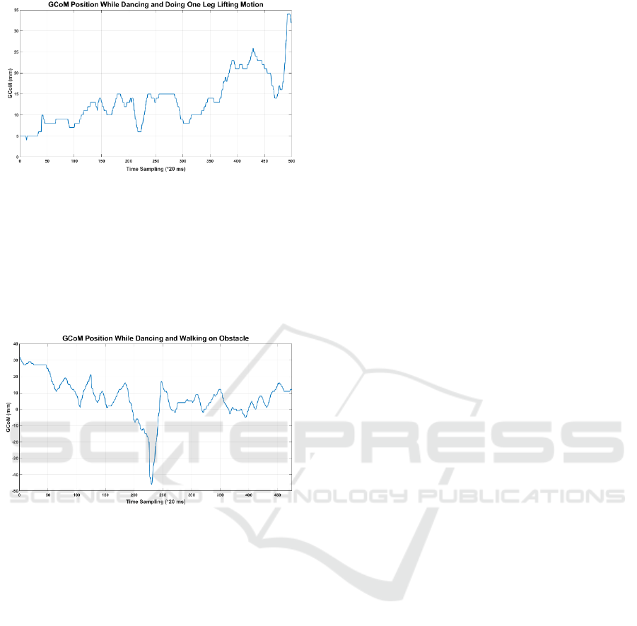
Figure 15: Graph of Tracking GCoM Position While the
Robot Dancing and Doing One Leg Lifting Motion.
From the second condition, it can be inferred that
carrying out one leg lifting motion will also cause the
robot's body to be unstable. Although the GCoM error
of the robot reaches 34 mm, it doesn’t cause the robot
fall. However, this situation make the robot easier to
fall if there is any other disturbance.
Figure 16: Graph of Tracking GCoM Position While the
Robot Dancing and Walking on Obstacle.
Figure 16 shows that walking on the obstacle will
cause the robot to fall backwards with a GCoM error
around -40 mm. In other word, if the error value
reaches approximately ± 40 mm, the robot no longer
maintain its stability.
4 CONCLUSIONS
This study reveals one method to analyze the stability
of a humanoid robot, which is by computing the
position of the Center of Mass projected directly to
the ground using a Five-links model. Calculating
GCoM has more advantage than only using the angle
value obtained from the IMU sensor, because it does
not only consider the tilt of the robot's posture, but
also the movements performed. Based on the
experiments, the ERISA robot began to fall when the
GCoM error reached the range of ± 40 mm. For future
works, it is possible to apply this analysis as feedback
for balance control.
ACKNOWLEDGMENTS
This research is supported by the ERISA robotics
team and Industrial Robotic Laboratory at Politeknik
Elektronika Negeri Surabaya (PENS) (Rahmawati, et
al., 2021).
REFERENCES
Alamri, R. D. (2020). Kontrol Keseimbangan Robot
Humanoid ERISA Menggunakan PID Dengan Sensor
Fusion. Surabaya: Politeknik Elektronika Negeri
Surabaya.
Alasiry, A. H., Satria, N. F., & Sugiarto, A. (2018). Balance
Control of Humanoid Dancing Robot ERISA while
Walking on Sloped Surface using PID. International
Seminar on Research of Information Technology and
Intelligent Systems (ISRITI) (hal. 577-581).
Yogyakarta: IEEE.
Goswami, A. (1999). Postural Stability of Biped Robots
and the Foot-Rotation Indicator (FRI) Point. The
International Journal of Robotics Research, 523-533.
Haavisto, O., & Hyötyniemi, H. (2004). Simulation tool of
a biped walking robot model. Helsinki: Helsinki
University of Technology.
KRI Committe. (2021). Buku 5 Kontes Robot Seni Tari
Indonesia (KRSTI) Daring 2021. Petunjuk
Pelaksanaan Kontes Robot Indonesia (hal. 65-78).
Jakarta: Pusat Prestasi Nasional Kementerian
Pendidikan RI.
Nugroho, A. T. (2014). Optimalisasi Pergerakan dan
Algoritma Robot Humanoid Sebagai Kiper. Salatiga:
Universitas Kristen Satya Wacana.
Rahmawati, M. S., Irwansyah, A., Binugroho, E. H.,
Alasiry, A. H., Satria, N. F., & Basuki, D. K. (2021).
ERISA Robot’s Walking Trajectory Control using Pixy
CMUcam5 to Locate the Target Position. International
Electronics Symposium (IES) (hal. 476-481). Surabaya:
IEEE.
Analysis of Stability on the ERISA Humanoid Dance Robot
187
