
Analysis of the Effect of Double Waste Valves in Series Arrangement
and Compressor Tube Layout on the Performance Efficiency of
2 Inch Hydraulic Ram Pump
Rafael Mado, Alexius Leonardo Johanis, Frans Mangngi and Irene Budayawati
Mechanical Engineering Department, State Polytechnic of Kupang, Lasiana, Kupang, Indonesia
Keywords: Hydraulic Ram Pump, Layout, Double Waste Valve, Efficiency, Performance, Series Arrangement.
Abstract: Water is an absolute necessity for the survival of life because without water there will be no life in this
world. For areas that are close to water sources or are located close to springs, the need for water is not a
problem. The laws of physics say that water flows from a higher place to a lower place, but the fact is that
the land surface is not always flat; there are hilly and bumpy areas. For areas that are higher than the water
source, it will be difficult to get a continuous supply of water. One of the efforts to get water supply for
areas that are higher than the spring is to use a water pump. The types of pumps commonly used today are
electric-powered water pumps and fuel-powered water pumps. In urban areas, the need for fuel and
electricity is not a problem, but in rural areas, the availability of fuel and electricity is very scarce and
expensive. The hydraulic ram is the answer to this problem. One of the efforts to increase the efficiency of
hydraulic ram pump performance is by increasing the number of waste valves arranged in series. The
problem is, is there any effect of the arrangement of the double waste valve series on the performance
efficiency of the 2-inch hydraulic ram pump at the Input-Compressor-Waste-Waste (ICWW) position, the
Input-Waste-Waste-Compressor (IWWC) position, and the Input-Waste-Compressor-Waste position.
(IWCW)? The purpose of this research is to design, manufacture, and test the arrangement of the double
valve series of hydraulic ram pumps at three different positions (ICWW, IWWC, and IWCW) using a 3000
ml compressor tube. So, it could be seen the optimal performance efficiency of the hydraulic ram pump.
The method used is a site survey, literature study, and action method with the design of the hydraulic ram
pump installation, as well as observing the effect of using a double exhaust valve in series at the ICWW,
IWWC, and IWCW positions on the efficiency of the 2-inch hydraulic ram pump performance. The results
of this study indicate that the largest pumping discharge occurs in the IWCW pump arrangement (Input-
Waste-Compressor-Waste) with a waste valve weight of 367 grams; at input 180 liters/minute produces
output 0.131 liters/second and at input 170 liters/minute produces output 0.107 liters/second. The greatest
efficiency also occurs in the IWCW pump arrangement (Input-Waste-Compressor-Waste) with a waste
valve weight of 367 grams; at the input of 180 lt/min by 132% and at the input of 170 lt/min by 110%
(according to D'Aubuison Efficiency).
1 INTRODUCTION
Water is an absolute necessity for the survival of
life, because without water there will be no life in
this world. Especially for areas that are close to
water sources or are located under springs, water
demand is not too much of a problem. Areas where
the land surface is higher than the water source will
have difficulty getting a continuous water supply.
One of the efforts to meet water needs, especially
in locations higher than the springs, is to use a water
pump. The type of pump that is commonly used
today is a water pump powered by an electric motor
or a fuel oil engine which is difficult to obtain in
remote rural areas. The solution is to use a hydraulic
ram pump, because a hydraulic ram pump works
without the use of fuel or electricity.
The problem is whether to increase the number
of waste valves (double waste valves) arranged in
series at the Input-Waste-Waste-Compressor
(IWWC), Input-Compressor-Waste-Waste (ICWW)
and Input-Waste-Compressor-Waste (IWCW)
positions. , can increase the efficiency of the 2 inch
hydram pump performance.
158
Mado, R., Johanis, A., Mangngi, F. and Budayawati, I.
Analysis of the Effect of Double Waste Valves in Series Arrangement and Compressor Tube Layout on the Performance Efficiency of 2 Inch Hydraulic Ram Pump.
DOI: 10.5220/0011729800003575
In Proceedings of the 5th International Conference on Applied Science and Technology on Engineering Science (iCAST-ES 2022), pages 158-163
ISBN: 978-989-758-619-4; ISSN: 2975-8246
Copyright © 2023 by SCITEPRESS – Science and Technology Publications, Lda. Under CC license (CC BY-NC-ND 4.0)
Various studies have been carried out in an effort
to improve the efficiency of the hydraulic ram pump
performance, such as (Asep Supriyanto et al., 2017)
conducted a study entitled “Pengaruh Variasi Jarak
Sumbuh Katub Limbah dengan Sumbuh Tabung
Udara Terhadap Efisiensi Pompa Hidram”, in which
the results showed that the variation of the shortest
distance (0.25 m) get an output discharge of 0.0041
m³/second with an efficiency of 14%.
(Aris Eko Sulistiawan, et al., 2006), also
conducted a study entitled “Pengaruh Berat Katub
Limbah dan Ketinggian Discharge Terhadap Kerja
Pompa Hidram”. The results showed that, the best
capacity at the west of the waste valve is 200 grams
with a value of 7.75 liters/minute at 3 meters
discharge, volumetric efficiency is 52.961% and
pump efficiency is 60.623%.
Another study conducted by (Muhamad Jafri et
al., 2017), entitled “Analisa Beda Tinggi Katub
Limbah dan Variasi Diameter Pipa Inlet Terhadap
Unjuk Kerja Pompa Hidram Ukuran Dua Inchi”.
The results showed that the minimum efficiency of
59.15% was obtained at a valve height difference of
15 cm and an inlet pipe diameter of 3 inches, while
the highest efficiency was obtained at 95.29% at a
different valve height of 10 cm and an inlet pipe
diameter of 2 inches.
(Muhamad Fajri et al., 2015), also conducted a
study entitled “Pengaruh Diameter Katub Limbah
dan Jarak Antara Katub Limbah dengan Katub
Penghantar Terhadap Efisiensi Pompa Hidram. The
results showed that the highest efficiency obtained
was 79.7535% at a waste valve diameter of 0.041
meters and a distance between valves of 0.130
meters.
From previous studies, no researcher has raised
the issue of the number of waste valves used in
increasing the efficiency of hydraulic ram pump
performance.
The purpose of this study was to design and
manufacture a hydraulic ram pump and to test the
use of a double valve in series arrangement in three
positions: Input-Waste-Waste-Compressor (IWWC),
Input-Compressor-Waste-Waste (ICWW) and Input-
Waste-Compressor-Waste (IWCW).
The main issue that will be raised in this research
is the use of new and renewable energy in meeting
the needs of clean water for rural communities,
especially those that have not been reached by the
State Electricity Company.
The results of this study are expected to solve the
problems mentioned above, so that people can take
advantage of the natural resources that are around
them (river water), for their daily needs such as
drinking water, watering plants and giving water to
their livestock. Thus the standard of living of the
people will be better.
2 RESEARCH METHOD
2.1 Design and Manufacture of 2 Inch
Ram Hydraulic Pump with Double
Drain Valve Series Arrangement
The hydraulic ram pump is designed with an input
pipe diameter of 2” or 5.075 cm, an output pipe
diameter of 1.27 cm, a compressor tube volume of
3000 ml, with variations in the arrangement of
ICWW, IWWC and IWCW. The inclination angle of
the inlet pipe is 5
0
, water drop height is 1.5 meters,
and water lift height is 5 meters. The hydraulic ram
pump is made using iron pipe (T shock) ø 2 inch,
double nipple 2 inch, elbow 2 inch, elbow inch, steel
pipe ø 2½ inch, elbow iron 70x70x6000 mm, solid
stainless ø 10 mm, steel axle ø 40 mm , paralon pipe
ø 2 inch and ½ inch, 5 mm thick rubber, bolts and
nuts. The results of the design of the hydraulic ram
pump as shown in Figures 1, 2 and 3 below:
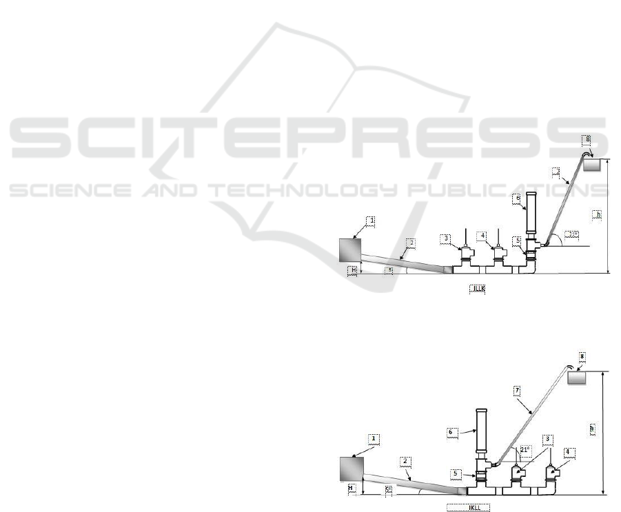
Figure 1: Installation of Hydraulic Ram Pump in IWWC
Arrangement.
Figure 2: Installation of Hydraulic Ram Pump in ICWW
Arrangement.
Analysis of the Effect of Double Waste Valves in Series Arrangement and Compressor Tube Layout on the Performance Efficiency of 2 Inch
Hydraulic Ram Pump
159
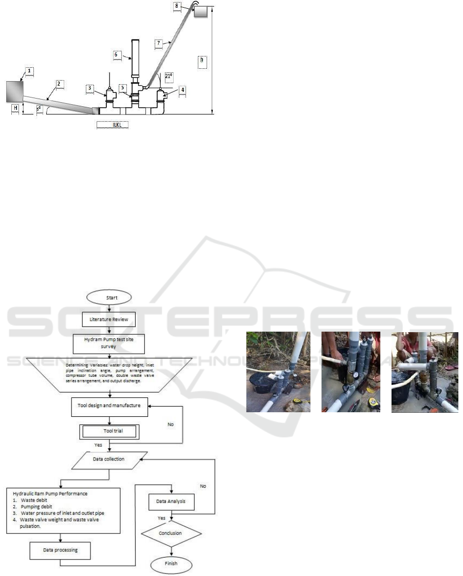
Figure 3: Installation of Hydraulic Ram Pump in IWCW
Arrangement.
Image Captions:
1. Water source 5. Delivery valve
2. Inlet pipe 6. Compressor tube
3. Waste valve (1) 7. Exhaust pipe
4. Waste valve (2) 8. Reservoir
H = Height of fall
h = Lift height
2.2 Research Flowchart
Figure 4: Flowchart of this system.
2.3 Data Collection Method
The method used is experimental method with 10
independent variables. They are the water fall height
(H) 1.5 m, lift height (h) 5 m with a slope of 21,72
0
following the contour of the ground and the length
of the outlet pipe is 13.60 m, the slope angle of the
slide pipe (5
0
) with a slide pipe length of 17.24 m,
water flow entering the pump (180 and 170
liters/min), IWWC position, ICWW position,
IWCW position, compressor tube volume 3000 ml.
While the 7 dependent variables are: sewage
discharge (Q), inlet water pressure, outlet pressure,
pumping discharge (q), waste valve weight, waste
valve pulse and hydraulic ram pump efficiency
(calculated using equation 1).
Prior to testing and data collection, the water
drop height (H) was conditioned at least 1.5 m with
the discharge water being 180 liters/minute and 170
liters/minute. The test will be carried out 18 times in
accordance with 3 variations of the compressor tube
position (IWWC, ICWW, IWCW) and 3 variations
of the weight of the waste valve (367 grams, 567
grams, 695 grams) both at intake discharge of 180
liters/minute and 170 liters/minute. Each test will be
recorded carefully in the data table that has been
prepared.
(a) IWWC
(b) ICWW
(c) IWCW
Figure 5: Schematic of the hydraulic ram pump test
installation.
In testing the researcher used supporting
equipment such as a measuring cup, a bucket, seal
tapes, PVC glue, machete, shovel, roller meter,
pressure gauge, water fitting, nylon ropes, bamboo,
pipe wrench, and a stopwatch. Data retrieval is done
by reading the pressure on the pump inlet pipe,
pressure on the outlet pipe, measuring the pulse of
the waste valve, measuring the discharge of the
waste and the discharge of the pumping.
2.4 Data Processing Method
The data that has been collected in tabular form will
be made in graphical form to obtain the relationship
between variations in the position of the compressor
iCAST-ES 2022 - International Conference on Applied Science and Technology on Engineering Science
160
tube, variations in the weight of the waste valve, and
the pulse of the waste valve to the pumping
discharge.
The hydraulic ram pump efficiency can be
calculated in two ways:
According to D’Aubuisson (Murni, 2016)
η =
𝑞
(
𝐻+ℎ
)
(𝑄+𝑞)
...................................... (1)
According to Rankine :
η =
𝑞.ℎ
𝑄.𝐻
………………………… (2)
Where: η = hydraulic ram pump
efficiency (%)
q = result (m
3
/det.)
Q = waste (m
3
/det.)
h = head out (m)
H = head in (m)
3 RESULT AND DISCUSSION
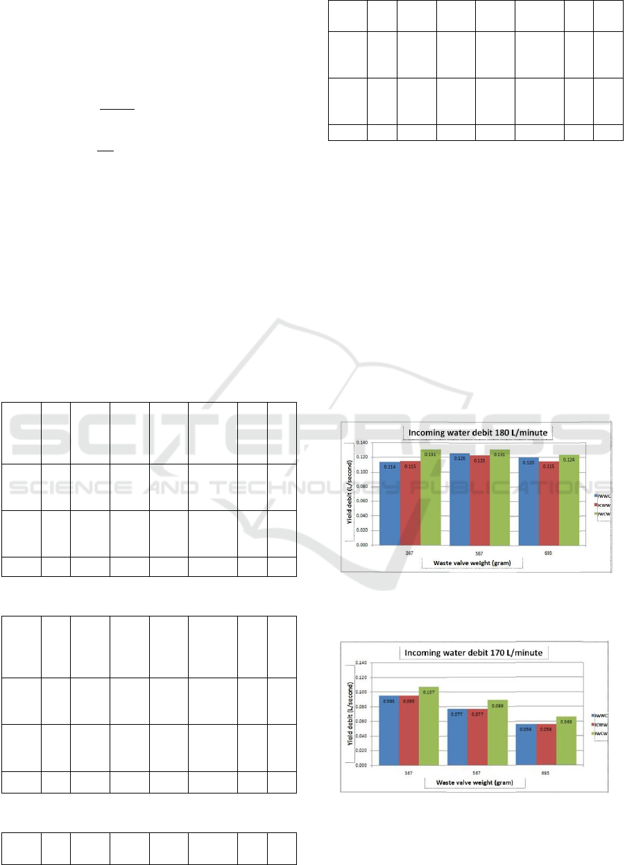
The test result data can be seen in Tables 1, 2 and 3
below:
Table 1: Position of IWWC.
Incoming
debit
(L/minute)
Waste
valve
weight
(gram)
Waste
valve
pulsation
(x/minute)
Waste
debit Q
(L/second)
Yield
debit Q
(L/second)
D’Aubuison
Efficiency
ɳ (%)
Pump
inlet
pressure
(bar)
Pump
outlet
pressure
(bar)
180
367
567
695
36
28
26
0,495
0,679
0,800
0,114
0,126
0,120
122
102
85
0,6
0,6
0,6
0,6
0,6
0,6
170
367
567
695
34
26
18
0,537
0,752
0,869
0,095
0,077
0,056
98
60
39
0,6
0,6
0,6
0,6
0,6
0,6
135
Tabel 2: Position of ICWW.
Incoming
debit
(L/minute)
Waste
valve
weight
(gram)
Waste
valve
pulsation
(x /minute)
Waste
debit Q
(L/second)
Yield
Debit Q
(L/second)
D’Aubuison
Efficiency
ɳ (%)
Pump
inlet
pressure
(bar)
Pump
outlet
pressure
(bar)
180
367
567
695
34
28
26
0,494
0,645
0,754
0,115
0,123
0,115
123
104
86
0,6
0,6
0,6
0,6
0,6
0,6
170
367
567
695
33
26
21
0,493
0,768
0,921
0,095
0,077
0,056
115
72
53
0,6
0,6
0,6
0,6
0,6
0,6
135
Tabel 3: Position of IWCW.
Incoming
debit
Waste
valve
Waste
valve
Waste
debit Q
Yield
Debit Q
D’Aubuison
Efficiency
Pump
inlet
Pump
outlet
(L/minute)
weight
(gram)
pulsation
(x /minute)
(L/second)
(L/second)
ɳ (%)
pressure
(bar)
pressure
(bar)
180
367
567
695
34
28
25
0,514
0,639
0,764
0,131
0,131
0,124
132
103
91
0,6
0,6
0,6
0,6
0,6
0,6
170
367
567
695
33
25
17
0,523
0,749
0,088
0,107
0,089
0,066
110
69
37
0,6
0,6
0,6
0,6
0,6
0,6
135
1
The results of the hydraulic ram pump test on the
layout of the compressor tube, Input-Waste-Waste-
Compressor (IWWC), Input-Compressor-Waste-
Waste (ICWW) and Input-Waste-Compressor-Waste
(IWCW) with 2 variations of intake discharge (180
liters) /minute 170 liters/minute) and 3 variations of
the weight of the waste valve, as shown in tables 4.1,
4.2 and 4.3 above. The relationship between the
weight of the waste valve and the output discharge
to the position of the compressor tube is presented in
Figure 5 (incoming flow rate of 180 liters/minute)
and Figure 6 (incoming flow rate of 170
liters/minute). The position of the IWCW
compressor tube shows a higher pumping discharge
compared to the position of the IWWC and ICWW
compressor tubes.
Figure 6: Comparison of the output discharge value with
the weight of the waste valve on the compressor tube
position.
Figure 7: Comparison of the output discharge value with
the weight of the waste valve on the compressor tube
position.
Analysis of the Effect of Double Waste Valves in Series Arrangement and Compressor Tube Layout on the Performance Efficiency of 2 Inch
Hydraulic Ram Pump
161
The most ideal waste valve weight is 567 grams
at the intake discharge of 180 liters/minute for the
three compressor tube positions (IWWC, ICWW and
IWCW), while at the intake discharge 170
liters/minute, the appropriate waste valve weight for
the three compressor tube positions is 367 grams
(see Figure 8), in which the weight of the waste
valve must be adjusted to the intake discharge.
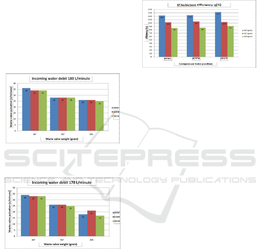
The effect of the weight of the waste valve on the
pulse of the waste valve and the position of the
compressor tube is presented in Figures 7 and 8,
where the heavier the waste valve, the slower the
pulse produced, both at the intake discharge of 180
liters/minute and 170 liters/minute.
Figure 8: Comparison of the value of the weight of the
waste valve with the pulse of the waste valve to the
position of the compressor tube (inlet discharge 180 liters /
minute).
Figure 9: Comparison of the value of the weight of the
waste valve with the pulse of the waste valve to the
position of the compressor tube (at the inlet 170
liters/minute).
The relationship of the waste valve pulse to the
pumping discharge at the hydraulic ram pump with
the arrangement of IWWC, ICWW and IWCW is
shown in Tables 1, 2 and 3, where the higher the
number of pulses, the higher the pumping discharge.
The efficiency of the hydraulic ram pump as a
comparison of the pumping discharge with the inlet
and effluent discharges as well as the ratio of the
weight of the waste valve and the output discharge
in each pump arrangement is presented in Figure 9
below.
Figure 10: Graph of the relationship between compressor
tube position and waste valve weight on D'Aubuisson
efficiency.
In general, the highest efficiency value is
obtained at the position of the IWCW compressor
tube (Input-Waste-Compressor-Waste), both at the
intake discharge of 180 liters/minute and 170
liters/minute with a waste valve weight of 367 grams
which is 132% and 110% (according to the
D'Aubuison efficiency).
The results of previous research using a single
waste valve, the highest efficiency obtained was
only 127% on the IWC hydraulic ram pump
arrangement. This means there is an increase in
efficiency by 5%.
The efficiency value obtained according to
D'Aubuisson looks greater than 100%, occurs at
every position of the compressor tube IWWC,
ICWW and IWCW. This is due to the large amount
of water entering the pump, which is 180
liters/minute (measurements before testing). In
addition, the slope angle of the inlet pipe is getting
smaller (50) so that the inlet pipe is getting longer
which affects the suction and thrust forces so that the
efficiency of the hydraulic ram pump is higher.
Research conducted by R. Sutanto (2019), also
shows that the smaller the plunge angle used, the
greater the output discharge generated, the greater
the plunge angle, the smaller the suction and thrust
forces of the hydraulic ram pump.
4 CONCLUSIONS
Based on the results of testing and data processing, it
can be concluded as follows:
a. The largest output/pumping discharge occurred
at the position of the IWCW (Input-Waste-
Compressor-Waste) compressor tube, both at the
iCAST-ES 2022 - International Conference on Applied Science and Technology on Engineering Science
162

intake discharge of 180 liters/minute and 170
liters/minute with a waste valve weight of 367
grams which were 0.131 liters/second and 0.107
liters. /second.
b. The greatest efficiency also occurs at the position
of the IWCW compressor tube (Input-Waste-
Kompresor-Waste), both at the intake discharge
of 180 liters/minute and 170 liters/minute with a
waste valve weight of 367 grams, which are
132% and 110% (according to the efficiency of
D 'Aubuison).
REFERENCES
Agus Prastyo. Analisa Pengaruh Dimensi Tabung Udara
Terhadap Prestasi Pompa Hidram Prototype, Jurusan
Teknik Mesin Fakultas Teknik Universitas
Muhammadyah Jember.
Aris Eko Setyawan, dkk. (2006). Pengaruh Berat Katub
Limbah dan Ketinggian Discharge Terhadap Kinerja
Pompa Hidram, Pendidikan Teknik Mesin, Fakultas
Teknik Universitas Negeri Surabaya.
Asep Supriyanto, dkk. (2017). Pengaruh Variasi Jarak
Sumbuh Katub Limbah Dengan Sumbuh Tabung
Udara Terhadap Efisiensi Pompa Hidram, Jurnal
Teknik Mesin Univ.Muhammadya Metro, TURBO
Vol. 6 No. 2.
I Gede Bawa Susama dan Rudy Susanto.(2016).
Peningkatan Kinerja Pompa Hidram Berdasarkan
Posisi Tabung Kompresor dengan Saluran Keluar di
bawah Tabung Kompresor, Jurnal Dinamika Teknik
Mesin 6.
Muhamad Fajri, dkk. (2015). Pengaruh Diameter Katub
Limbah dan Jarak antara Katub Limbah dengan Katub
Penghantar Terhadap Efisiensi Pompa Hidram, Jurnal
Teknik Mesin Undana, Vol. 02 No. 01.
Muhamad Jafri, dkk. (2017). Analisis Pompa Hidram 2
inchi dengan Sistim Kompresi Seri, Prosiding Seminar
Nasional Teknik FST-UNDANA .
Murni, dkk. (2016). Kaji Eksperimental Pengaruh
Ketinggian Permukaan Air Pompa Hidram Diameter
Inlet ¾ inch Dengan Sudut Kemiringan 15
0
Terhadap
Kinerja Pompa.
Rafael Mado, dkk. (2021). Pengaruh Tata Letak Rumah
Pompa dan Variasi Volume Tabung Kompresor
Terhadap Efisiensi Unjuk Kerja Pompa Hidram 2
Inch, Laporan Penelitian Terapan, Jurusan Teknik
Mesin Politeknik Negeri Kupang.
R. Sutanto, dkk. (2019). Variasi Sudut Pipa Masukan
Terhadap Unjuk Kerja Pompa Hydram, Jurnal
Keilmuan dan Terapan Teknik Mesin, Dinamika
Teknik Mesin 9 (1).
Teferi Taye. (1998). Hydraulic Ram Pumps, Journal of the
Ethiopian Society of Mechanical Engineers, Vol. II,
No. 1.
Toto Citramurti, dkk. (2015). Pengaruh Beban Katub
Buang di bawah 450 gram Menggunakan Panjang
Input 4 m dan Ketinggian Output 10 m terhadap
Kinerja Pompa Hidram, Jurnal Widya Teknika Vol. 23
No.1.
Widarto dan FX. Sudarto. (1997). Membuat Pompa
Hidram, Teknologi Tepat Guna, Penerbit Kanisius,
Jakarta.
Analysis of the Effect of Double Waste Valves in Series Arrangement and Compressor Tube Layout on the Performance Efficiency of 2 Inch
Hydraulic Ram Pump
163
