
Assessment of Passenger Comfort, Taking into Account Their
Position in the Cabin and the Design Features of the Car
A. S. Mitrakov
1
a
, D. Ya. Antipin
2
b
and V. F. Lapshin
1
c
1
Ural State University of Railway Transport, Ekaterinburg, Russia
2
Bryansk State Technical University, Bryansk, Russia
Keywords: Passenger car, flexible floor, mathematical modeling, passenger comfort, anthropometric dummy, unbalanced
acceleration, net dose of motion sickness.
Abstract: A method for predicting the comfort level of passengers in an electric train car is proposed, taking into account
the design features of the car and the position of passengers in the cabin. The methodology is based on
mathematical modeling of the movement of a railway train along real track irregularities. The elastic
properties of the supporting structure of the body are taken into account on the basis of the inclusion of a
detailed finite element model of the car interior in a solid model of a railway train. In order to clarify the
picture of dynamic effects on the passenger, the finite element model of the car is supplemented with finite
elements describing the resilient properties of the passenger compartment floor. When assessing the comfort
level, an analysis of accelerations obtained on computer models of anthropometric dummies integrated into a
finite element calculation model of the body was performed. The mannequins were located in 26 positions in
the passenger compartment. Two variants of car models are considered in the work: without taking into
account the elasticity of the elements of the passenger compartment and mannequins and with their presence.
The level of passenger comfort was assessed according to the criteria of the percentage of passengers
experiencing discomfort when driving in a curve and a net dose of motion sickness when modeling the
movement of the train along real track irregularities in the range from 20 km/h to the design speed.
Comparison of the results obtained by the traditional method and the proposed in the work showed the
possibility of data refinement up to 10%.
1 INTRODUCTION
One of the main competitive factors in the passenger
transport services market is passenger comfort, the
importance of which increases with increasing
distances. For passenger rail transportation,
improving the level of passenger comfort is a key
direction. Traditionally, passenger comfort is
understood as an external mechanical effect from
vibrations and low-frequency oscillations (CEN
12299 Railway applications — Ride comfort for
passengers — Measurement and evaluation, 2009).
Thus, the prediction of passenger comfort at the
design stage of rolling stock is reduced to determining
the level of external influence. The most widely used
methods for determining the level of external
a
https://orcid.org/0000-0003-2305-1583
b
https://orcid.org/0000-0002-8246-6271
c
https://orcid.org/0000-0002-6037-240X
influence have been mathematical modeling of the
movement of rolling stock along real track
irregularities.
The traditional approach to modeling the
dynamics of rolling stock is to represent the bearing
parts and interior elements by a system of absolutely
solid bodies (Romain, 2014). In (Ling, 2018; Zhou,
2009), an approach is proposed according to which
the bearing parts can be replaced by pliable bodies
whose elastic properties are described using the finite
element method. The inclusion of pliable bodies in a
general mechanical system with solids has been
called the "hybrid" method (Kovalev, 2009). The use
of the hybrid method makes it possible to increase the
prediction accuracy by up to 80%, for bodies with
relatively low rigidity in the direction of vibrations.
22
Mitrakov, A., Antipin, D. and Lapshin, V.
Assessment of Passenger Comfort, Taking into Account Their Position in the Cabin and the Design Features of the Car.
DOI: 10.5220/0011576700003527
In Proceedings of the 1st International Scientific and Practical Conference on Transport: Logistics, Construction, Maintenance, Management (TLC2M 2022), pages 22-27
ISBN: 978-989-758-606-4
Copyright
c
2023 by SCITEPRESS – Science and Technology Publications, Lda. Under CC license (CC BY-NC-ND 4.0)
In the described approaches, the calculation of
passenger comfort is carried out on the basis of data
measured on the bearing parts of the car or elements
rigidly connected to them. The interior of modern
passenger cars is designed taking into account the
need to reduce the vibration impact on a person, so
the floors of the car can be installed on a special
resilient base. The introduction of additional vibration
isolation elements in the interior of the cabin is
usually not taken into account when studying
passenger comfort by traditional methods, which
introduces an error in the results of assessing
passenger comfort at the design stage and may lead to
additional costs for excessive measures to reduce the
level of vibration exposure.
The accuracy of the passenger comfort assessment
depends on his anthropometric features, posture and
location in the passenger compartment (Shorokhov,
2015). At present, modern dynamic models of
anthropometric dummies have been developed
(Polanco, 2011; Perez, 2010), which can be used to
assess the dynamic impact on a person, including on
railway transport. In (Rabinovich, 2006), it is
proposed to use mathematical biomechanical models
in which the human body is represented by one or
more elements having mass and combined elastic-
dissipative bonds to assess a person's reaction to
external mechanical impact. In railway practice,
computer models of anthropometric dummies are
used to assess passenger comfort and vehicle safety
(Antipin, 2017; Antipin, 2017; Antipin, 2018;
Bondarenko, 2021), presented by a set of elements
connected by means of hinges, capable of accurately
reproducing the behavior of the human body under
mechanical stress and measuring forces,
displacements and accelerations in various parts of
the body.
2 MATERIALS AND METHODS
The paper considers several approaches to obtaining
initial data for calculating comfort indicators: on the
load-bearing elements of the body, on the interior
elements of the cabin (floor, seats), on anthropometric
models of dummies.
As comfort criteria, it is proposed to use the
percentage of passengers experiencing discomfort
when moving in the curve - P
CT
and the net dose of
motion sickness - NR. The percentage of passengers
experiencing discomfort P
CT
was calculated in
accordance with the requirements of the CEN 12299
standard (CEN 12299 Railway applications — Ride
comfort for passengers — Measurement and
evaluation, 2009):
𝑃
=
(
𝐴∙
|
𝑦
|
+𝐵∙
|
𝑦⃛
|
𝐶
)
+𝐷∙𝜑
(1)
Where:
𝑦
– lateral acceleration of the body, m/s
2
;
𝑦⃛
y⃛
yls – the rate of increase of acceleration of
the body in the transverse direction, m/s
3
;
𝜑
– body tilt speed, rad/s;
A, B, C, D, E are constants accepted in accordance
with (CEN 12299 Railway applications — Ride
comfort for passengers — Measurement and
evaluation, 2009).
A)
B)
C)
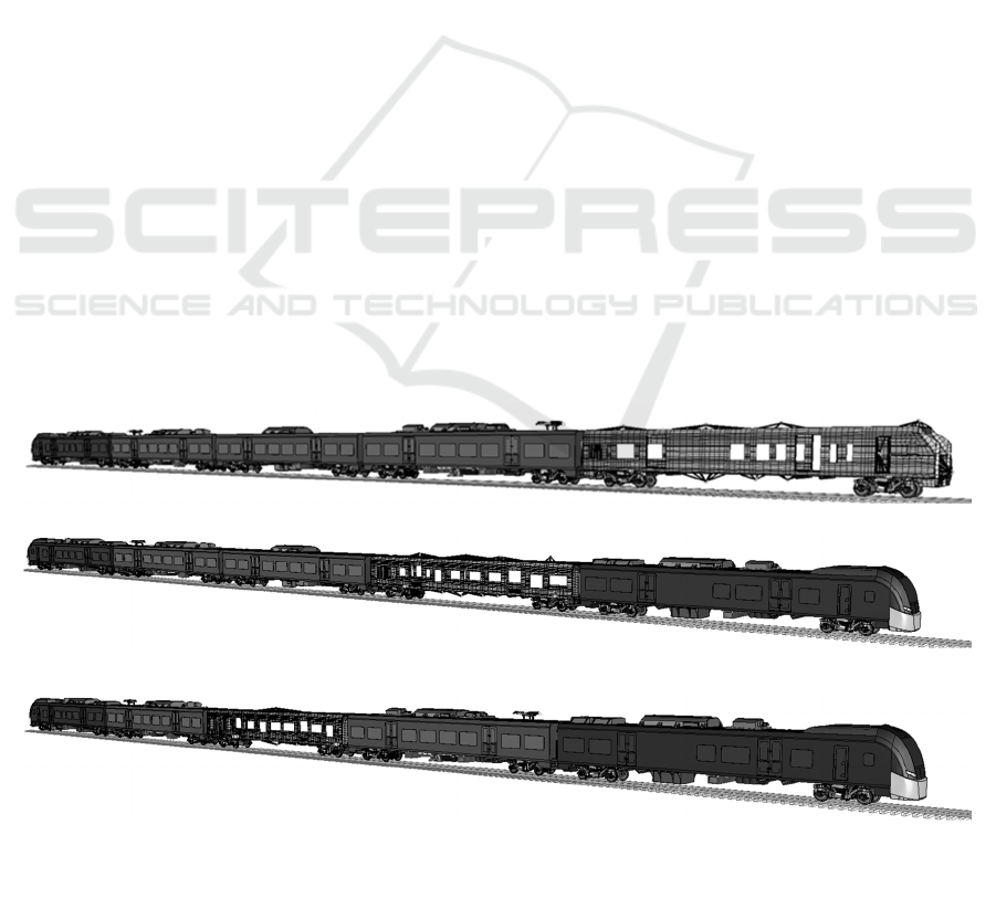
Figure 1: Hybrid dynamic models of an electric train taking into account the elastic properties of the body: a – the head
car; b – a trailer car with a pantograph; c – a trailer intermediate car.
Assessment of Passenger Comfort, Taking into Account Their Position in the Cabin and the Design Features of the Car
23
The net dose of motion sickness NR was
calculated on the basis of a motion model that takes
into account lateral vibrations and body rotation
(Persson, 2011):
𝑁𝑅 = 𝛽
+(𝛽
∙𝑎
+𝛽
∙𝑎
)∙
√
𝑡 (2)
where 𝛽
, 𝛽
– coefficients taken in
accordance with the model describing the movement
(Persson, 2011);
𝑎
, 𝑎
is the root-mean-square frequency-
weighted acceleration for the horizontal transverse
direction and rotation relative to the longitudinal axis.
The values of the motion sickness criterion were
evaluated only for passengers in the "sitting" position
on a scale from 0 to 3, where 0 – "no symptoms", 3 –
"moderate nausea".
A comparative analysis of approaches to
obtaining initial data for calculating comfort
indicators was carried out on the basis of a dynamic
hybrid model of a five-car coupling of a promising
domestic electric train ES2G "Lastochka" (Mitrakov,
2019) (Fig. 1).
The coupling model was developed in the
Universal Mechanism software package using the
subsystem method, according to which cars represent
hybrid subsystems of the first level, consisting of
subsystems of the second level: absolutely solid
subsystems describing the running gear – "bogies ",
and the bodies of cars in the form of elastic
subsystems – "body".
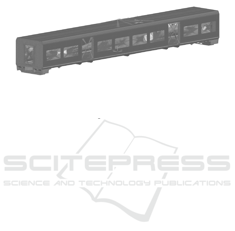
The load-bearing elements of the car body were
described using the finite element method. The
extruded aluminum profile of the bodies and the floor
of the cars were represented by three and four node
shell elements with five nodal degrees of freedom.
The mounted and internal equipment of the car was
modeled by placing special elements in the centers of
weights that allow assigning mass-inertia
characteristics to the nodal point (Fig. 2). The
subsystems of the running parts of the trolley car are
completely similar to those described in (Mitrakov,
2020).
The model verification procedure was carried out
by comparing the dynamic indicators obtained during
the simulation with the data of full-scale running tests
of the ES2G electric train. The following indicators
were considered in the verification: frame forces,
vertical and horizontal transverse accelerations of the
body at floor level in the pivot zone, indicators of
vertical dynamics of the first stage of spring
suspension and smoothness of travel in vertical and
horizontal directions. The maximum discrepancy was
revealed for the indicator of vertical accelerations of
the body of the motor head car - 18.6%, which is an
acceptable value when analyzing the dynamic loading
of the body and allows the possibility of using the
developed computer model to assess comfort
indicators (Mitrakov, 2020).
Increasing the accuracy of comfort forecasting
was achieved by including a resilient floor model in
the developed model. The description of the
connections between the car bodies and the floor
elements in the model was carried out by 1-d elements
of the "Cbush" type. The properties of these elements
were calculated as equivalent elastic-dissipative
characteristics of wooden beams and rubber gaskets
in the floor supports and were set along the three axes
of the car. A solid-state model Dummy Hybrid was
used to determine comfort indicators on models of
anthropometric dummies, describing a man with
anthropometric parameters corresponding to the 50th
percentile (Hybrid III 50th Male Dummy.
Humanetics Innovative Solutions, https: //
humanetics.humaneticsgroup.com; Kobishchanov,
2016). Models of dummies were considered in two
positions "sitting" and "standing". Solid models of car
seats were additionally introduced to accommodate
seated dummies. The dummies were placed in the
Figure 2: Finite element model of the trailer car body.
TLC2M 2022 - INTERNATIONAL SCIENTIFIC AND PRACTICAL CONFERENCE TLC2M TRANSPORT: LOGISTICS,
CONSTRUCTION, MAINTENANCE, MANAGEMENT
24
first three cars of the five-car coupling at the most
characteristic points. The total number of dummies is
26, of which 8 are in the standing position, 18 are in
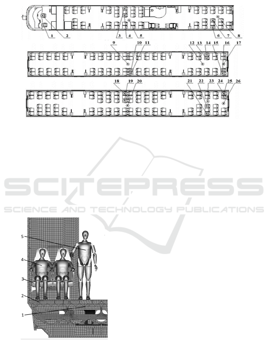
the sitting position. The placement of the dummies in
the car compartments is shown in Fig. 3.
An example of the location of dummies in the
"body" subsystem is shown in Figure 4.
Figure 4: The placement of the dummies in the interior of
the car body: 1 - the supporting structure of the car body; 2
– elastic elements of the floor support; 3- solid-state
elements of the seat; 4 – dummies in the "sitting" position;
5 - dummies in the "standing" position.
Modeling of rolling stock movement was carried
out on sections containing straight and curved
sections of the track with radii of 350 m, 600 m, 1000
m. The speed of movement was taken from 20 km/h
to the maximum allowed on the considered section of
the path.
3 RESULTS AND DISCUSSION
Based on the simulation results, the values of the
percentage of passengers experiencing discomfort
when moving in the curve were calculated - P
CT
and
the net dose of motion sickness – NR. The values of
the indicators were determined on the load-bearing
elements of the body; the supporting surfaces of the
floor and passenger seats; anthropometric dummies.
On the load-bearing structure of the body, the
worst values of comfort indicators among seated
passengers are observed when the motor head car is
moving with the implementation of the maximum
unbalanced acceleration at position 1 (Fig. 3a). The
value of the discomfort index in the P
CT
curve was
19.9%, the net dose of motion sickness NR was 1.4.
The best indicators of passenger comfort are observed
in the trailed intermediate car at position 19 (Fig. 3c),
the value of P
CT
was 16.2%, and the value of NR was
1.24. Comfort indicators for standing passengers
depend to a lesser extent on the location of the car in
the train. The lowest values of P
CT
were found in the
Figure 3: The placement of the dummies in the car compartments: a – motor head car; b – trailed intermediate car with
a pantograph; c – trailed intermediate.
1, 2 – models of a dummy in the "sitting in the chair" position of the driver and assistant;
3, 6, 11, 14, 15, 18, 21, 24 - models of a dummy in the "sitting in the chair" position of a passenger at the window;
4, 7, 10, 13, 16, 19, 22, 25 - models of a dummy in the "sitting in the chair" position of the passenger at the aisle;
5, 8, 9, 12, 17, 20, 23, 26 - models of a dummy in the "standing" position of a passenger in the aisle.
Assessment of Passenger Comfort, Taking into Account Their Position in the Cabin and the Design Features of the Car
25
trailed intermediate car for position 20 - 28.7%, and
the highest for position 26 – 30.5%. The analysis of
comfort indicators revealed their dependence on the
level of unbalanced acceleration. The best comfort
indicators were observed with equilibrium motion in
curves of a larger radius. With a decrease in the radius
of the curve, there was an increase in lateral
acceleration and a deterioration in passenger comfort.
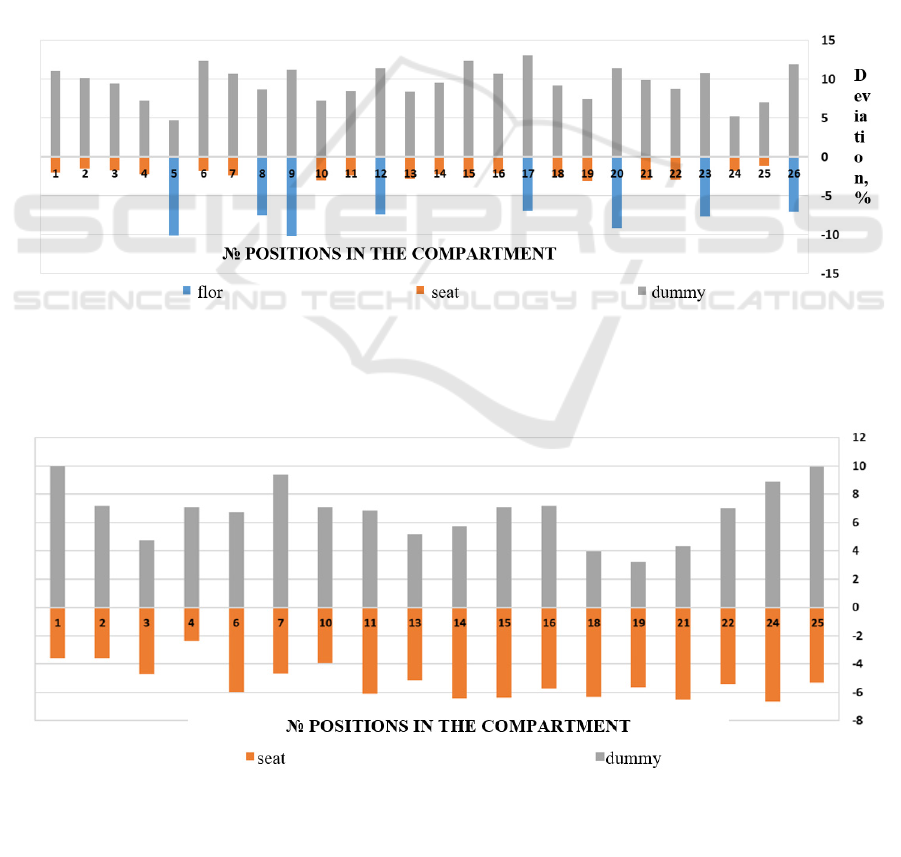
Figures 5, 6 show the relative deviation of the
values of Р
СТ
and NR, obtained taking into account
the elastic support of the floor of the car and
anthropometric dummies, relative to the values on the
metal structure of the body for the positions indicated
in Figure 3.
The analysis of the results showed that taking into
account the support of the passenger compartment
floor on elastic elements, as well as the registration of
accelerations on seats and dummies leads to a
deviation of comfort indicators relative to the values
on the supporting structure of the body:
− decrease in the P
CT
indicator measured at the
floor level by 7-10 %;
− decrease in the P
CT
indicator measured at the
passenger seat level by 1-3 %;
− increase in the P
CT
indicator measured on the
dummy body by 5-10 %;
− decrease in the NR indicator measured at the
passenger seat level by 2.3-3 %;
− increase in the NR indicator measured on the
dummy body by 3.8-10%.
Taking into account the design features of the
compartment, as well as measuring accelerations on
the support surface of the passenger seat, lead to a
Figure 5: Deviation of the P
CT
indicator with different measurement approaches, relative to the values on the supporting
structure of the body.
Figure 6: Deviation of the NR indicator with different measurement approaches, relative to the values on the supporting
structure of the body.
TLC2M 2022 - INTERNATIONAL SCIENTIFIC AND PRACTICAL CONFERENCE TLC2M TRANSPORT: LOGISTICS,
CONSTRUCTION, MAINTENANCE, MANAGEMENT
26

decrease in the analyzed indicators by 1-10%,
depending on the location of the check-in point. At
the same time, the indicators obtained on the basis of
accelerations registered on the body of the dummy
exceed the values obtained on the metal structure of
the body by 3.8 – 10%, which is explained by the
removal of the data registration point from the floor
level of the car and from the axis of rotation of the
body when it is tilted in curves.
4 CONCLUSIONS
The results obtained indicate the expediency of taking
into account the design features of the passenger
compartment and passenger accommodation in it
when analyzing the comfort level. The proposed
methodology, unlike traditional approaches, allows
you to predict the level of passenger comfort in
various areas of the passenger compartment, which
makes it possible to justify constructive solutions
aimed at increasing its level in local areas. The results
of the work can be applied in the development of
systems for active damping of floor elements and
passenger seats to increase passenger comfort, design
of new types of rolling stock with low natural
frequency of car bodies.
REFERENCES
CEN 12299 Railway applications — Ride comfort for
passengers — Measurement and evaluation. 2009.
Brussel: European Committee for Standardization. p.
90.
Romain, Yu. S., 2014. Dynamics of the railway crew in the
rail track. Methods of calculation and testing. p. 210.
Ling, L., Zhang, Q., Xiao, X., Wen, Z., Jin, X., 2018.
Integration of car-body flexibility into train–track
coupling system dynamics analysis. Vehicle System
Dynamics. 56. 4. pp. 485-505.
Zhou, J. et al., 2009. Influences of car body vertical
flexibility on ride quality of passenger railway vehicles,
Proceedings of the Institution of Mechanical Engineers,
Part F. Journal of Rail and Rapid Transit, 223(5). pp.
461-471.
Kovalev, R., Lysikov, N., Mikheev, G., Pogorelov, D.,
Simonov, V., Yazykov, V., Zakharov, S., Zharov, I.,
Goryacheva, I., Soshenkov, S., Torskaya, E., 2009.
Freight car models and their computer-aided dynamic
analysis. Multibody System Dynamics. 22. 4. pp. 399-
423.
Shorokhov, S. G., 2015. Justification of technical solutions
to ensure the mechanical safety of passenger cars in
case of emergency collisions: dissertation of the
Candidate of Technical Sciences: 05.22.07.
Monography. p. 147.
Polanco, M. A., Littell, J. D., 2011. Vertical Drop Testing
and Simulation of Anthropomorphic Test Devices. 67th
Annual Forum. – Virginia Beach, VA., p. 18.
Perez, O., 2010. Evaluation of the FAA Hybrid III 50th
percentile anthropometric test dummy under the FAR
23.562 and 25.562 emergency landing conditions for
the combined horizontal-vertical dynamic loading.
University of Catalonia, p. 76.
Rabinovich, B. A., 2006. Human safety during
acceleration. (Biomechanical analysis). Monography.
p. 208.
Antipin, D. Y., Kobishchanov, V. V., Lapshin, V. F.,
Mitrakov, A. S., 2017. Analysis of vibrational load
influence upon passengers in trains with a compulsory
body tilt. IOP Conference Series: Materials Science
and Engineering. – IOP Publishing. 177. pр. 1-7.
Antipin, D. Ya., Vaulin, P. V., Lapshin, V. F., Mitrakov, A.
S., 2017. Investigation of passenger comfort level in
trains with forced body tilt in curves by methods of
mathematical modeling. Transport of the Urals. 3 (54).
pp. 3-8.
Antipin, D. Ya., Shorokhov, S. G., Bondarenko, O. I., 2018.
CAD/CAE-technologies application for assessment of
passenger safety on railway transport in emergency.
IOP Conference Series: Materials Science and
Engineering. 327. 022007 (1-7).
Bondarenko, O. I., 2021. Assessment of the safety of
passenger cars in case of an emergency rollover on the
embankment. Bulletin of the Bryansk State Technical
University. 9 (106). pp. 49-54.
Persson, R., 2011. Tilting trains: enhanced benefits and
strategies for less motion sickness. Doctoral.
Stockholm. p. 36.
Mitrakov, A. S., 2019. Selection and justification of rational
parameters of the system of forced tilt of the body of a
domestic electric train. Bulletin of UrGUPS. 4 (44). pp.
65-75.
Mitrakov, A. S., 2020. Justification of the parameters of the
system of forced inclination of the car bodies:
dissertation of the Candidate of Technical Sciences:
05.22.07. p. 171.
Hybrid III 50th Male Dummy. Humanetics Innovative
Solutions.
https://humanetics.humaneticsgroup.com/products/ant
hropomorphic-test-devices/frontal-impact/hybrid-iii-
50th-male/hybrid-iii-50th-male.
Kobishchanov, V., Antipin, D., Mitrakov, A., Shorokhov,
S., 2016. Use of anthropometric dummies of
mathematical models in the safety and comfortableness
analysis of a passenger rolling stock. IOP Conference
Series: Materials Science and Engineering. 012065.
Assessment of Passenger Comfort, Taking into Account Their Position in the Cabin and the Design Features of the Car
27
