
Structural and Load Modifications in Finite Element Analysis
M. L. Musayeva
1
and P. S. Tsamaeva
2
1
Kadyrov Chechen State University, 32 Sheripov Street, Grozny, Russia
2
Department of Technological Machines and Equipment, Grozny State Oil Technical University named after Academician
M. D. Millionshikov, 100 H A Isaeva pr, Grozny, Russia
Keywords: Structure, loads, software packages, complex analysis, modifications, Finite Element Analysis.
Abstract: The following work was conducted to outline the alternation of structure and loads in the finite element
analysis or analysis in general. Nowadays, computers are able to handle complex analysis but yet the analysis
sometimes requires to be solved. With the simplified version, analysis can be done in a faster way and with
the fewer errors as well. Hence, the following work outlines the main aspects of the structure and loads
alternation. Gives different types of examples of structure and loads alternation. Also, the work shows
advantages and disadvantages of alternation of structure and loads during analysis.
1 INTRODUCTION
With the advancement of computer calculations, most
of the complex analysis can be carried out in a short
amount of time. In the past, it would take hours and
days to tackle even the simplest calculations.
Therefore, with the growth of computing power, there
are new ways to solve some complex problems and
even problems that were unsolvable in the past due to
the lack of solving methods.
Modern days give researchers powerful tools for
analysis. With the improvement of computing power,
various tools have emerged. These tools (software
packages) comes in wide diversity. Some are created
for the modeling purposes, some for analysis, and
ones with the capability to perform both.
These tools can analysis a given problem with the
accurate results if they are carried out correctly. The
quality of output results depends on many aspects. In
the beginning, the correct method selection can
increase the accuracy of the results. Many methods
are used for different tasks, and therefore inaccurate
or even incorrect results will be obtained when using
the wrong method to solve a problem. The second
thing is the knowledge of the researcher. For the
correct output values, the prescribed steps for analysis
needs to be carried out correctly. Therefore, the
researcher must be qualified in the given problem.
The third is correct representation of the tackling
problem and the application of boundary conditions.
The analyzing structure must be matching to the real-
world object. If some parts of the analyzing structure
differ from the real-world one, the output results will
as well be different. Boundary conditions play a vital
role in whole analysis. Even a slight displacement in
applications of these conditions will give different
output data. The last one is the interpretation of the
results. There is a lot of data after analysis solved.
Therefore, it is important to extract correct values and
the skills to correctly interpret them. Of course, there
are many other things to be looked up for the quality
results output, but the main ones are mentioned in this
work (Jiménez, 2021; Ordoñez, 2021).
Sometimes correct answers are not necessary in
the analysis, but tendency. Some researchers use tools
to predict results or in other way to see a tendency of
results. In this case, the results will not match the real-
world values, but will be on the same path. Hence, the
structure can be changed or simplified. Similarly, the
boundary conditions also will be altered. In other
terms, it can be noted as a simplification or
idealization of structure and loads. The following
work will look into the use and reasons of altering the
appearance and acting loads to it.
2 ALTERNATION OF
STRUCTURE AND LOADS
For the analysis to be performed, some initial object
is
required. This object or a structure can be in any
Musayeva, M. and Tsamaeva, P.
Structural and Load Modifications in Finite Element Analysis.
DOI: 10.5220/0011556000003524
In Proceedings of the 1st International Conference on Methods, Models, Technologies for Sustainable Development (MMTGE 2022) - Agroclimatic Projects and Carbon Neutrality, pages
127-130
ISBN: 978-989-758-608-8
Copyright
c
2023 by SCITEPRESS – Science and Technology Publications, Lda. Under CC license (CC BY-NC-ND 4.0)
127
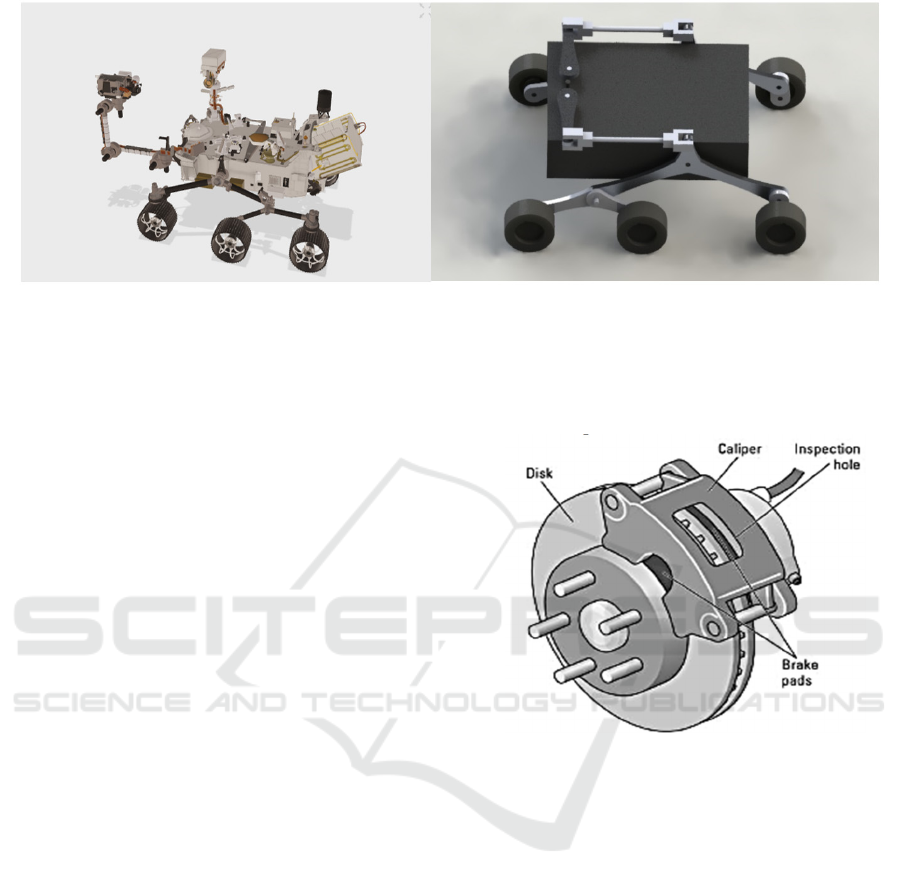
Figure 1: Mars rover.
shape, size, state and etc. Usually, a structure has
different appearance and can be simple in one case
and complex in others. Consequently, simple one will
be easier to be modelled and analyzed than the
complex one. The researcher has to make decision to
analysis the structure as it is or alter the appearance
and hence change the acting loads. Of course, both
simple one and complex one can be analyzed as they
are. But most of the time, both of the structures are
simplified for ease of analysis.
There are two main reasons for alternation of
structure and loads. The first of these, as was
mentioned before, is related to the ease of analysis
and the methods used. The second one is for working
out different scenarios of how the structure will act by
changing the appearance and the acting loads on it.
2.1 Structure Alternation
The following paragraph will be devoted to examples
of alteration in the structure. By examining the
examples, one can notice that some of structures are
altered more, while others are not. In figure 1
presented Mars’ Rover, which is currently used for
the exploration of water on Mars.
Comparing two models, one can conclude that the
difference in parts is vast, but the main body forms
are represented in a simpler way (Magomedov, 2022;
NASA SCIENCE; Daniela, 2015). Figure 2a and b
illustrates the structure of the braking system. The
representation of one object can be done in many
ways, as illustrated in the figure 2. In one case, the
brake system is represented with the closer
appearance to the real-world system, and in another
one, it has more simple modeled parts. As it was
mentioned the appearance, complexity, forms and etc.
depends on the researcher. The smartphone screen is
shown in the figure 3. Figure 3 shows translation of
3D model to 2D model (Magomedov, 2019). It is not
only 3d model simplification one can get, but 2d
simplification too. Of course, there are a lot of
different ways and methods to simplify the structure
that are not represented in this work.
Figure 2a: Disc brake system.
2.2 Alternation of Loads
As it was mentioned earlier, the second thing that can
be altered is the loads. First of all, by just altering the
structure appearance, the loads will respectively
change. Second thing is when 3D model is translated
to 2d model as illustrated in the figure 4 (López, 2012;
Enterfea). As model is translated to 2D model, some
loads are changed or reduced. There is another
method used in the analysis, which is segments
removal. In which the structure is cut to a smaller
portion and then one of the segments is analyzed.
In this method not only the structure is simplified
but also loads simplification or reduction take place.
MMTGE 2022 - I International Conference "Methods, models, technologies for sustainable development: agroclimatic projects and carbon
neutrality", Kadyrov Chechen State University Chechen Republic, Grozny, st. Sher
128
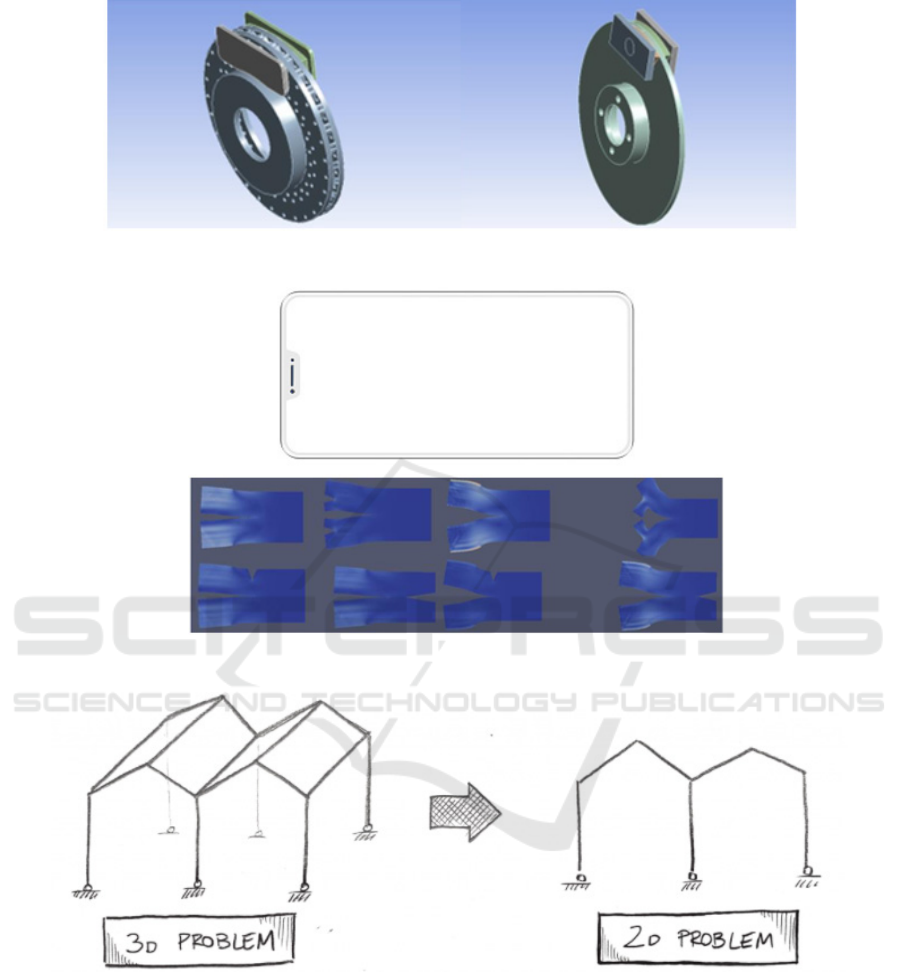
Figure 2b: Disc brake system.
Figure 3: Smartphone screen.
Figure 4: Beam models.
3 ADVANTAGES AND
DISADVANTAGES
As it was discussed above, simplification of the
structure leads to easy analysis. By the simplification
of the structure nodes or finite elements get reduced
(of course, mesh can be added to refine the divisions
of structure even with the less parts), hence making it
easier for the solver to calculate. It is also fair to
mention that complex structures often give errors.
Errors are inevitable part of the modern tools for the
analyses. They occur way more often and there are a
lot of reasons for their occurrence. However,
simplification can sometimes eliminate them. If given
the simplified structure to the solver it will calculate
it faster (in some cases it can introduce more errors)
Structural and Load Modifications in Finite Element Analysis
129

hence reducing time needed. In any production of
goods, technique, food or in this case any analysis
reduction of time is essential for the future
prosperous. Time in our society is equals to profit,
which means any reduction in time will positively
effect in any given task.
With the advantages, there are some
disadvantages for structure alternation before the
analysis. First and the main disadvantage is precise
values, which are collected at the end of the analysis.
By the idealization or alternation of any given
structure, the output results will only illustrate
tendency or somehow close results, but no correct
results. Therefore, the researcher should choose the
correct method and decide, which result are expected
from the analysis, whether precise or correlates with
the correct values. The other outcome of alternation
is incorrect values, which is not even correlates with
the tendency. With the simplification of the structure,
the output values can go in any direction, meaning
that they won’t carry any value at the end.
Introduction of new error also possible with the
alternation.
4 CONCLUSIONS
To conclude, the following work was performed to
understand the use of alternation of the structure in
the analysis. The work described the process and the
meaning of the alternation or idealization of the
structure. The examples also were presented in this
work to illustrate the different ways of alternation.
The importance of use of these methods were also
presented with the advantages and disadvantages.
With the improvement of the software, the alternation
process will be easier to performed, but today it’s a
method that researchers use manually.
REFERENCES
Jiménez, H. F., et al, 2021. IOP Conf. Ser.: Earth Environ.
Sci. 776. 012012.
Ordoñez, M., et al, 2021. Propuesta metodológica para el
diseño de prótesis utilizando CAD generativo y análisis
CAE. p. 7
Magomedov, I. A., José, Luis Ordoñez-Avila, Bagov, A.
M., 2022. Statistical evaluation of a robotic six-wheel
structures mechanism based on motion simulation.
NASA SCIENCE (Mars exploration program) Mars
Perseverance Rover, 3D Model.
https://mars.nasa.gov/resources/25042/mars-
perseverance-rover-3d-model/.
Daniela, N. Lastra. 2015. Modelado y control dinámico de
un Aerogenerador. Universidad de Cantabria,
Cantabria.
Magomedov, I. A., et al, 2019. IOP Conf. Ser.: Earth
Environ. Sci. 378. 012064.
Enterfea, 2D vs 3D Finite Element Analysis (with
examples). https://enterfea.com/2d-vs-3d-finite-
element-analysis/.
López, V., 2012. Ingeniería de la Energía Eólica.
Barcelona: Marcombo S.A.
MMTGE 2022 - I International Conference "Methods, models, technologies for sustainable development: agroclimatic projects and carbon
neutrality", Kadyrov Chechen State University Chechen Republic, Grozny, st. Sher
130
