
Computational Fluid Dynamics to Reach a High-fidelity Simulator of
Performance in Rowing
Alban Leroyer
1 a
and Sophie Barré
2
1
Nantes Université, Ecole Centrale Nantes, CNRS, LHEEA, UMR 6598, F-44000 Nantes, France
2
CREPS Pays-de-la-Loire, 5 Avenue de la Babinière, 44240 La Chapelle-sur-Erdre, France
Keywords:
Rowing, Computational Fluid Dynamics (CFD), Numerical Simulation, High Performance Computing
(HPC), Fluid Dynamics, Fluid-Structure Interaction (FSI), Biomechanics, Performance Analysis.
Abstract:
The massive growth of computational power and the advances of the numerical models make the use of numer-
ical simulations to help analysing and improving sport performance achievable. However, it is still challenging
because the physical configurations generally involved complex coupled problems and because human is part
of the system. Furthermore, elite athletes already operate near an optimal point. As a consequence, the mod-
elization of all the phenomena that come into play has to be accurate enough to be useful and relevant when
the objective is to analyse interactions and to give reliable trends while varying some parameters. The case
of rowing is presented here, through the development of SPRing (Simulator of Performance in Rowing), a
high-fidelity simulator of the global system "boat-oars-rower(s)" coupled with the resolution of the Reynolds-
Averaged Navier-Stokes equations to provide fluid forces acting on it.
1 INTRODUCTION
During the past twenty years, relationship between
Centrale Nantes, CREPS des Pays de la Loire and the
French Rowing Federation has been forged through
various research projects linked to performance sup-
port, including experimental campaign in towing tank
using specific devices to investigate the flow physics
around hull and blades, on-the-water measurements,
and numerical validation. With both the upcoming
2024 Olympic and Paralympic Games in Paris and
the achievements in HPC and in CFD over the past
decade, time has come to capitalize all the knowledge
acquired to develop a high-fidelity simulator of the
boat-rower(s)-oars system coupled with a CFD flow
solver to better understand the physics of this complex
mechanical system. Preliminary results look very re-
alistic and promising, and illustrate the relevance of
some technical choices which were made. On this
basis and before being exploited, a deeper validation
step has to be carry out, which is a mandatory but not
straighforward prerequisite. The pursued objective of
this challenging tool is to help coaches and athletes in
the quest of the best performance.
a
https://orcid.org/0000-0001-5427-1082
2 MODEL OF THE GLOBAL
SYSTEM
BOAR-OAR(S)-ROWER(S)
The global system Boat-Oar(s)-Rower(s), denoted by
BOR system thereafter, is considered from a mechan-
ical and inertial point of view as a system composed
by a set of rigid bodies (even if deformed by the fluid
loads and rower loads, the oars keep their inertia prop-
erties unchanged, which is a valid assumption). The
mass of the BOR system is conserved in time whereas
the global inertia properties (position of the center of
gravity and inertia matrix) changes according to the
internal degrees of freedom defined by the position of
the oars and of the rower(s) with respect to the boat.
Once defined the floating frame of reference linked
to the boat where the origin is set at the keel line at
the middle of the boat (see figure 1), the resolution of
the dynamics of the BOR system is then reduced to
the resolution of the Newton’s law of a system which
inertia properties changed in time and subjected to
external forces, similar to what is done in (Leroyer
and Visonneau, 2005). The external degrees of free-
dom (DOF) of the BOR system which are solved are
namely the position and the orientation of the hull as a
function of time: the hull kinematics is thus the output
Leroyer, A. and Barré, S.
Computational Fluid Dynamics to Reach a High-fidelity Simulator of Performance in Rowing.
DOI: 10.5220/0011549300003321
In Proceedings of the 10th International Conference on Sport Sciences Research and Technology Support (icSPORTS 2022), pages 117-124
ISBN: 978-989-758-610-1; ISSN: 2184-3201
Copyright
c
2022 by SCITEPRESS – Science and Technology Publications, Lda. All rights reserved
117
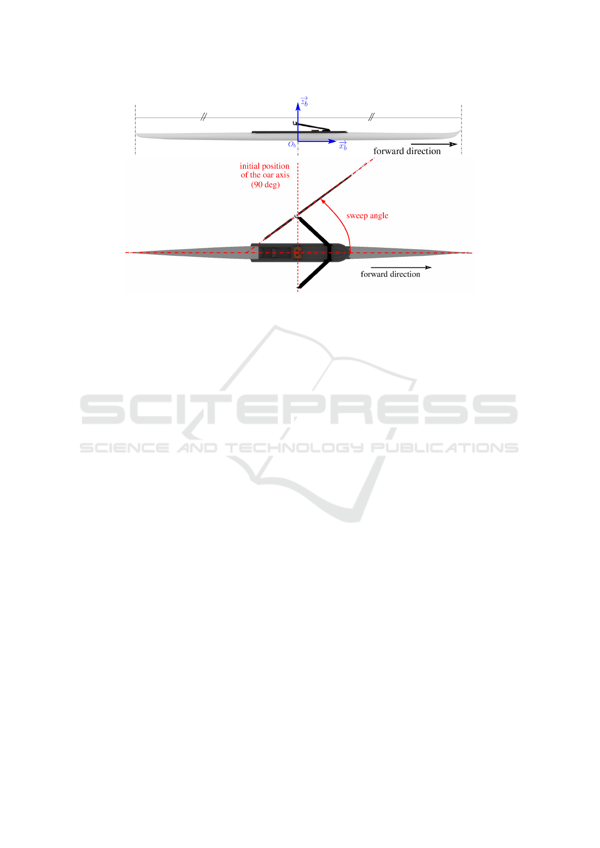
Figure 1: Parameterization of the system.
of the resolution.
Except the gravity, the major part of the external
forces, strongly coupled to the BOR system, comes
from the hydrodynamic forces acting on the hull and
on the blades. To reach an high-fidelity model, they
are computed using CFD (see section 3). Other aero-
dynamic forces which contributions are limited, are
taken into account through simplified analytical mod-
els. The motions of the rower(s) and of the oars
with respect to the boat represent the internal DOF
of the BOR system. They are responsible both for the
change of inertia parameters of the system and for the
propulsive force through the generated hydrodynamic
forces. Except the induced deformation of the shaft
which are solved together with the resolution of the
dynamics of the hull (Robert et al., 2018), all other
internal DOF are imposed to reproduce the variety
of kinematics found among elite rowers. Details are
given in section 4.
3 EXTERNAL HYDRODYNAMIC
LOADS AND COUPLING
3.1 Need for High-fidelity CFD Model
More than two decades ago, experimental research
works were done to characterize flows involved in
rowing, especially around the blade. A specific device
was designed and used in a towing tank to reproduce
the main characteristics of this violent flow using real
oars. This initial goal was to better understand the
physics of this flow and to build simplified models
(Barré, 1998; Barré and Kobus, 2010). Even if these
models can reproduce the right order of magnitude
and are useful to quickly test the simulator, they will
never be accurate enough to take into account all the
subtle interactions which appear during the propul-
sive phase, especially during the catch phase, which
is essential to the propulsive force generation of the
whole stroke. Given the high-accuracy requirement
to address sensibility analysis to small variations of
parameters, it was decided to directly couple the high-
fidelity model based on CFD computations using the
ISIS-CFD solver to power the fluid forces interacting
with the BOR system (on the hull and on the blade),
without any compromise in accuracy (Robert et al.,
2018). In this challenging task, this unique experi-
mental database turned out to be of great help to vali-
date the CFD tool (Robert, 2017; Robert et al., 2018).
Such a work has never been reported in the literature.
(Formaggia et al., 2009) coupled a simplified 6 DOF
model of the BOR system with a CFD flow resolu-
tion around the hull while imposing analytical law of
fluid loads for the blades. (Sliasas and Tullis, 2009;
Sliasas and Tullis, 2010) coupled a 1 DOF model of
the BOR system with CFD flow resolution around the
blade (without taking into account either vertical mo-
tion or shaft flexibility) and while using an analyti-
cal drag-based hull velocity model: results exposed
in (Sliasas and Tullis, 2009) seem somehow nonphys-
ical, especially when the propulsive force become un-
expectedly negative at the end of the drive phase but
which, oddly enough, does not appear in (Sliasas and
Tullis, 2010). Shaft flexibility is investigated sepa-
rately without coupling with a BOR system in (Sliasas
and Tullis, 2011) , but using a one-way coupling then
requiring to repeat several times the simulation to
converge.
icSPORTS 2022 - 10th International Conference on Sport Sciences Research and Technology Support
118
3.2 ISIS-CFD Solver
ISIS-CFD is an incompressible unsteady Reynolds-
Averaged Navier–Stokes (RANS) solver devel-
oped by ECN-CNRS, available as a part of the
FINE
T M
/Marine computing suite which is dedicated
to marine applications. This solver is based on a
cell-centered unstructured finite-volume method. Ad-
vanced capabilities such as fluid structure interac-
tion, automatic adaptive grid refinement technique
and overlapping grid technology are required in the
present context to achieve both accurate and efficient
computations. This worldwide used tool has been val-
idated through various CFD workshops in ship hy-
drodynamics (Deng et al., 2012; Deng et al., 2015;
Queutey et al., 2021). As previously mentionned, a
hard validation work has also been carried out for the
specific flows involved in rowing using previous ex-
perimental research works on this topic (Barré, 1998;
Barré and Kobus, 2010; Robert, 2017; Robert et al.,
2018).
3.3 Co-simulation between ISIS-CFD
and SPRing
To reach an efficient and robust algorithm for this
partitioned approach, the coupling iteration is done
within the non-linear iterations of the fluid solver.
This implicit internal coupling solves both the dynam-
ics of the hull and the deformation of the oar shafts
computed by SPRing (Simulator of Performance in
Rowing) using the current fluid loads and then update
these kinematic modifications to the fluid part. The
model of flexibility of the shaft is based on a beam
model with a variable stiffness law along its length.
The parameters of this law has been calibrated using
a specific flexibility test bench for oars, which is not
described here.
Data transfer between the two codes is done
through a TCP/IP socket-based protocol, using the
ZeroMQ distributed message library (Akgul, 2013).
As other fluid-structure interaction in hydrodynamics,
a stabilization procedure based on an artificial added
mass method is used to tackle the destabilising added-
mass effects (Yvin et al., 2018).
4 CONTROL OF THE INTERNAL
DOF
As previously described, the internal DOF of the BOR
system are given by the position of the oar and the
position of the rower. In most of research works in-
volving a model of rower, a kinematic control (time
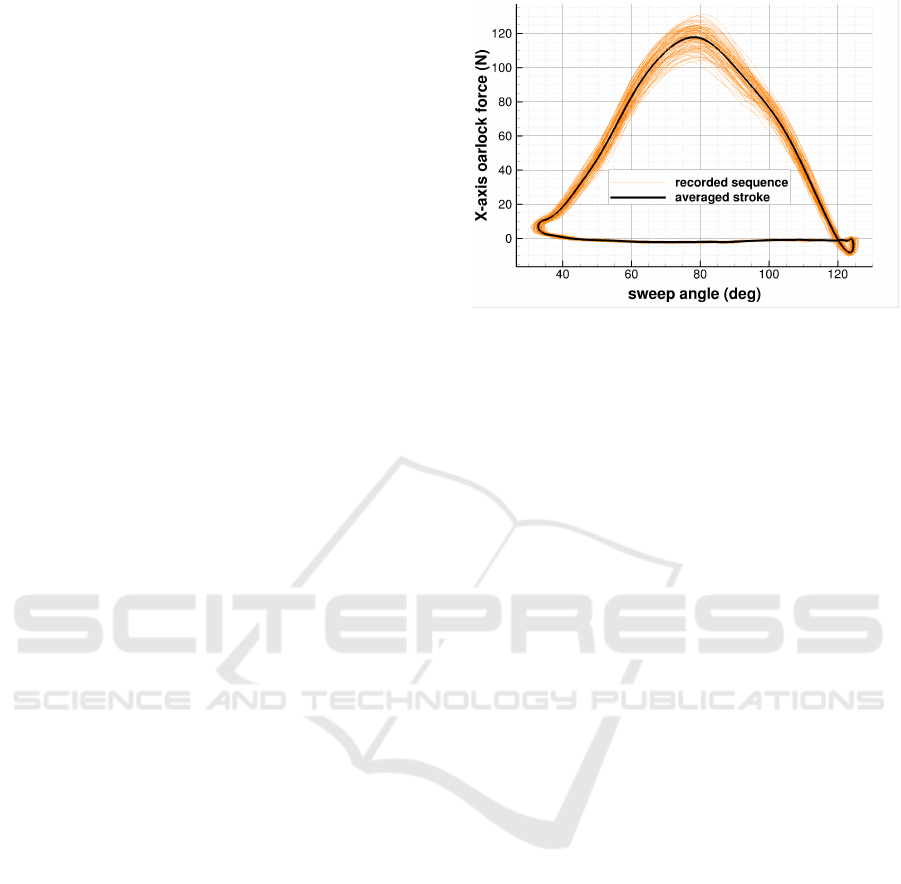
Figure 2: Force as a function of sweep angle, raw data and
averaged procedure.
law of join angle (Cabrera and Ruina, 2006; Rongère
et al., 2011) or a dynamics control (time law of join
torque (Pettersson et al., 2014)) is used to drive the
posture of the rower in time and induce the motion of
the oar. Here it is done in the opposite way: the sweep
angle of the oars as well as the vertical height of the
blade with respect to the water surface are imposed in
time. The main motivation of this choice is the ease to
reproduce real crews since the sweep angle is a data
which is available at each on-the-water measurement.
It also offers the possibity to modify the rowing stroke
by modifying the temporal law of the sweep angle.
The vertical position of the blade is far much tricky
to track in-situ. At that time, this data is not yet mea-
sured. However, thanks to video analysis, a paramet-
ric model can be built to reproduce as accurate as pos-
sible the real path, as described in section 4.2. Tech-
nical gesture which identified each rower, called here
gesture signature, is reproduced through some para-
metric curves driving the athlete position.
4.1 Oar Motion Input
Sweep angle is given as a time series. When dealing
with an on-the-water measurement during a sequence
at constant stroke rate, an averaging procedure is ap-
plied to work with a pure periodic signal, see figure 2.
A synthesis procedure has been developed too, which
enable to create a B-spline based parametric model of
the sweep angle and then to play with the parameters
to modify the rowing stroke. An illustation of this
fonctionnality is given in section 5.
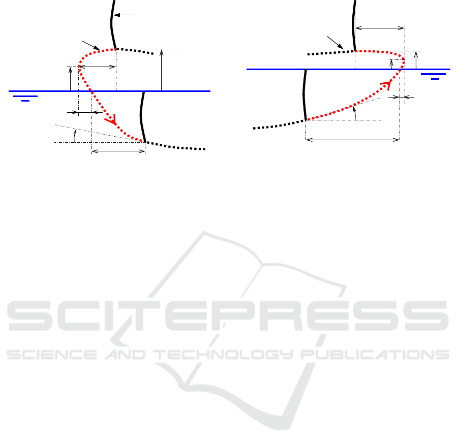
Vertical position of the blade is modeled by a set
of 16 parameters for the whole stroke: twelve of them
are dedicated to define both the catch phase (see fig-
ure 3) and the release phase (see figure 4). The oth-
ers are dedicated to model the link between these two
phases.
Computational Fluid Dynamics to Reach a High-fidelity Simulator of Performance in Rowing
119
blade
air
water
trajectory of the
blade bottom
H
θ
min
∆t
i
∆θ
i
α
∆θ
0
H
0
∆θ
c
a
Figure 3: Parametrization of the vertical motion of the blade
during the catch phase.
H
0
: blade height with respect to the water at the begin-
ning of the catch phase,
∆θ
0
: starting sweep angle of the catch phase minus
minimum sweep angle,
H
θ
min
:blade height at minimum sweep angle,
∆θ
c
a
: angular deviation before immersion,
∆t
i
: immersion time,
α: slope of immersion at the end of the catch phase. of
immersion.
4.2 Rower Gesture Signature
Even if this is not what’s happen in real life, the whole
motion of oars is imposed using the input data and
model described previously, and the rower moves ac-
cordingly. However, for a given position of oars,
there is multiple rower positions satisfying the con-
straints (hands attached to handles, foot attached to
the stretcher and buttocks following the sliding seat
path). The temporal evolution of limbs position sat-
isfying the constaints define the gesture signature. To
reproduce a variety of gesture signatures, evolution
of legs bending, trunk inclination and arms bend-
ing are driven through parametric curves, function of
their respective stretching ratio at the current posture.
The temporal evolution of the rower position is then
computed incrementally : at each new time step, the
stretching ratio are used to find the contribution of
each part of the rower body involved in the oar po-
sition increment, as shown in the figure 5 at the left.
The resulting rower kinematics is shown at the right.
As an illustration, it can be seen that at the end of the
driving phase as well as the beginning of the recov-
ery, arms are the limbs which is mainly responsible
of the oar motion whereas around the catch phase, the
oar motion is mainly due to the modification of legs
bending. Some additional features, such as spine cur-
water
air
trajectory of the
blade bottom
β
H
θ
max
∆t
e
∆θ
e
∆θ
r
a
∆θ
1
H
1
Figure 4: Parametrization of the vertical motion of the blade
during the release phase.
∆t
e
: exit time,
β: slope of exit at the beginning of release phase
∆θ
r
a
: angular deviation after exit,
H
θ
max
:blade height at maximum sweep angle,
H
1
: blade height with respect to the water at the end of
the release phase,
∆θ
1
: maximum sweep angle minus final sweep angle
of the release phase.
vature, lift of the heels and strech of the shoulders
close to the catch, have also be implemented to enrich
the gesture signature. Special care need to be done
for the whole kinematics which is imposed. Sweep
angles, blades height and limbs motion have to be de-
fined with smooth enough temporal series (equivalent
to functions of class C
2
) to obtain a smooth response
of the hull dynamics. Other input data as density and
geometry of each members of the rower are mainly
based on the work described in (Yeadon, 1990) and
(Leva, 1996), and set them according to the rower
morphology.
5 RESULTS
A first preliminary simulations have been carried out
using a quite coarse mesh of around 2 million cells
to provide a proof-of-concept. An initial phase starts
with a speed-up of the hull using an imposed for-
ward velocity ramp up to a guess velocity while keep-
ing solving heave and pitch (see figure 6). In the
meanwhile, the rower moves from his initial position
(sweep angle 90°, fully stretched legs, vertical trunk)
to the catch phase with a smooth kinematic connec-
tion at the configuration when the height of the blade
reaches its maximum value. This connection is done
at the time when the whole resolution of the dynamics
starts.
icSPORTS 2022 - 10th International Conference on Sport Sciences Research and Technology Support
120
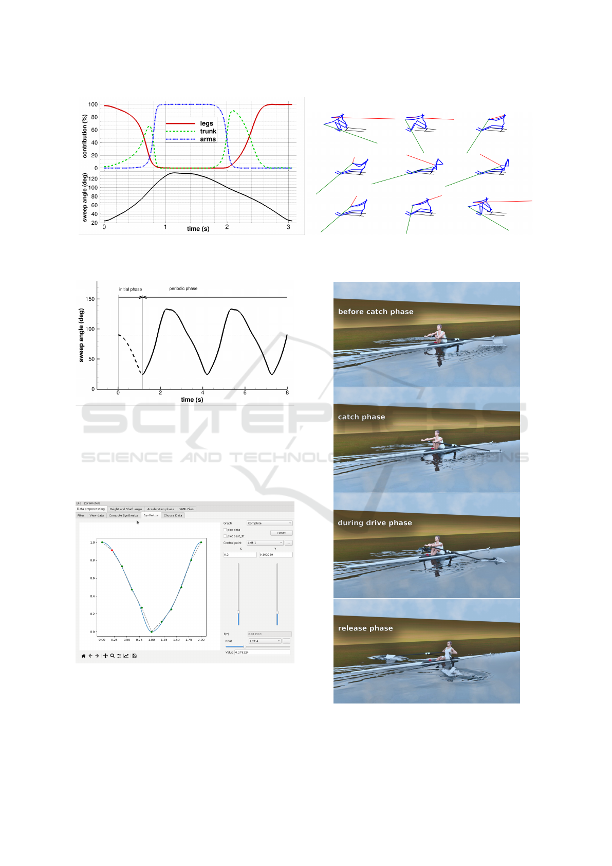
Figure 5: On the top left, contribution of legs bending, trunk inclination and arms bending to the oar rotation as a function
of time, resulting on the incremental procedure. On the bottom left, averaged sweep angle as a function of time coming from
measurement. On the right, resulting sequence of rower postures for a whole rowing stroke.
Figure 6: Imposed sweep angle as a function of time includ-
ing the initial phase.
A specific Graphical User Interface (GUI) has
been developed to set all the input parameters, from
the generation of the periodic sweep angle to the mor-
phology of each rower (see figure 7).
Figure 7: SPRing input GUI showing the synthesis of a
given sweep angle with B-spline.
Considering the final objective of the tool, an
important aspect of the project concerns the realis-
tic rendering of the simulation, see figure 8. It has
Figure 8: Realistic rendering of the co-simulation
SPRing/ISIS-CFD. Computed free surface are imported
from CFD simulation as STL triangulation.
Computational Fluid Dynamics to Reach a High-fidelity Simulator of Performance in Rowing
121
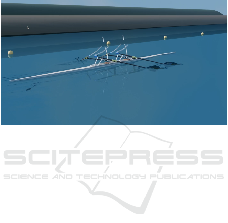
Figure 9: Stickman rendering of a double skull with a co-simulation SPRing/ISIS-CFD. Morphology and gesture signature
can be defined specifically for each rower.
been developed using the open-source Blender soft-
ware (Community, 2018). Such a post-treatment is
important as a communication facility with coaches,
but also to easier confront the reality with the simula-
tion. However, due to the complexity to fit automat-
ically the human mesh with the morphology of each
rower, this approach has been put aside at the moment
in favor of a less realistic "stickman" representation
of rowers, see figures 9 and 10. This fully automatic
mode, still using Blender, is driven through another
dedicated GUI. Specific outputs (hull kinematics, oar
deformation, incident velocity around the blade,...)
can be visualized through synchronized graphs or by
superimposed arrows in a multi-view scene, which
greatly facilitate the physical analysis too.
6 CONCLUSION AND
PERSPECTIVE
To achieve the scientific challenge of a high-fidelity
model of the BOR system, a multi-body system has
been developed to accurately model the kinematics of
the rower with respect to its environment. It is the next
step after previously published reference CFD results
(Robert et al., 2018; Robert et al., 2014), on which
it relies. This imposed kinematics is driven both by
some gesture parameters and time evolution of sweep
angle of each oar (which can be provided from in-situ
data measurements) and height of the blade with re-
spect to the free surface. The dynamics of the global
system is then reduced to the dynamics of the hull,
which is solved by integrating the major fluid forces
acting on both the hull and the blades through CFD
resolution (Robert et al., 2018; Robert et al., 2014).
The original kinematic approach of the control of the
gesture signature has been motivated to be in line with
the objective to have both an accurate description and
the most operational tool to analyse and serve perfor-
mance in rowing. Before playing this role, an exten-
sive step of validation for these coupled simulations
needs to be investigated using on the water measure-
ment. This validation step is crucial because Science
can bring a new insight on sport performance, only if
the model lives up to the expectations in term of ac-
curacy so that the physical analysis of the phenom-
ena can be trustingly carried out. The preliminary
results obtained with the high-fidelity co-simulation
look very realistic and is a source of motivation to pur-
sue this path. In parallel of that, more advanced me-
chanical analysis (load on human joints, power con-
sumption, efficiency,. . . ) is planned to benefit from all
the data which are computed. At term, such tool tar-
gets to bring objective and unbiased criteria for ques-
tions which have only empirical answer up to now.
icSPORTS 2022 - 10th International Conference on Sport Sciences Research and Technology Support
122
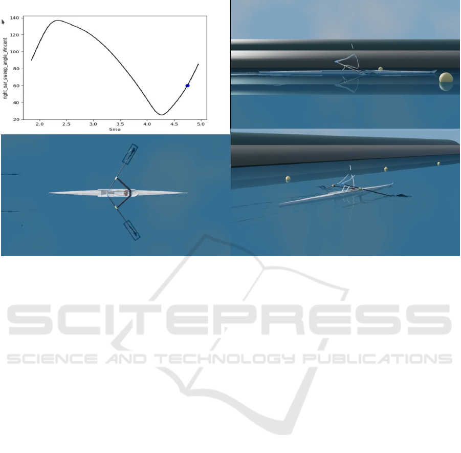
Figure 10: Multi-view stickman rendering, synchronized with the graph showing the sweep angle as a function of time, made
by the SPRing output GUI.
ACKNOWLEDGEMENTS
We would like to thank the students of the "Scientific
Challenge 2024" project of Centrale Nantes who are
participated to the development of SPRing. This work
benefits from HPC resources of ICI-CNSC through
the call GLICI/2018. It is also granted access to the
HPC resources of GENCI-CINES under the alloca-
tion A10856 made by GENCI.
REFERENCES
Akgul, F. (2013). ZeroMQ. Packt Publishing.
Barré, S. (1998). Etude expérimentale des systèmes de
propulsion instationnaire. Application aux palettes
d’aviron. PhD thesis, Université de Nantes.
Barré, S. and Kobus, J. (2010). Comparison between com-
mon models of forces on oar blades and forces mea-
sured by towing tank tests. Proceedings of the Insti-
tution of Mechanical Engineers, Part P: Journal of
Sports Engineering and Technology, 224(1):37–50.
Cabrera, D. and Ruina, A. (2006). Propulsive Efficiency of
Rowing Oars. Submitted to Journal of Applied Biome-
chanics.
Blender Community (2018). Blender - a 3D mod-
elling and rendering package. Blender Foun-
dation, Stichting Blender Foundation, Amsterdam.
http://www.blender.org
Deng, G., Leroyer, A., Guilmineau, E., Queutey, P., Vison-
neau, M., and Wackers, J. (2012). Verification and
validation for unsteady computation. In Proceedings
of Gothenburg 2010 A Workshop on Numerical Ship
Hydrodynamics, volume 2, pages 447–452.
Deng, G., Leroyer, A., Guilmineau, E., Queutey, P., Vi-
sonneau, M., Wackers, J., and del Toro Llorens, A.
(2015). Verification and validation of resistance and
propulsion computation. In Ed., N., editor, A Work-
shop on CFD in Ship Hydrodynamics, Tokyo. NRMI.
Formaggia, L., Mola, A., Parolini, N., and Pischiutta, M.
(2009). A three-dimensional model for the dynamics
and hydrodynamics of rowing boats. Proceedings of
the Institution of Mechanical Engineers, Part P: Jour-
nal of Sports Engineering and Technology, pages 1–
11.
Leroyer, A. and Visonneau, M. (2005). Numerical methods
for RANSE simulations of a self-propelled fish-like
body. Journal of Fluids and Structures, 20(7):975–
991.
Leva, P. D. (1996). Adjustments to zatsiorsky-seluyanov’s
segment inertia parameters. Journal of Biomechanics,
29(9):1223 – 1230.
Pettersson, R., Nordmark, A., and Eriksson, A. (2014).
Simulation of rowing in an optimization context.
Multibody System Dynamics, 32:337–356. multi-body
dynamics, rowing.
Queutey, P., Deng, G., Wackers, J., Visonneau, M.,
Guilmineau, E., and Leroyer, A. (2021). Numerical
predictions of onrt tumblehome zigzag motion. In
Workshop on Verification and Validation of Ship Ma-
Computational Fluid Dynamics to Reach a High-fidelity Simulator of Performance in Rowing
123

noeuvring Simulation Methods SIMMAN 2020. over-
set.
Robert, Y. (2017). Simulation numérique et modélisa-
tion d’écoulements tridimensionnels instationnaires à
surface libre. Application au système bateau-avirons-
rameur. PhD thesis, Centrale Nantes.
Robert, Y., Leroyer, A., Barré, S., Rongère, F., Queutey, P.,
and Visonneau, M. (2014). Fluid mechanics in row-
ing: The case of the flow around the blades. Procedia
Engineering, 72:744–749.
Robert, Y., Leroyer, A., Barré, S., Queutey, P., and Vison-
neau, M. (2018). Validation of cfd simulations of the
flow around a full-scale rowing blade with realistic
kinematics. Journal of Marine Science and Technol-
ogy, 24(4):1105–1118.
Rongère, F., Khalil, W., and Kobus, J.-M. (2011). Dynamic
modeling and simulation of rowing with a robotics
formalism. In Methods and Models in Automation
and Robotics (MMAR), 2011 16th International Con-
ference on, pages 260 –265.
Sliasas, A. and Tullis, S. (2009). The dynamic flow
behaviour of an oar blade in motion using a
hydrodynamics-based shell-velocity-coupled model
of a rowing stroke. Proceedings of the Institution of
Mechanical Engineers, Part P: Journal of Sports En-
gineering and Technology, pages 1–16.
Sliasas, A. and Tullis, S. (2010). A hydrodynamics-based
model of a rowing stroke simulating effects of drag
and lift on oar blade efficiency for various cant angles.
Procedia Engineering, 2(2):2857–2862.
Sliasas, A. and Tullis, S. (2011). Modelling the effect
of oar shaft bending during the rowing stroke. Pro-
ceedings of the Institution of Mechanical Engineers,
Part P: Journal of Sports Engineering and Technol-
ogy, 225(4):265–270.
Yeadon, M. (1990). The simulation of aerial movement—ii.
a mathematical inertia model of the human body.
Journal of Biomechanics, 23(1):67 – 74.
Yvin, C., Leroyer, A., Visonneau, M., and Queutey, P.
(2018). Added mass evaluation with a finite-volume
solver for applications in fluid–structure interaction
problems solved with co-simulation. Journal of Fluids
and Structures, 81:528–546.
icSPORTS 2022 - 10th International Conference on Sport Sciences Research and Technology Support
124
