
Design Requirements for the Definition of Haptic Messages for
Automated Driving Functionalities
Joseba Sarabia
1,2 a
, Sergio Diaz
1 b
, Asier Zubizarreta
2 c
and Joshu
´
e Perez
1 d
1
Basque Research and Technology Alliance, Tecnalia, Arteaga street, 25, 48160 Derio, Bizkaia, Spain
2
University of the Basque Country UPV/EHU, Faculty of Engineering in Bilbao, Spain
Keywords:
Haptic and Tangible Devices, Automated Driving, Design and Evaluation.
Abstract:
As the number of advanced driving assistance systems grows, there is an increasing number of interactions
between the driver and the automated system of the vehicle. Requests to transfer control from the automated
system to the driver, new information sources increasing driver workload, and safety-critical situations imply
new challenges in the communication between the driver and the automated system. In this context, haptic
feedback for steering-wheel control has proven to be a valuable strategy. This work aims to propose a novel
description of the requirements needed for a driver-in-the-loop system capable of ensuring safety while pro-
viding haptic feedback to the driver. Furthermore, a set of haptic patterns for the steering wheel are proposed
based on the described requirements, to be evaluated in future studies. As future steps of this study, a contin-
uation of this study will be published focused on human centered factors of the driver.
1 INTRODUCTION
In recent years, a rising number of Advanced Driving
Assistance Systems (ADAS) are being implemented
in modern vehicles (Ziebinski et al., 2017). Cur-
rent ADAS take operational functionalities from the
driver such as longitudinal (Adaptive Cruise-Control
or Emergency Collision Avoidance) and lateral con-
trol (Lane Keeping).
However, with the increase in the level of automa-
tion of vehicles as defined by SAE J3016, vehicle con-
trol systems take charge over more and more func-
tionalities. Many works have suggested that reduc-
ing human intervention in automated vehicles will in-
crease road safety (Lv et al., 2018), (Li et al., 2019)
and (Morales-Alvarez et al., 2020). Hence, an im-
portant effort has been conducted by the automotive
industry to develop functionalities with higher levels
of automation.
In the transition to fully automated vehicles, the
driver still has a fundamental role. When consider-
ing Automated Driving Levels (ADL), only ADL 4
and 5, conditional and high automation, completely
a
https://orcid.org/0000-0002-1759-4365
b
https://orcid.org/0000-0002-2617-2121
c
https://orcid.org/0000-0001-6049-2308
d
https://orcid.org/0000-0001-8328-9978
remove the driver from the driving task. Functional-
ities with a medium or conditional level of automa-
tion (ADL 2 and 3) require the driver to supervise or
partially control the vehicle (Marcano et al., 2020a).
In these functionalities, the Takeover Request (TOR)
plays a key role in the transition between the auto-
mated mode (controlled by the vehicle) and the man-
ual mode (controlled by the driver) (Sasangohar and
Cummings, 2010) (Mulder et al., 2008).
In this context, new challenges arise to ensure safe
cooperation and interaction between the driver and the
vehicle control systems, so that ADL changes such
as TOR are properly executed by all agents. The
driver-automated vehicle interface currently relies on
approaches based on auditory or visual channels, such
as Heads Up Displays (HUD), infotainment displays,
and auditory alarms (Politis et al., 2015). However,
these approaches can overstimulate the driver (Mehler
et al., 2021), reducing their effectiveness for time-
critical tasks (Strayer et al., ), such as TOR (Zhang
et al., 2022).
As an alternative, haptic messages have been pro-
posed, which use the actuators of the vehicle as feed-
back to the driver. Haptic messages can provide swift
control transfer between the driver and the automated
vehicle in cases such as TOR (Morales-Alvarez et al.,
2020). Moreover, it has been demonstrated that hap-
tic guidance considerably reduces the cognitive work-
Sarabia, J., Diaz, S., Zubizarreta, A. and Perez, J.
Design Requirements for the Definition of Haptic Messages for Automated Driving Functionalities.
DOI: 10.5220/0011537700003323
In Proceedings of the 6th International Conference on Computer-Human Interaction Research and Applications (CHIRA 2022), pages 171-178
ISBN: 978-989-758-609-5; ISSN: 2184-3244
Copyright
c
2022 by SCITEPRESS – Science and Technology Publications, Lda. All rights reserved
171

load of the driver (Wang et al., 2018) (Shakeri et al.,
2016), and that it improves handover transitions es-
pecially when applied together with visual feedback
(Vito et al., 2020). A good illustration of this is the
study conducted by the NHTSA (National Highway
Traffic Safety Administration) where they compared
different types of signals to alert drivers of a TOR.
There, it was shown that the haptic feedback together
with visual alerts generated reaction times with an av-
erage of 1.3 seconds, while only visual alerts took
4.8 seconds (Marinik et al., 2014). Regarding audi-
tory cues, (Harrison et al., 2010) shows that they have
a considerably short response time, especially when
used together with visual feedback.
Looking for short response time channels, several
authors have proposed works about situational aware-
ness focused on retrieving the driver from the dis-
tracted to attentive in the fastest possible way. Au-
ditory and haptic channels show the best time results
(Ploch et al., ). However, while there is an abundance
of to auditory cues, the haptic channel is rarely over-
loaded. This facilitates the haptic signals to be more
rapidly perceived (Strayer et al., 2003). Furthermore,
haptic perception appears to be resilient to high cog-
nitive load conditions (T
¨
ornros and Bolling, 2005).
However, this is still an open research area, as strate-
gies to define the haptic messages, and the definition
of these in terms of evaluation of their acceptability by
users in real and simulated scenarios is still missing.
In particular, note that when considering a medium
level of automation, the driver is generally required to
have at least one hand on the steering wheel. This ad-
ditionally opens a gap for ADAS to be complemented
with haptic feedback through the steering wheel.
About the type of equipment used for the haptic
feedback, the current literature is mainly focused on
small actuators installed on the steering wheel. How-
ever, there are fewer studies where the main steering
actuator of the EPS (Electric Power Steering) is used.
This is generally used to provide guidance (Beruscha
et al., 2011), or used with low frequency profiles (Ta-
lamonti et al., 2017).
In the context of human machine interaction, the
HADRIAN European Project has been proposed (had,
). This project, funded by the EU Horizon 2020 pro-
gram, aims at creating a novel interaction approach
between the driver, the vehicle, and the road infras-
tructure. This interaction pretends to be adaptive to-
wards the state of the driver and to the operational
design domain, conveying an idea of fluid interaction
with different HMIs (display, alarms, HUD, haptic
feedback, etc.). In this sense, haptic devices are pro-
posed as a tool to communicate with the driver regard-
ing drive mode transitions, take-over requests, or mes-
sage delivery. Hence, in this framework, two main
contributions are proposed in this work: 1) a driving
simulation framework, which ensures human-in-the-
loop testing for haptic messages, as a tool to evaluate
future works in this area; and 2) a set of design speci-
fications for haptic messages using the steering wheel.
The rest of the work is structured as follows. Sec-
tion II describes the equipment used to study the hap-
tic feedback. Section III points out the requirements
for safe use of the haptic feedback in steering wheels.
Section IV proposes a methodology to design a set
of haptic icons that fulfils the previous requirements.
Section V shows the resultant haptic icons. Section
VI offers a concluding overview of the obtained re-
sults and points to future works where user-centered
studies validate the proposed icons.
2 DRIVING SIMULATOR FOR
HAPTIC HMI TESTING
As stated in the introduction, there is a need to further
test and evaluate approaches that consider the driver
and automated vehicle interaction. In this work, a
framework based on a driving simulator with a haptic
steering wheel has been proposed, developed in the
context of the HADRIAN project.
The proposed setup is detailed in Fig. 1, which is
based on an off-the-shelf racing simulator, in which
an Augury H kit haptic steering wheel has been inte-
grated.
As seen in the Figure, the simulation setup in-
cludes three 32 inches LDC screens, a 120W stereo
sound system, racing simulator pedals with mechani-
cal damping, a fully equipped PC that runs the simu-
lated vehicle and environment, a touch display to em-
ulate secondary activities by the driver and a racing
seat.
The simulation environment is based on Dynacar
(Marcano et al., 2020b), developed by Tecnalia,
which allows realistic vehicle dynamics modeling in
real-time, including force feedback for the driver. Dy-
nacar simulation framework includes a map editor
and allows 3D representation of the vehicle in the se-
lected scenario, so that it can be easily used as a driv-
ing simulation. A Mercedes Class E vehicle has been
selected as the study case implemented in the setup
(Marcano et al., 2020a). The inertia and damping of
the steering system have been simulated based on the
previously described case, then the actuator provides
a more accurate response.
As previously detailed, the simulation setup has
been complemented with the introduction of a haptic
steering wheel, with the aim of testing and evaluating
CHIRA 2022 - 6th International Conference on Computer-Human Interaction Research and Applications
172
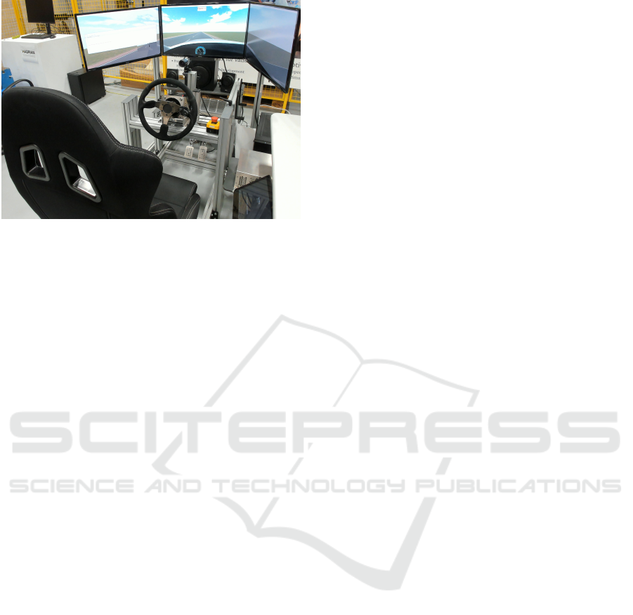
Figure 1: Simulator setup.
vehicle-driver shared control approaches, and inter-
action strategies. The haptic wheel setup is composed
of three elements: a wheel, a motor controller, and a
motor.
The servomotor is a brushless DC motor in which
a current sensor and an incremental encoder have
been attached. The actuator is a MiGE model 130ST,
which can exert a maximum torque of 18 Nm and pro-
vides 1.5 KW.
The racing steering wheel is a standard metal-
core and leather-cover steering wheel used in com-
mon driving simulators. Thanks to its metallic core
and it is tight fixation to the actuator, all vibrations
are directly transmitted to the hands of the driver. The
steering wheel includes a small Bluetooth 3.0 con-
troller fixed at the right spoke, allowing it to be used
with the right thumb. Its purpose is to change the driv-
ing mode from Automated to Manual modes (and vice
versa).
Finally, the motor controller is composed of a
Simucube motherboard, an IONI PROHC driver con-
trol unit with a maximum intensity of up to 25A, a
safety emergency button and all the necessary inter-
faces to connect it to the simulator computer.
3 DESIGN REQUIREMENTS FOR
THE DEVELOPMENT OF
HAPTIC MESSAGES
The setup will be considered as the basis for devel-
oping and evaluating haptic messages for the driver.
However, some requirements must be considered
when defining haptic feedback signals for steering
wheels.
The steering wheel is the lateral controller of the
vehicle. Modifying its dynamics through vibrations
can lead to potential control loss or deviations from
the vehicle trajectory. Steering wheels can be coupled
or uncoupled (Marcano et al., 2020a). If it is uncou-
pled (or drive-by-wire), there is no such constraint,
as vibrations do not necessarily need to be transmit-
ted to the movement of the wheels. If the steering is
coupled, however, safety issues must be considered,
among others.
From one side, haptic feedback should be felt in
the hands of the driver but must not affect the tra-
jectory of the vehicle. However, this goes against
the nature of the working principle of the electric-
driven steering wheel, as its movement is generated
through its shaft. Hence, haptic signals must be cen-
tered around zero, so that the net movement produced
by haptic vibrations is counterbalanced. This way, no
lateral deviation from the trajectory will be caused by
the haptic pattern.
From the other, haptic patterns in the steering
wheel must be distinguishable from vibrations in the
vehicle caused by road roughness. At the end of the
day, the steering wheel is by itself an interface to feel
the road. If haptic patterns may induce the driver to
think that there was a bump in the road, or to believe
that something happened to the tires, this could have
a degrading effect on the perception of the road and,
consequently, on vehicle control.
Regarding the functionality of the steering wheel,
haptic patterns should not block or reduce the driver’s
control over it. When a haptic signal is activated by
the system, the driver must be able to keep control-
ling the trajectory of the vehicle as if there was no
such signal. Thus, the haptic pattern must not only
be balanced around zero considering the entire pat-
tern but also in small intervals of time, so that there is
no torque applied in the steering wheel long enough
to change its trajectory or to be excessive to be over-
ridden by the driver.
In addition, regarding the durability of the system,
the haptic patterns must not damage the mechanical
components of the steering column. Vibrations are
a widely studied field of mechanics and can lead to
serious damage if they are not previously considered
(Rouillard, 2014). When tuning the frequencies of
the haptic patterns, natural frequencies of the system
must be avoided. In this work, this is not the main
focus, as a driving simulation environment is used.
Future works require a study case when the proposed
haptic patterns are brought to real vehicles.
Design Requirements for the Definition of Haptic Messages for Automated Driving Functionalities
173
4 DESIGN METHODOLOGY FOR
HAPTIC MESSAGES
Based on the requirements analyzed in the previous
section, in this one, the three main design strategies
followed to design the set of haptic messages pro-
posed in this work are defined.
4.1 Definition of Zero-centered Patterns
Regarding the zero-centered haptic patterns, in this
work, two types of patterns are proposed. On the one
side, oscillatory motion patterns. That is, haptic pat-
terns composed of sine-based vibrations. And on the
other side, short pulses that are felt like little strokes
on the steering. The latter also have the same positive
and negative component. This way, the total applied
torque of the actuator will produce a null amount of
work in both cases, generating no total displacement.
To achieve the desired haptic patterns, the actua-
tor must be capable of reproducing the desired pat-
tern properly. In addition, internal frictions and non-
linearities of the system may cause lateral displace-
ments. To evaluate these effects, the following exper-
iments have been performed.
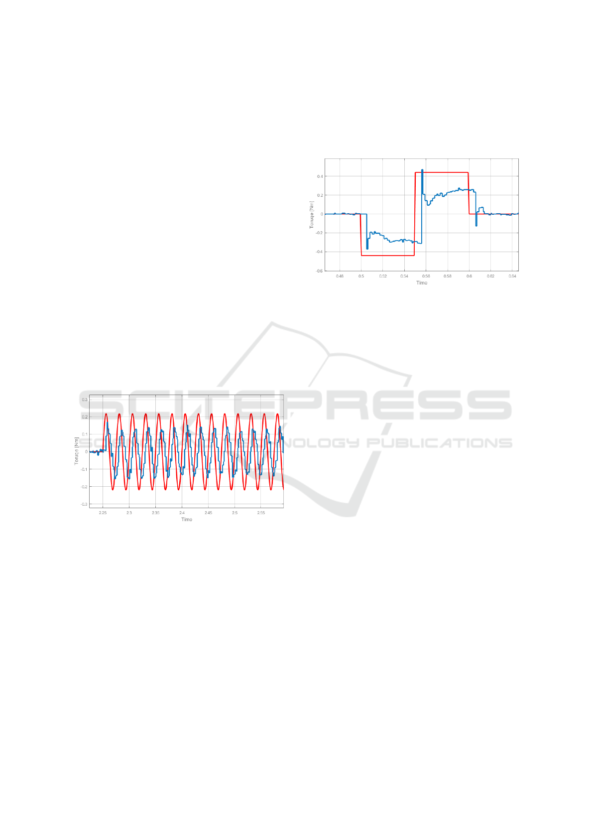
Figure 2: Torque response of the 1.5 s vibration (red-
reference /blue-response).
First, the response obtained when sending a torque
sine input in the steering wheel has been analyzed.
Fig. 2 shows the torque reference input in red and the
measured torque output in blue. Even if the measured
signal is slightly discretized, and there is a phase shift,
it can be observed that the response of the actuator
is capable of following the set input in terms of fre-
quency. Note that the main focus in this section is
the haptic feeling provided by the system. In addi-
tion, this figure shows the worst-case scenario, this
is, the response of the motor to the highest frequency
at the reference, which sets the maximum frequency
of the system (considering the simulated inertia and
damping are part of the measured net torque) at 40
Hz. Regarding the amplitude, a higher value does not
provide a difference in the output, as the torque out-
put of the actuator has a gradient saturation, meaning
that for such frequency, this is the highest value it will
reach.
Figure 3: Torque response of the pulse signal.
Second, pulse responses have been tested, as
shown in Figure 3. Similar to the previous case, the
haptic feeling of the reference can be executed by the
motor, as transitions (peak values), and then a con-
stant torque area, can be defined. Note that apart from
the reference torque sent, there are also the compo-
nents of the simulated damping and the inertia, which
are responsible for the transitory effects.
Hence, the aforementioned patterns (sine and
pulse) are appropriate to develop haptic messages in
the proposed setup.
4.2 Definition of Easily Distinguishable
Patterns
If vehicle vibrations and haptic patterns are consid-
ered, as previously stated, those two sources of infor-
mation must be distinguishable. Unfortunately, road
vibrations may not have a regular pattern, as sporadic
bumps or road roughness changes can cause unex-
pected vibrations in the vehicle. However, most com-
mon vibrations in vehicles are caused by the interac-
tion between the roughness of the road and the surface
of the tires.
Road roughness may be described as the elevation
profile obtained along the wheel tracks over which ve-
hicles pass. Such profiles fit the general category of
broad-band random signals. When passed by a ve-
hicle, its velocity determines the frequency at which
such profile will be collided, generating vibrations on
the wheels of the vehicle. Some studies (Rouillard,
2014) suggest that for a velocity range between 20
and 100 km/h, the predominant road vibration is be-
tween 1 and 10 Hz. But this is the vibration generated
in the floor of the vehicle, after being filtered by the
CHIRA 2022 - 6th International Conference on Computer-Human Interaction Research and Applications
174
damping of the vehicle. However, as (Agostinacchio
et al., 2013) shows, the vibrations generated by the
road roughness at driving speeds between 25 to 100
km/h, go up to 100 Hz and higher. And those are
the ones that are felt in the steering wheel in coupled
steering columns, as the system is in direct contact
with the vehicle tires. Indeed, this is easily demon-
strable just by taking a sound system and reproducing
signals increasingly between 30 and 200 Hz. The ob-
tained sound is equivalent to that heard while driving
a car.
In (Gillespie and Sayers, 1981), a study was per-
formed evaluating frequencies between 0 and 200 Hz.
There, it is shown that a frequency variation to be hap-
tically perceivable requires intervals of at least 10 Hz.
Thus, a couple of conclusions can be obtained from
here: first, having a 40 Hz upper limit established by
the actuator, there are few frequencies left to design
the haptic feedback patterns. And second, the haptic
feedback will be in the range of the typical vibrations
found in the vehicle steering.
For that reason, the approach to obtain some dis-
tinguishable haptic patterns will not be focused on
specific frequency ranges. Instead, 3 other variables
will need to be prioritized: first, the regularity of the
signal; second, the duration; and third, its amplitude.
As road vibrations have chaotic components, regu-
lar structured signals may provide a more trustworthy
feeling of their presence. Regarding the duration and
the amplitude, a balance between what is perceivable
and what is uncomfortable will need to be obtained.
4.3 Definition of Patterns to Reduce the
Effect on the Steering Wheel
As previously detailed, the applied haptic patterns
must not affect the drive. However, it could be consid-
ered that applying specific torques in the steering col-
umn could derive in deviations of the vehicle trajec-
tory and possible control lost. To check whether the
proposed haptic patterns could really affect the safety
of the drive, the following tests have been conducted.
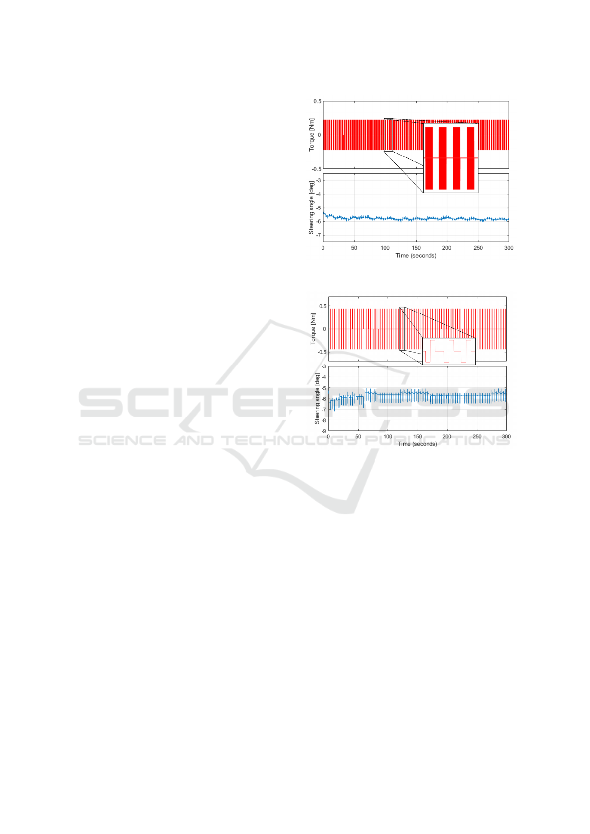
First, a sequence of equal sine waves (0.4 Nm of
amplitude, 40 Hz of frequency and 1.5 s of duration)
has been sent as input to the system repeatedly dur-
ing 300 s. The aim was to evaluate the angular dis-
placement generated on the steering wheel. Results
are shown in Fig 4.
Each of the repeated patterns zoomed in Figure 4
are equal to the ones presented in Figure 2. The aim of
Figure 4 is to show the total deviation of the steering
wheel after applying the haptic icon a repeated num-
ber of times (133 times in this case). After the test,
the total deviation of the steering wheel shown in the
Figure 4: Sequence of sine patterns and angular deviation
of the steering angle.
Figure 5: Sequence of pulse patterns and the angular devia-
tion of the steering wheel.
second graph of the layout is less than 1º.
This same test has also been conducted for the
other haptic pattern proposed, for the pulse (Figure 5).
Results show, with the same amount of repetitions, an
overall deviation of up to 2º. However, the instanta-
neous deviation of the steering angle is much higher
for the pulse than for the sine-based vibration. This is
because the amplitude achieved in the pulse is higher
than in the first pattern, and the pulses are longer in
time. To obtain a feeling about how potentially dan-
gerous these deviations could be, a theoretical and a
practical approach is proposed.
From the theoretical perspective, the effect of the
steering wheel on vehicle orientation can be calcu-
lated by a model, such as the bicycle model formula.
This is a stationary approximation, without consid-
ering the transitory damping effects of the tires that
could happen during the haptic pattern duration. The
equation goes as follows,
β = arctg(l
r
tan(δ)/L) (1)
Design Requirements for the Definition of Haptic Messages for Automated Driving Functionalities
175
where β is the slip angle, l
r
the distance between the
center of gravity of the vehicle to the rear axle, L the
distance between the rear and front axles, and δ the
front wheels angle. As δ is proportional to the steer-
ing wheel angle, it can be directly related the slip an-
gle with the steering wheel angle. The typical ratio
between δ and the steering wheel angle tends to be
around 15:1, meaning that a turn of 15º in the steering
wheel implies 1º in the tires.
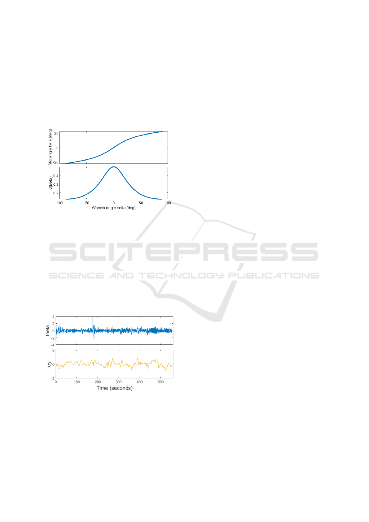
Figure 6: Graphic representation of the bicycle model for-
mula and its derivative.
Figure 6 shows the graphic representation of the
bicycle model. The maximum variation of the slip an-
gle is at the maximum point of its derivative, that is,
when δ is closer to zero. Thus, computing the calcula-
tion of the obtained 2º deviation for the pulse pattern,
a slip angle of 0.0667º is obtained. This implies that,
for instance, driving at a speed of 90 km/h (25m/s),
an instantaneous deviation caused by the haptic pulse
would deviate the trajectory of the vehicle 0.03m af-
ter one second. This is considering no damping of the
system nor the driver hands.
Figure 7: Steering wheel angle and lateral error recorded
during a 560 s drive in a straight line in the simulator.
From an experimental perspective, a 10-minute
ride has been tested in the simulator on a straight-
line highway to measure the periodic fluctuation of
a driver. As it can be seen in Figure 7, except for an
outlier in second 190, the rest of the drive is within
a range between -2 and 2 degrees. In the lower sub-
plot, the lateral deviation (in meters) is shown for the
lane center. Considering the mean frequency of the
driver making corrections, it is calculated that every
0.895 s a lateral correction cycle is performed. In
other words, the lateral oscillation of the driver is ap-
proximately around 1 Hz.
This implies that the maximum lateral deviation
caused by the haptic pattern would be inside the range
of a deviation of a generic ride. Thus, as long as the
driver has the hands on the steering wheel, the effect
on the drive is negligible.
Based on the aforementioned design strategies,
the following set of haptic messages have been pro-
posed for three main approaches: message notifica-
tion, take-over requests (TOR) and hand-over transi-
tions (Figure 8).
Message notification patterns are designed as
short, and mainly composed of pulses. They are
intended to provide quick, non-intrusive and non-
critical messages to the driver. That is, they are sup-
posed not to be urgent, but to catch the attention of
the driver easily.
TOR patterns are mainly composed of long vibra-
tions, whose amplitude increases in steps as the ur-
gency to take over the control increases. They are all
40 Hz in frequency and mainly last about 5 seconds.
They are supposed to increase the level of urgency
during the time, providing a countdown feeling.
Finally, the hand-over transition patterns are de-
signed in two different ways. The first four ap-
proaches are designed looking for a continuous in-
crease or decrease of the amplitude, while the rest-
ing four have a continuous change in frequency. This
duality has been proposed to prove that amplitude-
based transitions are more reliable than frequency-
based transitions, as frequency jumps are less notice-
able. Their design aim is that the driver receives a
transition feeling, as if something was switching on
and off.
This haptic set is defined so that the actuator sys-
tem proposed in the driving simulation environment
can reproduce the required vibrations to the driver.
However, note although the haptic steering wheel
can follow the defined haptic messages, user-centered
studies will be required to evaluate the acceptance and
effectiveness of the messages.
5 CONCLUSIONS AND FUTURE
WORKS
Haptic feedback on the steering wheel will be highly
beneficial in future ADAS, as there is a strong need
CHIRA 2022 - 6th International Conference on Computer-Human Interaction Research and Applications
176
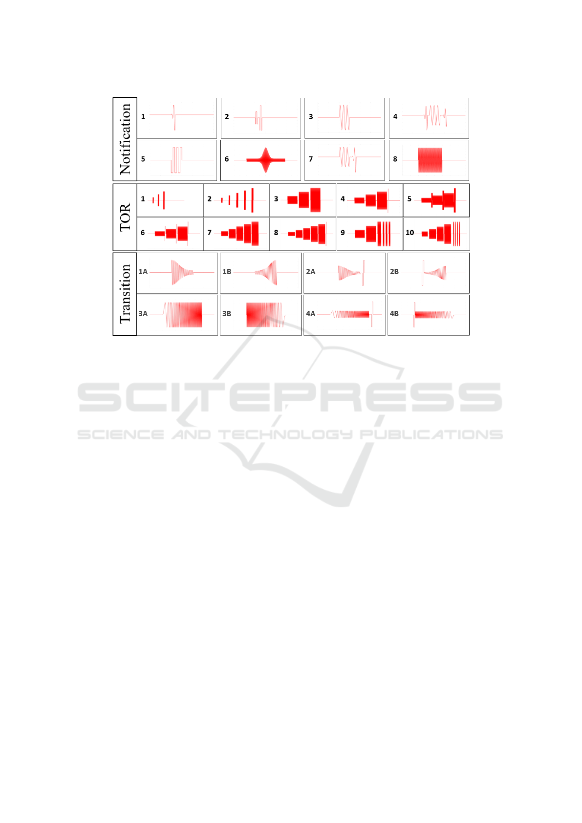
Figure 8: 1 to 8 icons: Message notification icons. 1 to 10 icons: Take-Over Request icons. 1A to 4B icons, hand-over
transition icons.
for safe critical interfaces that ensure rapid interven-
tion from the driver. Besides, haptic feedback will not
imply a safety issue regarding vehicle control, even in
the edgiest situations. Indeed, it will increase safety
by improving the interaction between the driver and
the vehicle and reducing driver workload. The main
contribution of this work is a new HMI concept, based
on a set of haptic messages for ADS, together with the
defined requirements for the implementation of safe
haptic messages.
The simulator shows how an off-the-shelf racing
steering wheel can work as a haptic feedback inter-
face, as it fulfills all the previously defined require-
ments. Some interactions with the haptic messages
show their potential for ADS specific cases. Never-
theless, user-centered tests will be needed to evaluate
and improve the proposed set of haptic patterns.
ACKNOWLEDGMENTS
This work is supported by the EU Commission
HADRIAN project and the Government of the
Basque Country by means of AUTOEV@L project
(KK-2021/00123). HADRIAN has received funding
from the European Union’s Horizon 2020 research
and innovation programme under grant agreement No
875597. This document reflects only the author’s
view, the Innovation and Networks Executive Agency
(INEA) is not responsible for any use that may be
made of the information it contains.
REFERENCES
The hadrian project. https://hadrianproject.eu/. Accessed:
2022-02-01.
Agostinacchio, M., Ciampa, D., and Olita, S. (2013). The
vibrations induced by surface irregularities in road
pavements-a Matlab ® approach.
Beruscha, F., Augsburg, K., and Manstetten, D. (2011). (9)
(PDF) Haptic warning signals at the steering wheel:
A literature survey regarding lane departure warning
systems.
Gillespie, T. D. and Sayers, M. (1981). Transportat
´
Ion Re-
search Record 836 15 Role of Road Roughness in Ve-
hicle Ride.
Harrison, N. R., Wuerger, S. M., and Meyer, G. F. (2010).
Reaction time facilitation for horizontally moving au-
ditory–visual stimuli. Journal of Vision, 10(14):16–
16.
Li, Y., Lv, C., and Xue, J. (2019). A novel predictive haptic
control interface for automation-to-human takeover of
automated vehicles. IEEE Intelligent Vehicles Sympo-
sium, Proceedings, 2019-June:994–999.
Lv, C., Wang, H., Cao, D., Zhao, Y., Sullman, M., Auger,
D. J., Brighton, J., Matthias, R., Skrypchuk, L., and
Mouzakitis, A. (2018). A Novel Control Framework
of Haptic Take-Over System for Automated Vehicles.
IEEE Intelligent Vehicles Symposium, Proceedings,
pages 1596–1601.
Design Requirements for the Definition of Haptic Messages for Automated Driving Functionalities
177

Marcano, M., DIaz, S., Perez, J., and Irigoyen, E. (2020a).
A Review of Shared Control for Automated Vehi-
cles: Theory and Applications. IEEE Transactions on
Human-Machine Systems, 50(6):475–491.
Marcano, M., DIaz, S., Perez, J., and Irigoyen, E. (2020b).
A Review of Shared Control for Automated Vehi-
cles: Theory and Applications. IEEE Transactions on
Human-Machine Systems, 50(6):475–491.
Marinik, A., Bishop, R., Fitchett, V., and NHTSA (2014).
Human factors evaluation of level 2 and level 3 auto-
mated driving concepts: Concepts of operation. Tech-
nical report, NHTSA, Washington DC.
Mehler, B., Brookhuis, K., Meteier, Q., Khaled, A. O.,
Capallera, M., Ruffieux, S., Angelini, L., Khaled,
O. A., Mugellini, E., Widmer, M., and Sondereg-
ger, A. (2021). Article 596038 (2021) classification
of drivers’ workload using physiological signals in
conditional automation. Frontiers in Psychology —
www.frontiersin.org, 12:596038.
Morales-Alvarez, W., Sipele, O., L
´
eberon, R., Tadjine,
H. H., and Olaverri-Monreal, C. (2020). Automated
driving: A literature review of the take over request in
conditional automation.
Mulder, M., Abbink, D. A., and Boer, E. R. (2008). The ef-
fect of haptic guidance on curve negotiation behavior
of young, experienced drivers. In 2008 IEEE Interna-
tional Conference on Systems, Man and Cybernetics,
pages 804–809.
Ploch, C. J., Bae, J. H., Ploch, C. C., Ju, W., and Cutkosky,
M. R. Comparing Haptic and Audio Navigation Cues
on the Road for Distracted Drivers with a Skin Stretch
Steering Wheel.
Politis, I., Brewster, S., and Pollick, F. (2015). Language-
based multimodal displays for the handover of con-
trol in autonomous cars. In Proceedings of the 7th
International Conference on Automotive User Inter-
faces and Interactive Vehicular Applications, Auto-
motiveUI ’15, page 3–10, New York, NY, USA. As-
sociation for Computing Machinery.
Rouillard, V. (2014). Quantifying the Non-stationarity of
Vehicle Vibrations with the Run Test. Packaging Tech-
nology and Science, 27(3):203–219.
Sasangohar, F. and Cummings, M. (2010). Human-system
interface complexity and opacity.
Shakeri, G., Ng, A., Williamson, J. H., and Brewster, S. A.
(2016). Evaluation of haptic patterns on a steering
wheel. AutomotiveUI 2016 - 8th International Con-
ference on Automotive User Interfaces and Interactive
Vehicular Applications, Proceedings, pages 129–136.
Strayer, D. L., Cooper, J. M., Goethe, R. M., Mccarty,
M. M., Getty, D. J., and Biondi, F. Assessing the vi-
sual and cognitive demands of in-vehicle information
systems.
Strayer, D. L., Drews, F. A., and Johnston, W. A. (2003).
Cell Phone-Induced Failures of Visual Attention Dur-
ing Simulated Driving. Journal of Experimental Psy-
chology: Applied, 9(1):23–32.
Talamonti, W., Tijerina, L., Blommer, M., Swaminathan,
R., Curry, R., and Ellis, R. D. (2017). Mirage events
& driver haptic steering alerts in a motion-base driving
simulator: A method for selecting an optimal HMI.
Applied Ergonomics, 65:90–104.
T
¨
ornros, J. E. and Bolling, A. K. (2005). Mobile phone use
- Effects of handheld and handsfree phones on driv-
ing performance. Accident Analysis and Prevention,
37(5):902–909.
Vito, P. D. C. S., Brown, E., Brewster, S., Pollick, F.,
Thompson, S., Skrypchuk, L., and Mouzakitis, A.
(2020). Haptic Feedback for the Transfer of Control in
Autonomous Vehicles. Adjunct Proceedings - 12th In-
ternational ACM Conference on Automotive User In-
terfaces and Interactive Vehicular Applications, Auto-
motiveUI 2020, pages 34–37.
Wang, Z., Zheng, R., Kaizuka, T., and Nakano, K. (2018).
Influence of haptic guidance on driving behaviour un-
der degraded visual feedback conditions. IET Intelli-
gent Transport Systems, 12(6):454–462.
Zhang, H. ., Zhang, Y. ., Xiao, Y. ., Wu, C., Xie, K., Ma, X.,
Zhang, H., Zhang, Y., Xiao, Y., and Wu, C. (2022).
Analyzing the Influencing Factors and Workload Vari-
ation of Takeover Behavior in Semi-Autonomous Ve-
hicles. International Journal of Environmental Re-
search and Public Health 2022, Vol. 19, Page 1834,
19(3):1834.
Ziebinski, A., Cupek, R., Grzechca, D., and Chruszczyk,
L. (2017). Review of advanced driver assistance
systems (ADAS). AIP Conference Proceedings,
1906(1):120002.
CHIRA 2022 - 6th International Conference on Computer-Human Interaction Research and Applications
178
