
TMRobot Series Toolbox: Interfacing Collaborative Robots with
MATLAB
João Lobato Pereira
1,2 a
, Mauro Queirós
1,2 b
, Nuno M. C. da Costa
2c
, S. Marcelino
6
,
José Meireles
3d
, Jaime C. Fonseca
2e
, António H. J. Moreira
4,5 f
and João Borges
2,5 g
1
University of Minho, Guimarães, Portugal
2
Algoritmi Center, University of Minho Guimarães, Portugal
3
MEtRICs Research Center, University of Minho, Guimarães, Portugal
4
2Ai – School of Technology, IPCA, Barcelos, Portugal
5
Polytechnic Institute of Cávado and Ave, Barcelos, Portugal
6
DIB4T, Marinha Grande, Portugal
Keywords: TMRobot, TM5_700, MATLAB, Individual Function, Class_TMRobot, Modbus TCP, Socket TCP/IP.
Abstract: As collaborative robots rise in popularity in industrial and domestic environments, TECHMAN Robot
developed the TMRobot series, a wide variety of smart, safe, and straightforward collaborative robots. This
paper presents the TMRobot Series Toolbox, which contains functions and methods to interface with the
TMRobot series cobots from an external device using MATLAB. By using these, the users have access to
connection, kinematic, point motion, set, get, and simulation functionalities which run on a remote computer
connected to the TMRobot controller via TCP/IP protocols. The toolbox is then validated with some
application examples.
1 INTRODUCTION
1.1 Motivation and Related Work
One of the significant changes that accompany the
implementation of the new concept of Industry 4.0 is
the use of collaborative robots (Poor & Basl, n.d.).
The most common industrial robots are large, heavy,
strong, and robust devices that work on very specific
tasks. Sensors, signals, and safety nets are installed
for safety reasons. According to relatively complex
programs, they are used to complete human tasks
while operating in a restricted area (Poór et al., 2019).
A collaborative robot or cobot is also an industrial
robot designed to cooperate with the human operator
to create value. These robots can perform different
tasks, such as picking up and inserting objects,
a
https://orcid.org/0000-0002-1053-7405
b
https://orcid.org/0000-0001-5896-7423
c
https://orcid.org/0000-0002-8425-3501
d
https://orcid.org/0000-0003-0881-2348
e
https://orcid.org/0000-0001-6703-3278
f
https://orcid.org/0000-0002-2148-9146
g
https://orcid.org/0000-0002-5880-033X
delivering parts to the operator, among others (Broum
& Šimon, n.d.).
In order to control a TM5_700 (TMRobot series),
one needs to have an external toolkit for
communication and control. TMRobot, unlike Kuka
(Safeea & Neto, 2019), Puma (Gil et al., 2015), and
Universal Robotics (Vivas & Sabater, 2021), does not
have one. As such, our motivation for this project was
to create ways to command and monitor this robot.
To support this project development Peter
Corke’s Robotics Toolbox is used, one of the most
popular MATLAB toolboxes in the field of robotics.
Peter Corke’s Toolbox includes functionalities for
robotic manipulators, such as homogeneous
transformations, direct and inverse kinematics, direct
and inverse dynamics, and trajectory generation
(Corke, 2017). Also, it is essential to mention the
Kuka Sunrise Toolbox (KST) project, where the
46
Pereira, J., Queirós, M., C. da Costa, N., Marcelino, S., Meireles, J., Fonseca, J., Moreira, A. and Borges, J.
TMRobot Series Toolbox: Interfacing Collaborative Robots with MATLAB.
DOI: 10.5220/0011526000003329
In Proceedings of the 3rd International Conference on Innovative Intelligent Industrial Production and Logistics (IN4PL 2022), pages 46-55
ISBN: 978-989-758-612-5; ISSN: 2184-9285
Copyright
c
2022 by SCITEPRESS – Science and Technology Publications, Lda. All rights reserved
authors, similarly to this project, developed more than
50 functions divided into six categories to interface
with the KUKA LBR iiwa manipulators—creating
the first Toolbox to interface with the KUKA
Sunrise.OS with functionalities like networking, real-
time control, point-to-point motion, setters, getters,
and physical interaction (Safeea & Neto, 2019).
1.1 Project Goals
The main goal of this project is to develop an easy-to-
use toolkit capable of interfacing with the TM5_700
collaborative robot. Since this specific robot shares
the same software and communication protocols with
the rest of the TM series cobots, the methods
developed can be used for every TMRobot, which is
already a significant advantage of the TMRobot
Series Toolbox. Other advantages are:
1) It takes the user away from having to learn a
new software associated with this robot’s
controller TMFlow;
2) Easy and fast interaction between the robot
and an external computer;
3) External sensors/devices are integrated into
the computer, and data are transmitted to/from
the robot via TCP/IP;
4) Complex applications can be included in the
external device allowing for more advanced
robot manipulation (i.e. machine learning,
vision);
5) Supplementing the robot’s system
functionalities with simulation capabilities.
The functions and methods within the package,
much like the KST toolbox, are divided into different
categories depending on their role: connection, setters,
getters, point motion, simulation, and gripper. A deep
study of the TMRobot manuals was required to define
which types of communication with external devices
were most suitable for the different functions
(Software Manual TMflow_ Software Version:
1.68_Document Version: 1.01 i Software Manual
TMflow Original Instruction Software Version: 1.68,
n.d.). With that, for the acquisition and manipulation
of robot parameters like joint values, end-effector
position, IO connectors, and others, the Modbus TCP
protocol was picked since, by extensive testing, it
turned out to be simpler and provide more
information. For the motion control of the robotic arm,
the socket TCP/IP transport protocol was used
alongside the robot’s external script protocol, which
defines the specific command exchange format
(Expression Editor and Listen Node Software Version:
1.80 Expression Editor and Listen Node, n.d.).
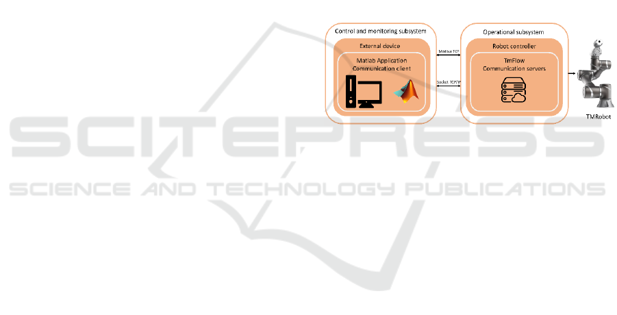
2 SYSTEM ARCHITECTURE
This project is composed of two main subsystems: the
operational subsystem, which incorporates the
TMRobot and its controller; and the control and
monitoring subsystem defined by the external device
and its properties. Figure 1 shows how these two
components interact. After deliberation and research
on projects with similar goals, we choose MATLAB
as the software to associate with the external device.
This is a tool that is in constant improvement. It is
flexible, versatile, and supports a variety of
communication protocols which represent an
essential requirement for this development.
MATLAB has been commonly used on a big scale in
the academic environment, so its high-level
programming structure is well-known, allowing users
with minimal experience to easily understand and
utilize this work.
Figure 1: System architecture and communication scheme.
2.1 Operational Subsystem: Robot
Controller
This subsystem is mainly responsible for interpreting
the commands and requests coming from the external
device, following the instructions on those
communication messages, moving the robotic arm to
the requested poses, sharing and setting different
parameters in the controller, and even confirming
connections and states of movements. For this to be
possible, some steps must be performed on the side of
the robot’s software TMFlow. As the scheme in
Figure 1 shows, to control the real robot to the extent
required, both Modbus TCP and SocketTCPListenner
servers need to be set up. To start the Modbus TCP
server, the user only needs to login into the TMFlow
software, open the settings menu, go to connection,
open the Modbus slave tab, select the communication
type, TCP, and enable the service.
To run the Socket server, it is required to create a
new project in the project tab and place the Listen
Node after the start block. Ensure the timeouts are set
to zero in the node properties and run that project.
Figure 2 shows this simple setup.
TMRobot Series Toolbox: Interfacing Collaborative Robots with MATLAB
47
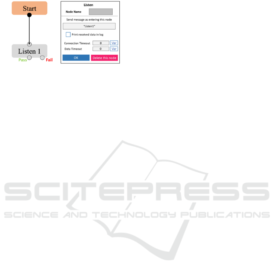
Figure 2: Setting SocketTCPListenner server.
2.2 Control and Monitoring
Subsystem: External Device
This subsystem is where the user executes all the
developed functions according to his tasks needs or
desired actions. The commands and requests
developed inside these functions were coded
according to the specific protocol format of the
TMRobot so that the user could control not only the
TM5_700 collaborative robot but also other TM
series robots. To create both Modbus TCP and Socket
clients, specific MATLAB toolboxes are required
(Modbus Communication - MATLAB & Simulink,
n.d.), (TCP/IP Communication - MATLAB &
Simulink, n.d.). Moreover, users must add to their
software the Industrial communication, the
Instrument control, the Optimization, and Peter
Corke’s Robotics toolboxes (Access MATLAB Add-
On Toolboxes - MATLAB & Simulink, n.d.).
This way it is possible to make the TMRobots
more accessible to a wide variety of people from
different backgrounds and open the door of
collaborative robotics for academic and educational
applications. This toolbox was made publicly
available (GitHub - Joaolobatopereira117/TMRobot-
Series-Toolbox, n.d.).
3 TOOLBOX FUNCTIONS
This section is divided into two parts that represent
different levels of the TMRobot Series Toolbox
usage. The individual function library is more
suitable for quick and simple tasks requiring a single
robot to accomplish the end goal. In contrast, the
Class_TMRobot, with its aggregated structure,
allows for a more complex task design with the
integration of several TMRobots controlled from the
same platform, which will be represented as different
class objects, each one with its organized properties
and methods. This structured approach is where this
toolbox differentiates from the KST toolbox.
3.1 Individual Function Library
In this section, implementation examples of some
functions are given so that the user can follow and
understand their functionalities better. For clearer
understanding, the functions are divided into eight
different categories:
1) Connection - Connection with the robot
controller;
2) Setters – Set parameters in the robot controller
(digital output, referential base);
3) Getters – Get parameters from the robot
controller (end-effector position and
orientation, joint angles, digital input and
output);
4) Point Motion – Point to point motion in joint
and cartesian space;
5) Gripper – Gripper control;
6) Kinematics – Forward and inverse kinematics;
7) Simulation – Manipulation and visualization
of the virtual model;
8) Test arm configuration – Test specific robot
poses in joint and cartesian space;
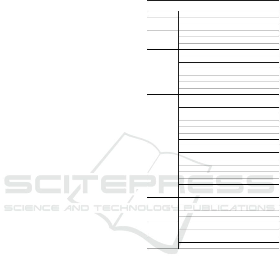
Table 1 aggregates all the individual functions
within each category and represents all the work done
in the first part of this section.
Connection:
In order to start controlling the robot, both the
external device and the controller must be physically
connected with the RJ45 ethernet cable in their
specific ports and the IP addresses in the same
network frame. With these conditions assured, the
user is ready to establish the connection using the
function
connect2controller(ip,socketport,modbusport),
where ip is a string with the IP address of the robot
and ports are the socket and Modbus communication
port, that by default are 502 and 5890, respectively.
The example below illustrates a connection.
>>ip=”192.168.0.111”;
>>socketport=5890;
>>modbusport=502;
>>[socketclient,modbusclient]=connect2c
ontroller(ip,socketport,modbusport);
This function returns both Modbus and socket
clients, which are meant to be used in the rest of the
library functions.
IN4PL 2022 - 3rd International Conference on Innovative Intelligent Industrial Production and Logistics
48
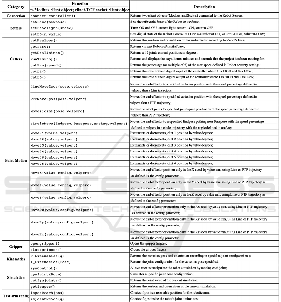
Table 1: List of all functions in the individual function library in TMRobot Series Toolbox.
Setters:
This category includes functions to set different
referential bases for the Robot base and to control
LED and digital output states. For example, to set a
new base:
>>newbase=[300 300 300 180 0 90];
>>setBase(socketclient,newbase);
To set the digital output five to a HIGH state:
>>setDO(modbusclient,5,1);
Getters:
These functions will allow users to monitor all kinds
of robot parameters, from the input-output (IO) states
to joint and cartesian positions. To illustrate the
acquisition of the current base and end-effector
position according to this new base:
TMRobot Series Toolbox: Interfacing Collaborative Robots with MATLAB
49
>>getBase(modbusclient);
ans
300 300 300 180 0 90
>>getRealpos(modbusclient);
Both these functions return a 1x6 cell array with
the [X Y Z Rx Ry Rz] values.
To get the state of digital input 2:
>>getDI(modbusclient,2);
ans
0
Point Motion:
This category allows users to move the robotic arm
from the current configuration/position to a final pose
through different types of trajectories (PTP, line, and
circle) with the desired speed percentage. In addition
to this, the user can move the end-effector through a
single axis or even actuate over one specific joint.
This next example moves the robot to the user
defined finalpos with 75% of the speed defined for
the project.
>>finalpos=[400 50 350 180 0 90];
>>vel_percent=75;
>>LineMove2pos(socketclient,finalpos,ve
l_percent);
To individually move the first joint plus 10
degrees with 100% speed, use the moveJ1 function
with the following parameters:
>>MoveJ1(socketclientmodbusclient,10,10
0)
Gripper:
The functions developed in this category are specific
to the 2FG7 Omron gripper, and some additional
blocks have to be added to the project in the TMFlow.
If the user has the same gripper properly installed, the
complete project folder is also available on the Github
page with the name ToolboxProj, so it is required to
download it, import it to the robot operational system
and run it. After that, the system is ready to interpret
both open and close actions:
>>opengripper(modbusclient,socketclient
);
>>closegripper(modbusclient,socketclien
t);
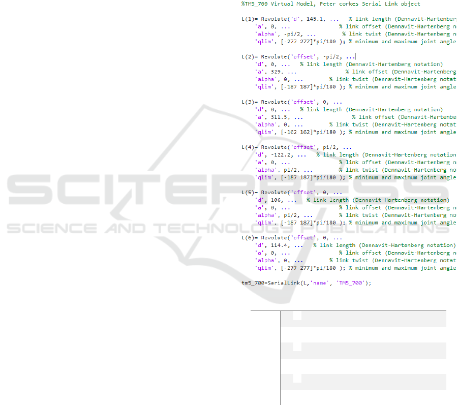
Kinematics:
By relying on the Peter Corke robotic toolbox for all
the virtual model related work, kinematic functions
are already defined and associated with the serial link
object, created with the portion of code bellow,
sym_model - virtual representation of the TMRobot to
control according to its Denavit Hartenberg
parameters Figure 3. So, it was just a matter of
shaping their inputs and outputs to the format that
suited this work.
Figure 3: TM5_700 Denavit Hartenberg parameters.
Users are free to use these functions, however
their purpose is to support other functions to test
specific pose configurations and to allow switching
between joint and Cartesian space, and vice-versa.
In the forward kinematic function, the user
defines a set of 6 joint values in degrees as a 1x6 array
Links Θº αº a mm d mm Offset
1 Θ
1
-90º 0 145.1 0º
2 Θ
2
0º 329 0 -90º
3 Θ
3
0º 311.5 0 0º
4 Θ
4
90º 0 -122.2 90º
5 Θ
5
90º 0 106 0º
6 Θ
6
0º 0 114.4 0º
IN4PL 2022 - 3rd International Conference on Innovative Intelligent Industrial Production and Logistics
50
cell and will be answered with the position and
orientation of the end-effector, [X Y Z Rx Ry Rz] in
mm and degrees. For the inverse kinematic, it is the
exact opposite:
>>F_Kinematics(sym_model,[0 0 0 0 0 0]);
>>I_Kinematics(sym_model,[0 -236.6
891.6 90 0 0]);
Simulation:
The functions in this category are meant to help users
visualize specific robot pose configurations, before
sending any definitive commands to the real robot.
The symControl(sym_model,q) function, based on
a method from the serial link class, allows for direct
manipulation of the virtual model. Moreover, when
users run this method, an interactive plot opens,
where they can change joint values and watch the
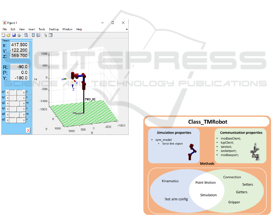
robot motion, as shown in Figure 4:
>>symControl(sym_model,[0 0 90 0 90 0]);
Figure 4: Interactive plot.
The user can then call getSympos() to obtain the
coordinates and orientation of the pose defined in the
plot:
>>getSympos(sym_model);
Test Arm Config:
Much like the kinematic methods, the two functions
in this category will support other functions, ensuring
the robot does not receive invalid joint target poses
and unreachable cartesian positions.
The isjointReach(sym_model,q) returns logical
value 1 if the joint values on the input q are inside the
joint limits defined on the model. The same happens
if the input position on isposReach(sym_model,pos)
obtains a successful output from the inverse
kinematics function used inside this method.
>>isjointReach(sym_model,[0 0 90 0 90
0]);
>>isposReach(sym_model,[300 10 50 0 0
0]);
3.2 Class_TMRobot
As mentioned before, this class originates not only
from the need to integrate both real and virtual
systems but also from the fact that many of the
functions developed before needed access to common
data. So, to optimize the TMRobot Series Toolbox,
we aggregate these functions into an organized
structure where their common inputs become its
properties, and all these functions are rearranged into
its methods.
Merging the system communication attributes
with the simulation model of the robot into the
Class_TMRobot creates advantages in integrating
different categories like Kinematics and Test arm
config with Point Motion methods. Access to all this
new information makes for improvements in some of
the old functions, mainly those responsible for arm
movement. Also, it enables access to functions that
allow the user to test the capacity of the robot to reach
certain arm positions, making sure the user cannot
send wrong target coordinates or joint poses to the
controller. Figure 5 demonstrates the composition and
organization of the whole class relating the method
categories with the type of property they require for
processing.
Figure 5: Class_TMRobot.
TMRobot Series Toolbox: Interfacing Collaborative Robots with MATLAB
51
Class Properties:
As illustrated above, these are divided into two types:
1) Simulation properties – sym_model, object from
serial link class;
2) Communication properties – modbusClient and
tcpClient are private properties that are only set
in the connect and disconnect methods, so users
cannot access them. The rest of the properties are
public and meant to be defined by users for their
specific robot, iprobot, socketport, and
modbusport.
Class Methods:
In this topic, implementation examples of the
constructor will be demonstrated since the rest of the
methods in the class come from the functions
developed before and are similar in usage and achieve
the same action within the physical world.
Constructor:
Before using all these methods, the user must be able
to represent his own robot as an object of this class.
For that, the object constructor
Class_TMRobot(varargin) is used. This function can
be called in many different ways:
>>TM5_700=Class_TMRobot();
In this example, the object created, TM5_700 has
its properties defined by default, where the
sym_model property is a serial link object created
based on the Denavit Hartenberg parameters of a
TM5_700 cobot. The iprobot, modbusport, and
socketport are defined as “192.168.0.111”, 502, and
5890, respectively.
>>TM5_700=Class_TMRobot(‘iprobot’,’192.
168.0.1’);
In this case, the object is created with the IP
“192.168.0.1,” and the rest of the properties remain
defined by default. It is advised to use this constructor
if the user is trying to control a TM5_700 because the
virtual model is already set. If, for example, the user
is using a TM12 or other type of TMRobot, just create
a serial link object with the correct DH parameters
and specify all the properties within the constructor:
>>TM5_700=Class_TMRobot(‘sym_model’,TM1
2Model,’iprobot’,’192.168.0.2’,’modbusp
ort’,503,’socketport’,5891);
Table 2 aggregates all the class methods within
each of their respective categories.
Table 2: List of all CLASS_TMROBOT Methods.
4 APPLICATION EXAMPLES
This section demonstrates some application examples
and different uses of the TMRobot Series Toolbox to
validate all the developed work.
1) Example 1: Development of a graphical user
interface called ControllerInterface, making
use of many setters, getters, gripper, and point
motion methods;
2) Example 2: Pick and Place task using both
individual function library and the
Class_TMRobot;
Connection
connect 2cont r ol l er _C( )
F_Ki nemat i cs_C( q)
I _Ki nemat i cs_C( Pose)
set Base_C( newbase)
set Headl i ght _C( st at e)
set DO_C( n, val ue)
get Real pos_C( )
get Base_C( )
getRealJoints_C()
RunTi mPr oj _C( )
get Pr oj speed_C( )
getDI_C()
get DO_C( )
Li neMove2pos_C( pose, vel per c)
PTPMove2pos_C( pose, vel per c)
Move2j oi nt _C( pose, vel per c)
ci r cl eMove_C( Endpose, Passpose, ar cAng, vel per c)
MoveJ1_C( val ue, vel per c)
MoveJ2_C( val ue, vel per c)
MoveJ3_C( val ue, vel per c)
MoveJ4_C( val ue, vel per c)
MoveJ5_C( val ue, vel per c)
MoveJ6_C( val ue, vel per c)
MoveX_C( val ue, conf i g, vel per c)
MoveY_C( val ue, conf i g, vel per c)
MoveZ_C( val ue, conf i g, vel per c)
MoveRx_C( val ue, conf i g, vel per c)
MoveRy_C( val ue, conf i g, vel per c)
MoveRz_C( val ue, conf i g, vel per c)
symCont r ol _C( )
symJoi nt _C( Pose)
get Symjoints_C()
get Sympos_C( )
opengr i pper _C( )
cl osegr i pper _C( )
i sposReach_C( pos)
i sj oi nt Reach_C( q)
Kinematics
Simulation
Test arm config
Class methods
Setters
Getters
Point Motion
Gripper
IN4PL 2022 - 3rd International Conference on Innovative Intelligent Industrial Production and Logistics
52
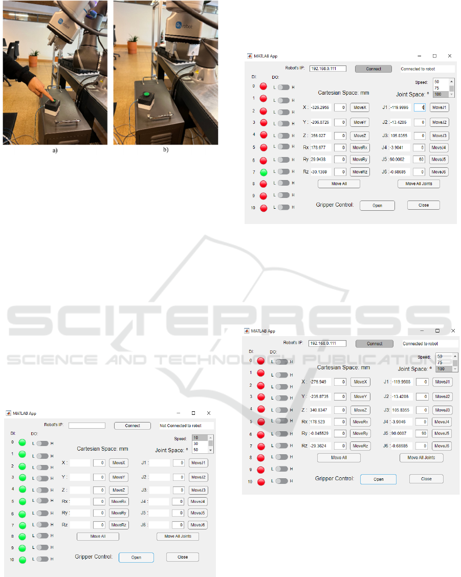
Figure 6: Different Robot states.
Figure 6 b) shows another robot state where the
button is not being pressed, joint five is set to 90
degrees, and the gripper is opened. Figure 9 shows the
app manipulation required to get to state b).
4.1 Example 1: Controller Interface
The goal with this example was to create a MATLAB
App that would support the user in designing different
tasks, in the way that he could manipulate the robot
with the simple click of a button and immediately
have at its disposal the positions, orientations and
joint configurations to then include these points on
the final motion process. Since the app required the
use of many methods, it turned out to be an excellent
way to validate the Class_TMRobot and its methods
interacting with each other. This example is included
in the TMRobot Series Toolbox repository with the
name ControllerInterface as shown in Figure 7.
Figure 7: GUI Controller Interface.
To establish a successful connection, one needs to
check if the project is running in the TMFlow and
proceed to define the robot’s IP address and set the
connect button ON. If users try to open the gripper,
move the robot, and others without establishing a
connection, the message “Not connected to robot”
will appear (Figure 7).
Figure 8: Interface connected to TM5-700.
Successfully connected to the controller in Figure 8,
we have all the parameter sections, Digital Input (DI),
Cartesian space, and Joint space, being updated in
real-time. The DI7 is activated since the button
connected to this pin is being pressed, joint five is set
to 60 degrees, and the gripper is closed (Figure 6 a).
Figure 9: Interface associated with Robot state b).
4.2 Example 2: Pick and Place Task
In this example, the goal was to build a pick and place
task only using the functions and methods from this
Toolbox.
For the test conditions of this example, we have
the components (pick site) on the left side of the table
and the PCB board on the right side (place site). The
goal is to fill the PCB with three of these components.
TMRobot Series Toolbox: Interfacing Collaborative Robots with MATLAB
53
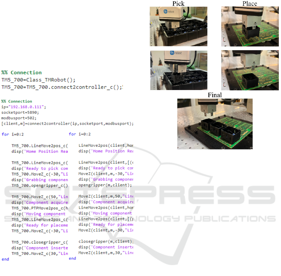
This simple task will be accomplished using both
the individual function library and the
Class_TMRobot, so the differences and similarities
can be highlighted.
The first process of finding the pick and place
positions is the same across both implementations.
The following portions of code illustrate the
differences between the two approaches when
developing a motion sequence.
Since the test performed is a simple task with only
one robot, the individual function library would be
suitable. However, if the goal was to control a real
assembly line with many robots working
simultaneously, the class becomes a more suitable
approach due to its structure and organization.
Even though the way these functions and methods
are implemented is different, their effect in the
physical world is exactly the same, and it makes for
the fact that the methods in the Class_TMRobot
integrate the individual functions. To finally validate
the proper behaviour of both approaches, the
movements have been recorded and illustrated in
Figure 10 where the PCB gets fully assembled.
Figure 10: PCB assembling.
5 CONCLUSION
In this article, we introduced the TMRobot Series
Toolbox to interface with the controller that equips
the collaborative TMRobot series, which have been
rising in popularity. These robots are being applied to
processes in assembling notebook computers and
servers and on automobile and flat panel display
production lines that many thought robots would have
a difficult time handling.
This Toolbox runs on an external computer
connected to the TMRobot controller via TCP/IP. We
presented features concerning connection, point
motion, setters and getters, gripper control, and
simulation functions. These features were extensively
tested and demonstrated reliability, versatility,
stability, and ease of use.
The TMRobot Series Toolbox is useful, not only
in teaching, since it allows for students to interact
with real collaborative robots through a familiar tool
that is MATLAB, but also in industrial environments
as it enables the integration of other hardware devices
as well as other methodologies and process control
techniques such as machine learning, data analysis
and artificial intelligence (AI). The performance of
the Toolbox was tested through two successful
application examples.
The future work basically relates to the
development of higher-level functions that allow for
IN4PL 2022 - 3rd International Conference on Innovative Intelligent Industrial Production and Logistics
54

more complex control for example, the integration of
machine learning methods for close loop control
maintaining the highest level of precision and
incorporation of the designed system into a Simulink
model.
ACKNOWLEDGEMENT
This work is co-funded by the European Regional
Development Fund (ERDF) through the Operational
Competitiveness and Internationalization Programme
(COMPETE 2020) of the Portugal 2020 Program
[Project No. 45070, " FlexASComp”; Funding
Reference: POCI-01-0247-FEDER-045070].
REFERENCES
Access MATLAB Add-On Toolboxes - MATLAB &
Simulink. (n.d.). Retrieved March 27, 2022, from
https://www.mathworks.com/help/thingspeak/matlab-
toolbox-access.html
Broum, T., & Šimon, M. (n.d.). Preparation of
Collaborative Robot Implementation in the Czech
Republic.
Corke, P. (2017). Robotics, Vision and Control -
Fundamental Algorithms In MATLAB® Second,
Completely Revised, Extended And Updated Edition.
Annals of Mathematics and Artificial Intelligence,
75(1–2), 693. https://www.springer.com/gp/book/9783
319544120
Expression Editor and Listen Node Software Version: 1.80
Expression Editor and Listen Node. (n.d.).
Gil, A., Reinoso, O., Marin, J. M., Paya, L., & Ruiz, J.
(2015). Development and deployment of a new robotics
toolbox for education. Computer Applications in
Engineering Education, 23(3), 443–454.
https://doi.org/10.1002/CAE.21615
GitHub - joaolobatopereira117/TMRobot-Series-Toolbox.
(n.d.). Retrieved April 13, 2022, from https://github.
com/joaolobatopereira117/TMRobot-Series-Toolbox
Modbus Communication - MATLAB & Simulink. (n.d.).
Retrieved March 24, 2022, from https://www.math
works.com/help/icomm/modbus.html?s_tid=CRUX_lf
tnav
Poor, P., & Basl, J. (n.d.). 29th Daaam International
Symposium On Intelligent Manufacturing And
Automation Czech Republic And Processes Of Industry
4.0 Implementation. 454–0459. https://doi.org/10.2507/
29th.daaam.proceedings.067
Poór, P., Broum, T., & Basl, J. (2019). Role of
Collaborative Robots in Industry 4.0 with Target on
Education in Industrial Engineering; Role of
Collaborative Robots in Industry 4.0 with Target on
Education in Industrial Engineering. https://doi.org/
10.1109/CRC.2019.00018
Safeea, M., & Neto, P. (2019). KUKA Sunrise Toolbox:
Interfacing Collaborative Robots With MATLAB;
KUKA Sunrise Toolbox: Interfacing Collaborative
Robots With MATLAB. https://doi.org/10.1109/MRA.
2018.2877776
Software Manual TMflow_ Software version:
1.68_Document version: 1.01 i Software Manual
TMflow Original Instruction Software Version: 1.68.
(n.d.).
TCP/IP Communication - MATLAB & Simulink. (n.d.).
Retrieved March 24, 2022, from https://www.math
works.com/help/matlab/tcpip-communication.html
Vivas, A., & Sabater, J. M. (2021). UR5 Robot
Manipulation using Matlab/Simulink and ROS. 2021
IEEE International Conference on Mechatronics and
Automation, ICMA 2021, 338–343. https://doi.org/
10.1109/ICMA52036.2021.9512650
TMRobot Series Toolbox: Interfacing Collaborative Robots with MATLAB
55
