
Novel Concept for a Mechanical Intraurethral
Artificial Urinary Sphincter
Alexander Preis
a
, Johannes Treviranus
b
, Elisabeth Benke
c
, Sebastian Reitelshöfer
d
and Jörg Franke
e
Institute for Factory Automation and Production Systems, Friedrich-Alexander-Universität Erlangen-Nürnberg,
Egerlandstraße 7, Erlangen, Germany
Keywords: Implant, Urinary Incontinence, Stress Incontinence, Artificial Urinary Sphincter, Intraurethral.
Abstract: Stress urinary incontinence is a common pathologic condition in society and an increasing socio-economic
challenge. Current artificial urinary sphincters for severe cases have high failure rates, cannot be applied sex-
independent and their handling is not intuitive. To address these issues, a novel intraurethral closure system
was developed. It works without an external energy supply and consists of an inflatable balloon that presses
against the inner contour of a surrounding cylindrical structure implanted in the urethra. Regulation of the
closure system is achieved by the interaction of the three main components: the closure balloon, the throttle
and the compensating reservoir. The developed closing mechanism seals the bladder at rest and during short
peak loads and opens only when the bladder pressure is increased by pressing with the abdominals for a longer
period of time for micturition.
1 INTRODUCTION
1.1 Urinary Incontinence
Urinary incontinence is a common pathologic
condition in society, which is defined as the
“involuntary leakage of urine” (Schmelz et al. 2014).
It is estimated that five to eight million people in
Germany and 50 to 200 million people worldwide
suffer from some form of urinary incontinence. An
exact number of those affected cannot be determined
since the tabooing of the subject is leading to an
avoidance of consultation, and thus a lack of acquired
data. (Sebsthilfeverband Inkontinenz e.V. 2013;
Niederstadt et al. 2007) Along with the physical
pathology, those affected experience a high level of
psychosocial stress and the costs for the national
health care systems are high (Milsom and Gyhagen
2019). This leads to socio-economic challenges in
addition to the medical ones (Yoo et al. 2020).
Urinary incontinence can be divided into stress,
a
https://orcid.org/0000-0003-3469-5982
b
https://orcid.org/0000-0002-3925-5356
c
https://orcid.org/0000-0002-6610-4430
d
https://orcid.org/0000-0002-4472-0208
e
https://orcid.org/0000-0003-0700-2028
mixed and urge incontinence. This publication’s
focus is on stress incontinence, which can be
distinguished from the other forms of urinary
incontinence both in its occurrence and in its causes
and treatment. It is defined by the involuntary leakage
of urine during load and without bladder contraction,
caused by an insufficient closure system.
(Sebsthilfeverband Inkontinenz e.V. 2013;
Niederstadt et al. 2007).
The main risk factor for the development of stress
incontinence is age. The connective tissue loses
tension in the later years of life and thus favors a
change in position of the bladder and urethra, so that
its closure is no longer guaranteed. In men, there is an
age-related increase in the size of the prostate, which
often necessitates surgery and can lead to the
postoperative occurrence of stress incontinence. In
the context of demographic change, an increase in the
number of people with stress incontinence is to be
expected, since the older part of the population is
growing steadily. Other causes are stresses on the
pelvic floor, such as those occurring during
170
Preis, A., Treviranus, J., Benke, E., Reitelshöfer, S. and Franke, J.
Novel Concept for a Mechanical Intraurethral Artificial Urinary Sphincter.
DOI: 10.5220/0010885700003123
In Proceedings of the 15th International Joint Conference on Biomedical Engineering Systems and Technologies (BIOSTEC 2022) - Volume 1: BIODEVICES, pages 170-176
ISBN: 978-989-758-552-4; ISSN: 2184-4305
Copyright
c
2022 by SCITEPRESS – Science and Technology Publications, Lda. All rights reserved

pregnancy and childbirth, but also as a result of
obesity. Due to the increasing number of obese people
in the population, a higher number of people suffering
from stress incontinence is also to be expected.
(Niederstadt et al. 2007; Bundeszentrale für politische
Bildung 2020; Radtke 2017; Gasser 2019)
1.2 State of the Art of Surgical
Therapy
The therapy of stress incontinence depends on the
severity. For mild forms, conservative and drug
therapy methods are used, while for more severe
degrees, surgical procedures are standard. The goal of
these procedures is mostly to reposition the urethra
and support the sphincter muscle. (Hamann et al.
2014; Manski 2020) Depending on the method, these
have very high efficacy rates, but at the same time
entail a risk of complications during the procedure
and during use. In women, the former standard is
colposuspension according to Burch, where the
success rate is around 90% after one year and 70%
after 10 years. Perioperative complications such as
bladder injury, hematoma, and wound healing
problems occur in 5-10% of treatments.
Colposuspension has mostly been replaced by
tension-free suburethral band surgery, for example
tension-free vaginal tape (TVT) surgery, which has a
90% success rate even 11 years after surgery.
Complications with this method are much less
frequent, mainly basal perforations (2-5%) and
retropubic bleeding and hematoma (0.5-1%) occur.
Implantation of the sling via the transobturator access
route (TOT), has slightly lower success rates (84%)
and muscular discomfort is more common, but there
are less complications regarding bladder voiding
dysfunction or bleeding. Sphincteric prostheses are
used only in cases of complete loss of sphincteric
function with subjective recovery rates of 59-88%.
However, this contrasts with revision surgery in 42%
of cases within 10 years and the risks of perioperative
complications such as injury to the urethra, bladder,
and rectum. (Hamann et al. 2014; Reisenauer et al.
2013)
In contrast to the surgical therapeutic methods for
women, the use of artificial sphincters is the gold
standard for male patients with a success rate of 80-
85%. However, a prerequisite is sufficient manual
dexterity of the patient. Revision rates of 30% occur
due to mechanical problems and complications such
as arrosion, infection, or urethral atrophy are present
in 7-17% of patients. Male sling systems have success
rates as high as 70% with complications including
local wound infections, urinary tract infections,
perineal discomfort, and bladder voiding dysfunction
(up to 21%). Success rates are not higher with
adjustable slings, but readjustment is necessary in
one-third of patients. Complications with adjustable
systems include perineal pain, wound infection, and
bladder injury. (Hamann et al. 2014; Bauer et al.
2014)
1.3 Advantages of a Mechanical
Intraurethral AUS
The development of a purely mechanical,
intraurethral closing mechanism is intended to
circumvent the first-mentioned disadvantages. The
closing mechanism can be controlled by bladder
pressure alone and thus be self-sufficient from
external energy sources. A rechargeable battery
mechanism, as well as a charging mechanism, which
draws energy internally or externally, occupies a
certain amount of space, which, however, is
anatomically limited. In addition, a mechanical
implant is expected to be less expensive than a
mechatronic variant, due to its lower complexity. The
intraurethral placement of the artificial sphincter also
results in a number of other advantages. For example,
the complex multi-cavity surgical procedure of the
current gold standard can be avoided and a simple
ambulatory implantation can be performed, resulting
in a reduced cost, time and risk of complications and
infection. In addition, the significantly smaller
installation space required allows a sex-independent
use, and control by bladder pressure enables the
intuitive and unobtrusive usage of the system.
2 MATERIALS AND METHODS
The relevant parameters include the pressures at the
various sites in the lower urinary tract and the
different phases of the micturition process. According
to the definition of the International Continence
Society (ICS), these are given in the unit cmH
2
O.
Measurement ranges of the pressures present are
mostly between 0-250 cmH
2
O. It should be noted that
the pressure is always measured against a zero value,
which corresponds to the ambient pressure, and that
the measurement height has a direct influence on the
measured value. Measured values such as filling
volume, bladder pressure and urethral pressure can be
recorded directly. Other values, such as the pressure
introduced from detrusor contraction, are determined
indirectly. (Schmelz et al. 2014; Schultz-Lampel et al.
2012) Thus, the detrusor pressure (p_det) is
calculated from the measured values of the abdominal
Novel Concept for a Mechanical Intraurethral Artificial Urinary Sphincter
171

pressure (p_abd) and the bladder pressure (p_ves) as
follows:
𝑝
= 𝑝
−𝑝
(1)
As the main function of an artificial urinary
sphincter is the sealing of the urethra at a certain
bladder pressure and for certain times, the following
criteria for the implant can be derived from the
urodynamic conditions:
• The flow of urine has to be interrupted at a
sustained 𝑝
below 50 cmH
2
O.
• If a 𝑝
above 50 cmH
2
O is lasting longer than
5 seconds, urine flow should be allowed.
• If a 𝑝
above 100 cmH
2
O occurs, urine flow
should be blocked for at least 1-2 seconds.
This means, that the implant should be
continuously closed up to a certain pressure and also
should stay closed for pressure peaks with a short
duration, which are for example caused by physical
events like coughing.
2.1 Design of the AUS
The novel concept (figure 1) presented in this paper
is based on a balloon sealing the urethra. Therefore, a
cylindrical, tubular casing is inserted into the urethra,
which does not allow urine to flow past it laterally.
Prior to implantation, the balloon located in the tube
body is filled with liquid and a suitable internal
pressure is set so that the balloon is pressed against
the wall of the tube. The balloon is connected via a
throttle to an elastic compensating reservoir, which
ensures that the closing pressure is maintained.
Figure 1: The concept for the artificial urinary sphincter
uses a pressurized balloon to block of urine flow.
If the bladder pressure increases, it presses against
the balloon and increases the pressure inside, so that
the liquid flows out of the balloon through the throttle
and into the compensating reservoir. This reduces the
volume of the balloon and allows urine to flow past
it. The throttle is used here to ensure that the sealing
effect only diminishes at longer pressures and that
short-term pressure peaks are not causing any
involuntary leakage.
2.2 Experimental Analysis
Following components and machines were used for
the experimental analysis of the concept:
• Balloons “Endo-Breezer” from servoprax GmbH
(Germany), as the main obstructive mechanism.
• Pressure sensors “MPX-4250DP” from NXP
Semiconductors (Netherlands), to measure the
bladder and balloon pressures.
• Inflator “Everest” from Medtronic (Ireland), to
control the fill volume of the balloons in the
submillilitre range.
• Material jetting printer “Agilista 3200W” from
Keyence (Japan), to manufacture the cylindrical
tube and auxiliary parts.
In a first experiment, the balloon properties are
recorded (figure 2 A). The expansion of the balloon
at a certain filling volume plays an important role,
since, depending on the filling volume, the balloon
material expands elastically, resulting in an additional
internal pressure. The aim of the experiment is to
determine the internal pressure of the balloon at free
expansion as a function of the filling volume. For this
purpose, the prepared balloon is connected to a
pressure sensor and to the inflator.
Figure 2: To analyze balloon behavior, two experimental
setups where used to test balloon pressure depending on fill
volume (A) and balloon pressure correlated to bladder
pressure and the systems leakage point (B).
As the bladder pressure increases, the balloons
internal pressure also increases. Since this
phenomenon is relevant for the closure system, it is
examined in more detail by the following experiment.
As an experimental setup, the balloon is placed in the
associated cylindrical tube. The balloon is connected
to a pressure sensor and the inflator. The proximal
end of the tube is connected to a second pressure
sensor and a device for applying the bladder pressure.
In the experimental procedure, the balloon pressure is
set to 100, 150, and 200 cmH
2
O, respectively. Now
the bladder pressure is increased in 10 cmH
2
O steps
up to a maximum pressure of 200 cmH
2
O. Each step
is held for 15 seconds to reduce measurement
deviations.
Next, for a given bladder pressure, it is
determined at which fill volume leakage of the
balloon
Compensating
reservoir
throttle
p
ves
cylindrical tube
balloon inflator
pressure sensor
balloon
inflator
pressure sensorpressure sensor
cylindrical tube
p
ves
application
AB
BIODEVICES 2022 - 15th International Conference on Biomedical Electronics and Devices
172
closure system occurs. The previous used setup is also
adopted for this experiment (figure 2 B). The balloon
is connected to the inflator and a pressure sensor. The
cylindrical tube containing the balloon is connected
to the device for applying the bladder pressure and the
second pressure sensor. The balloon is brought to a
pressure of 100, 150 and 200 cmH
2
O respectively and
a constant bladder pressure of 200 cmH
2
O is applied.
Now the balloons volume is decreased by removing
0.055 ml of fluid from the balloon step by step. Each
step is again paused for 15 seconds to reduce the
measurement error. The volume removal is continued
until water flows out through the closure system.
Lastly, the numerical simulation software
ANSYS Fluent is used to suitably design the throttle.
Here the influences of diameter and length of the
throttle, as well as the influence of the applied
pressure difference were analyzed.
3 EXPERIMENTAL RESULTS
Figure 3 shows the balloons internal pressure in
relation to the filling volume. It can be seen that the
balloons show a very strong increase in pressure
when they are filled for the first time, in contrast to
the subsequent filling processes. At the maximum
filled volume, the pressure values no longer deviate
so much. In reference tests after a 24 h waiting period,
this strong pressure increase is not observed. For all
filling processes except the first, the values fluctuate
within a certain tolerance range, with a standard
deviation of max. ± 38 cmH
2
O. The strong pressure
increase during the first filling can possibly be
explained by sticking and very strong relaxation of
the material during the first use after production. As a
result, it can be stated that the balloons used exhibit a
relatively constant expansion behavior.
Figure 3: The balloons internal pressure increases with fill
volume.
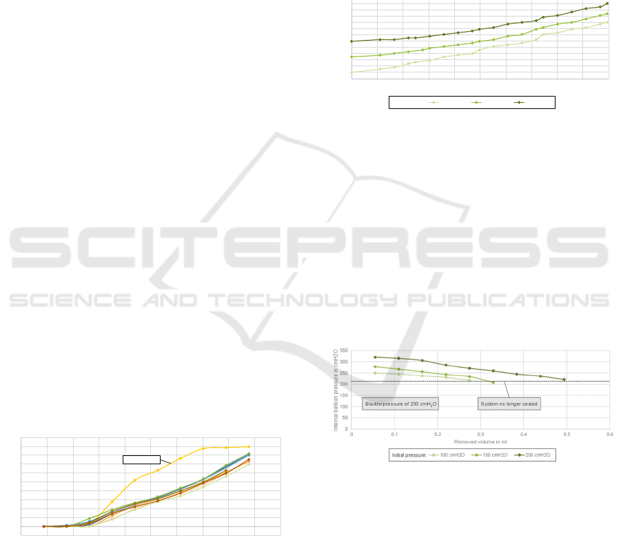
Figure 4 shows the influence of the bladder
pressure on the internal balloon pressure. It can be
seen that the balloon pressure increases differently
dependent on the initial pressure, which leads to a
decrease of pressure difference at higher bladder
pressures. From this experiment, it is evident that the
valve system is partially a self-amplifying system as
the bladder pressure is passed on to the balloons
internal pressure and thus pressing it against the outer
contour. However, the bladder pressure is not
completely transferred to the balloons internal
pressure. This is because the pressure distribution on
the proximal and distal sides is different and the
bladder pressure on the proximal side displaces
volume from the balloon to the distal side, where
there is no additional ambient pressure.
Figure 4: The balloons internal pressure increases with
bladder pressure.
The relation of balloon pressure and urine leakage
is shown in Figure 5. Here the removal volume in ml
is shown on the X-axis and the balloons internal
pressure in cmH
2
O on the Y-axis. The lowest value in
each test series represents the last internal balloon
pressure at which the system is still sealed at the
applied bladder pressure of 200 cmH
2
O. It can be seen
that a higher initial balloon pressure, which also
means a higher initial fill volume, leads to a larger
volume being able to be removed before the system is
not any longer sealed.
Figure 5: The removed volume needed to cause the leakage
of urine increases with initial internal balloon pressure.
The influence of the flow rate through the throttle
can be seen in Figure 6. As can be seen, the flow rate
increases with increasing throttle diameter and
pressure difference and decreases with increasing
throttle length. The simulation also shows, that the
throttle diameter is the most influential factor,
regarding this simple throttle, especially considering
the limited building space available.
-50
0
50
100
150
200
250
300
350
400
450
500
00.511.522.533.544.55
Internal balloon pressure in cmH2O
Fill volume in ml
First filling
80
100
120
140
160
180
200
220
240
260
280
300
320
0 20 40 60 80 100 120 140 160 180 200
Internal balloon pressure in cmH2O
Bladder pressure in cmH2O
100 cmH2O 150 cmH2O 200 cmH2O
Initial pressure:
Novel Concept for a Mechanical Intraurethral Artificial Urinary Sphincter
173
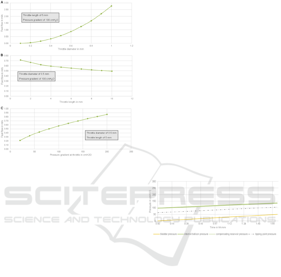
Figure 6: Fluid flow through the throttle increases with
diameter (A) and differential pressure (C) and decreases
with increasing throttle length (B).
4 DERIVATION OF THE SYSTEM
BEHAVIOR
Based on the previously conducted experiments, the
behavior of the overall system under three scenarios
relevant to the implants function is derived. The basic
state is the filling of the bladder over a longer period
of two hours up to a bladder pressure of 50 cmH
2
O.
The sudden load is defined as the occurrence of a peak
in bladder pressure with a maximum value of 200
cmH
2
O over a period of two seconds. The final
scenario examined is the voluntary micturition, in
which bladder pressure increases to 100 cmH
2
O with
the patient pressing and is maintained until the
bladder is completely emptied. Figures 7 to 9 show
the pressure curves for these three scenarios. In each
case, the curve of bladder pressure, internal balloon
pressure, and internal pressure of the compensating
reservoir are plotted over the appropriate time axis for
the corresponding scenario. Based on bladder
pressure, the dashed line indicates the leakage point
at which the balloons internal pressure is low enough
to cause the closure system to leak. This leakage point
is calculated using the formula:
𝑝
𝑡𝑖𝑝𝑝𝑖𝑛𝑔 𝑝𝑜𝑖𝑛𝑡
= 0,849 ∗ 𝑝
𝑣𝑒𝑠
62,85
(2)
The experiments showed, that the internal balloon
pressure is influenced by the bladder pressure. An
internal pressure of 100 cmH
2
O in the balloon is set
as the starting pressure to close the closure system in
the basic state. The direct influence of the bladder
pressure on the balloons internal pressure is
calculated using the formula:
𝑝
𝑏𝑎𝑙𝑙𝑜𝑜𝑛
= 0,774 ∗ 𝑝
𝑣𝑒𝑠
98,567
(3)
For the basic state, a bladder pressure of 0 cmH
2
O
at the beginning is assumed, which increases to 50
cmH
2
O over the duration of two hours. Accordingly,
the balloons internal pressure is set to 100 cmH
2
O at
the beginning and increases to 137 cmH
2
O. The
calculated leakage point is not undershot at any time,
which means that the sealing of the system can be
assumed. The pressure increase in the balloon causes
a pressure difference between the balloon and the
equalizing body, which is balanced by the flow of
fluid out of the balloon and into the compensating
reservoir. Due to the throttle, the pressure in the
equalizing body rises with a slight delay in relation to
the pressure inside the balloon.
Figure 7: The model shows, that the closure system stays
sealed during the filling phase of the bladder.
During the sudden load, the bladder pressure
increases abruptly from 20 to 200 cmH
2
O for the
duration of two seconds and then drops again to 20
cmH
2
O. Both, internal balloon pressure and leakage
point can be calculated using the formulas 2 and 3
presented before. When the bladder pressure
increases to 200 cmH
2
O, the balloons internal
pressure also increases from 114 to 253 cmH
2
O. Due
to the throttle, the system is quasi blocked at first, so
that there is a pressure difference of 253 cmH
2
O in
the balloon to 114 cmH
2
O in the compensating
reservoir occurring, which leads to a fluid flow from
the balloon into it. Derived from the previous
experiments, in order to reach the leakage point, of
233 cmH
2
O, a volume of 0.22 ml has to flow into the
compensating reservoir. The simulation shows that a
throttle with a diameter of 0.3 mm and a length of 5
mm is sufficient to prevent the balloons internal
BIODEVICES 2022 - 15th International Conference on Biomedical Electronics and Devices
174
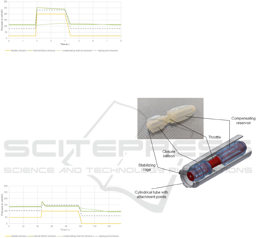
pressure from dropping below the leakage point for
about two seconds, thus ensuring the sealing of the
closure system. Following the load, the system
returns to its initial state.
Figure 8: It is shown, that the closure system stays sealed
for at least two seconds, when high sudden loads occur.
During micturition, the bladder pressure is
increased from 50 to 100 cmH
2
O by active abdominal
pressing of the patient. The balloons internal pressure
thus increases to 175 cmH
2
O, which, with a leakage
point of 148 cmH
2
O, results in a volume of about 0.4
ml needed to flow into the compensating reservoir. At
a flow rate of 0.06 ml/s through the throttle described
above, this corresponds to a duration of about 7
seconds. After a sufficient drop in internal balloon
pressure, micturition occurs, at the end of which the
bladder pressure drops again to 0 cmH
2
O. The
pressure gradient between the balloon and the
compensating body is reversed, so that fluid flows
back into the balloon and the initial state with an
internal balloon pressure of 100 cmH
2
O is re-
established.
Figure 9: Through active pressing for at least seven
seconds, the closure system can be opened and the
micturition can be conducted.
5 SUMMARY AND OUTLOOK
The aim of this work was to develop a concept for a
closing mechanism that functions autonomously
without external energy generation or supply. For this
purpose, the relevant requirements for the mechanical
closing mechanism were analyzed. Based on the
conducted experiments and derived models an
advanced functional concept for the closing
mechanism was developed, shown in Figure 10. The
closure system consists of an inflatable balloon that
presses against the inner contour of an outer cylinder.
Regulation is achieved by the interaction of the three
main components, the closure balloon, the throttle
and the compensating reservoir. The presented
closing mechanism fulfills the requirements placed
on the implant, sealing the bladder at rest and during
short peak loads and opening only when the bladder
pressure is increased by pressing with the abdominals
for a longer period of time for micturition.
Particularly advantageous for this mechanism is the
simple design and the low number of components,
which means that a high reliability can be expected
due to the limited interfaces between the different
components. In addition, the low number of
components has an advantageous effect on the
expected manufacturing costs.
Figure 10: Resulting prototype of the artificial urinary
sphincter based on the data acquired and models derived
from the presented experiments.
In the case of the individual functional elements,
there is potential for optimization and a number of
properties that require further investigation. For the
balloons, a better sealing effect can be produced by
changing the basic geometry. The shape and material
thickness can be used to control the behavior of the
balloon more precisely. Here especially the
investigation of different fabrication strategies for the
balloons should be conducted, since the currently
applied method does not provide consistent results. In
addition, it is necessary to investigate how the
balloons behave over a longer period of time. In the
case of the outer cylinder, which is also part of the
closing system, different geometries need to be
investigated. Additionally, the installation space for
Novel Concept for a Mechanical Intraurethral Artificial Urinary Sphincter
175

the throttle can be reduced by using different throttle
shapes, e.g. with inserted flow obstacles or by
introducing a low-viscosity fluid instead of water,
thus changing the flow properties. For the
compensating reservoir, the pressure-volume
characteristic needs to be optimized to allow a better
control of the system behavior. In addition, further
investigations into the behavior of the overall system
are necessary, as the long-term stability of the implant
in contact with urine has not yet been investigated and
the question of whether complete voiding of the
bladder is possible with this concept has not yet been
clarified.
REFERENCES
Bauer, R. M.; Hampel, C.; Haferkamp, A.; Höfner, K.;
Hübner, W. (2014): Diagnostik und Operative Therapie
der Postprostatektomie- Belastungsinkontinenz. In Der
Urologe (53), pp. 847–853.
Bundeszentrale für politische Bildung (2020):
Demografischer Wandel. Edited by Bundeszentrale für
politische Bildung. Available online at
https://www.bpb.de/nachschlagen/zahlen-und-
fakten/soziale-situation-in-
deutschland/147368/themengrafikdemografischer-
wandel, checked on 6/11/2021.
Gasser, T. (2019): Basiswissen Urologie. 7. Auflage 2019.
Berlin: Springer Berlin (Springer-Lehrbuch). Available
online at http://www.springer.com/.
Hamann, M.; Naumann, C.; Knüpfer, S.; Jünemann, K. P.;
Bauer, R. (2014): Urogynäkologie II: Harninkontinenz
bei Mann und Frau. In Der Urologe (53), pp. 1671–
1682. Available online at https://doi.org/10.1007/
s00120-014-3607-0, checked on 5/19/2021.
Manski, D. (2020): Urologielehrbuch.de. Ausgabe 2020,
15., aktualisierte Auflage.
Milsom, I.; Gyhagen, M. (2019): The prevalence of urinary
incontinence. In Climacteric: the journal of the
International Menopause Society 22 (3), pp. 217–222.
DOI: 10.1080/13697137.2018.1543263.
Niederstadt, C.; Gaber, E.; Füsgen, I. (2007):
Harninkontinenz. Berlin: Robert-Koch-Inst
(Gesundheitsberichterstattung des Bundes, 39).
Available online at http://nbn-resolving.de/urn:nbn:
de:0257-1002199.
Radtke, R. (2017): Anteil der Erwachsenen mit
Fettleibigkeit in ausgewählten OECD-Ländern im
Zeitraum der Jahre 1990 bis 2015. Edited by Statista.
Available online at https://de.statista.com/
statistik/daten/studie/153908/umfrage/fettleibigkeit-
unter-erwachsenen-in-oecd-laendern/, checked on
6/11/2021.
Reisenauer, C.; Muche-Borowski, C.; Anthuber, C.; Finas,
D.; Fink, T. (2013): Interdisziplinäre S2e-Leitlinie für
die Diagnostik und Therapie der Belastungsinkontinenz
der Frau.
Schmelz, H. U.; Sparwasser, C.; Weidner, W. (2014):
Facharztwissen Urologie. Differenzierte Diagnostik
und Therapie. 3. Aufl. Berlin: Springer. Available
online at http://gbv.eblib.com/patron/FullRecord.a
spx?p=1965530.
Schultz-Lampel, D.; Goepel, M.; Haferkamp, A. (2012):
Urodynamik. Akademie der Deutschen Urologen. 3.
Aufl. s.l.: Springer-Verlag. Available online at
http://search.ebscohost.com/login.aspx?direct=true&sc
ope=site&db=nlebk&db=nlabk&AN=510482.
Sebsthilfeverband Inkontinenz e.V. (2013): Einige Zahlen
zur Inkontinenz. Edited by Sebsthilfeverband
Inkontinenz e.V. Available online at https://www.selbst
hilfeverband-
inkontinenz.org/svi_suite/svisuite/inkontinenz-zahlen-
fakten.php, updated on 12/21/2013, checked on
5/22/2021.
Yoo, I. S.; Preis, A.; Franke, J. (2020): Development of a
test bench for the urodynamic simulation of the lower
urinary tract
*
. DOI: 10.1109/EMBC44109.2020.917
6198.
BIODEVICES 2022 - 15th International Conference on Biomedical Electronics and Devices
176
