
Pan-zoom Motion Capture in Wide Scenes using Panoramic Background
Masanobu Yamamoto
Department of Information Engineering, Niigata University, Niigata, Japan
Keywords:
Multi-view Videos, Panoramic Background Image, Pan and Zoom, 3D Motion, Tracking.
Abstract:
Measuring a subject three-dimensionally from multiple cameras, the measurable area is a common field of
view from cameras. When the subject goes out of the field of view, the cameras must follow the subject. In
this research, the viewpoint of the camera keeps to be fixed and the pan and zoom functions are used to operate
the cameras so that the subject body could be always shot near the center of the image. The problem is camera
calibration. Our approach is to use a panoramic image. Each camera pans in advance to take a background
image and create a panoramic image of the background. Then, the background image around the subject body
is collated with the panoramic image, the pan rotation angle and the zoom ratio are obtained from the matching
position, and the camera is calibrated. The body motion is captured from the multi-view motion image using
the camera parameters obtained in this way. Since the viewpoint of the camera is fixed, the shooting range is
not so wide, but it is still possible to capture an athlete’s floor exercise in the gymnasium.
1 INTRODUCTION
Motion capture from video image does not constrain
the subject’s body and natural movement can be mea-
sured without giving the subject the consciousness of
being measured. It is possible to measure the 3D
movement of the body from an even single camera
view, but it is a guess rather than a measurement be-
cause the depth information is missing. By using the
image from the multi-view cameras, it is possible to
accurately measure the 3D movement of the body.
When measuring the 3D movement by multiple
cameras, the measurable area is only the common
field of view from cameras. For example, at the Fig.1
(a), the common field of view from the four cameras
is shown by the gray area. To measure even if a person
goes out of this area, one can pan the camera as shown
in the Fig.1 (b). However, if the body gets too close
to the camera, a part of the body will be out of sight.
Also, as the body goes away from the camera, the ap-
parent size becomes smaller and the resolution of the
body image becomes lower. Therefore, by adding a
zoom to the pan, the imaging range can be further ex-
panded as shown at the Fig.1 (c).
The problem here is a camera calibration. If the
camera is fixed, it is sufficient to present the cali-
bration object only once within the common field of
view. Otherwise, it is not possible to place the cali-
bration object during pan and zoom. Our idea is to
(a)
(b)
(c)
Figure 1: Common field of view (gray area). (a) Fixed cam-
eras, (b) Pan cameras, (c) Pan-zoom cameras.
use a panoramic image of the background. Therefore,
each camera is pan-rotated in advance to take a back-
ground image and create a panoramic image of the
background. When capturing motion, let’s pan and
zoom the cameras so that the body could be always
shot near the center of the image. Then, the back-
ground image around the body is collated with the
panoramic image, and the pan rotation angle and the
zoom ratio can be obtained from the matching posi-
tion. The movement of the body is captured from the
multi-view videos using the camera parameters ob-
tained in this way.
Yamamoto, M.
Pan-zoom Motion Capture in Wide Scenes using Panoramic Background.
DOI: 10.5220/0010815600003124
In Proceedings of the 17th International Joint Conference on Computer Vision, Imaging and Computer Graphics Theory and Applications (VISIGRAPP 2022) - Volume 1: GRAPP, pages
163-171
ISBN: 978-989-758-555-5; ISSN: 2184-4321
Copyright
c
2022 by SCITEPRESS – Science and Technology Publications, Lda. All rights reser ved
163

2 RELATED WORKS
Motion capture from multi-view cameras began in the
late 1990s. (Sundaresan and Chellappa, 2005) re-
views on motion capture from multi-view video im-
ages up to around 2005.
While multi-view cameras can measure accurate
3D positions, they can only measure in common field
of view between cameras. Increasing the number of
cameras is one solution (Joo et al., 2015), but it needs
a high cost of entire facility. Therefore, the camera
had better be made to follow the movement of the
body. (Rhodin et al., 2016) attached a stereo cam-
era to the head and measured the movement of the
body below the neck. Since the camera moves with
a person, the measurement range is not limited to the
movement of the person. However, although the rel-
ative movement of the body part with respect to the
root of the body can be recovered, the movement of
the root is the movement with respect to the camera
coordinate system, not the movement with respect to
the world coordinate system. The camera in motion
should be calibrated in the world coordinate system.
If the camera moves a lot, it is effective to use ex-
ternal sensors such as IMU and/or GPS (Xu et al.,
2016; Nageli et al., 2018; Saini et al., 2019). The
use of external sensors is effective (Kurihara et al.,
2002; Ukita and Matsuyama, 2005) even when the
viewpoint of the camera is fixed as in our research. In
such case, a camera calibration is possible just from
the background image without any external sensors.
In fact, many PTZ camera self-calibration techniques
(Shum and Szeliski, 2000; Sinha and Pollefeys, 2006;
Wu and Radke, 2013) have been proposed to create
accurate background panoramic images. However,
in the motion capture, the self-calibration techniques
cannot be used because the background image con-
tains a body image. Therefore, we decide to create a
panoramic image of the background in advance and
calibrate the camera by matching the panoramic im-
age with the image including the body. The idea of
using a panoramic image for calibration can be found
in (Cannelle et al., 2010), but it’s just a simulation.
This paper treats two types of image matching.
One is when detecting the overlap in the image se-
quence obtained by pan rotation to make a panoramic
image. Another is when the background of the body
image is collated with the panoramic image. In the
early days, matching was performed based on the im-
age intensity (Shum and Szeliski, 2000), but since
SIFT (Lowe, 2004), feature-based matching has be-
come popular. Initially, we used SURF (Bay et al.,
2008), but switched to KAZE (Alcantarilla et al.,
2012), which can maintain the boundary of the area
more clearly. Furthermore, AKAZE (Alcantarilla
et al., 2013) is currently used to improve the calcu-
lation speed.
3 PANORAMIC BACKGROUND
Let’s show a cylindrical panorama, which is an ease
of construction (Shum and Szeliski, 2000) and is suf-
ficient for our motion capture use.
3.1 Camera Coordinate System
We show a perspective camera model and a cylindri-
cal coordinate system that projects all directions.
3.1.1 A Perspective Camera Model
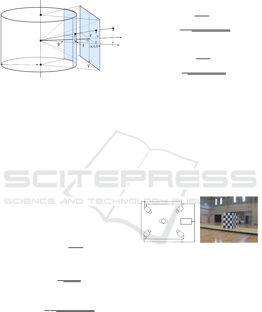
Let O : X,Y,Z be an orthogonal coordinate system
(see Fig.2), in which O is the projection center, the
Z axis is an optical axis, and the projection plane is
placed at the position f on the optical axis. The plane
is perpendicular to the optical axis. Let the intersec-
tion of the plane and the optical axis be the origin of
the projection plane coordinates o : x,y. The 3D posi-
tion (X,Y, Z)
T
in space is projected onto the 2D posi-
tion (x,y)
T
of the projection plane as follows,
x = f
X
Z
y = f
Y
Z
(1)
Let the image coordinates on the projection plane
be (u,v), the origin of the projection plane be (u
0
,v
0
),
and the 2D scale transformations from the projection
plane coordinate axes to the image plane coordinate
axes be k
u
and k
v
, respectively. The relationship be-
tween both coordinates is
u = k
u
x+ u
0
v = k
v
y+ v
0
(2)
3.1.2 Cylindrical Camera Model
The perspective camera has a limited field of view,
while a cylindrical camera can shoot omnidirectional
scenes. The cylindrical camera assumes to share the
projection center with the perspective camera, and
sets a cylinder whose axis is a straight line passing
through the projection center and is perpendicular to
the optical axis as the projection surface. The point
at which the line of sight from this projection cen-
ter to the point in the scene intersects the cylindrical
surface is defined as the projection point. Unfolding
GRAPP 2022 - 17th International Conference on Computer Graphics Theory and Applications
164
Cylinder axis
Projection center
Opt.axis
Y
Z
x
d
Y
h
(X,0,Z)
Line of sight
O
(X,Y,Z)
Figure 2: Perspective and cylindrical projections. Assum-
ing that both share a viewpoint.
this cylindrical surface, all points in the scene are pro-
jected on the 2D image.
Since the perspective camera cuts out a part of the
entire circumference, it is necessary to concatenate
many perspective projecting images in order to obtain
a cylindrical image of the entire circumference. At
this time, each perspective projection image is trans-
formed into a cylindrical image and pasted together
on the cylinder
Let the radius of the cylinder be d (see Fig.2), and
the length of the arc in the circumferential direction
starting from the intersection of the YZ plane and the
cylinder be l. Let the height in the direction of the
cylinder axis starting from the intersection of the XZ
plane and the cylinder be h, and (l,h) be the coordi-
nates of the cylinder surface.
Let consider the projection of the line of sight see-
ing the 3D point (X,Y, Z)
T
onto the XZ plane. If the
angle between the projection of the line of sight and
the optical axis is θ, the arc length is l = dθ. Also,
since θ = tan
−1
x/ f, from the eq.(2), we have
l = d tan
−1
u−u
0
k
u
f
(3)
On the other hand, considering a sector con-
structed from the line of sight and its projection,
h = d
y
p
x
2
+ f
2
Substituting the eq.(2) onto it, we have
h = d
k
u
k
v
v−v
0
p
(u−u
0
)
2
+ k
2
u
f
2
(4)
Furthermore, let’s transform the cylindrical sur-
face (l, h) into an unfolded image plane (r,s). If the
origin of the cylindrical surface is (r
0
,s
0
) on the im-
age plane and the transformation scale of each coor-
dinate axis is k
r
and k
s
, the transformation is
r = k
r
d tan
−1
u−u
0
k
u
f
+ r
0
s = k
s
d
k
u
k
v
v−v
0
p
(u−u
0
)
2
+ k
2
u
f
2
+ s
0
(5)
Let d = 1, k
r
= k
u
, k
s
= k
v
, we have
r = k
u
tan
−1
u−u
0
k
u
f
+ r
0
s = k
u
v−v
0
p
(u−u
0
)
2
+ k
2
u
f
2
+ s
0
(6)
where f, k
u
, k
v
, u
0
and v
0
are internal parameters of
the perspective camera and can be obtained by camera
calibration. The r
0
and s
0
are the paste positions on
the unfolded image plane. The calibration method for
camera in motion will be described later.
3.2 Shooting Environment
Video images are shot with four video cameras
(CANON, XH-G1) at the four corners on the floor.
Fig.3 left shows the camera layout. An external syn-
chronization signal is supplied to each camera by
wire. In addition, one camera is named as a master
camera, and the SMPTE time code (TC) of the mas-
ter camera is supplied to the remaining cameras by
wire.
Camera 1
Camera 2
Camera 3
Camera 4
Sync. Gen.
BBS
TC
Performer
Figure 3: Left: Arrangement of synchronized multi-view
cameras, Right: Camera calibration object.
Videos are recorded on DV tapes. We transfer the
videos to the HDD while reading the TC on the DV
tape with a video editor (Grass Valley co., REXCEED
model 3100). Time series of a set of four multi-
viewpoint images taken at the same time can be ob-
tained.
3.3 Elimination of Parallax
So as to keep the moving subject in the center of the
field of view, we pan-rotate the camera. The camera
is fixed to a tripod head, and rotate the pan head to
change the direction of the camera. At this time, the
projection center of the camera is not necessarily on
the axis of rotation.
Pan-zoom Motion Capture in Wide Scenes using Panoramic Background
165
Sandwiching a slide head between the camera and
the pan head, the projection center aligns with the ro-
tation axis by sliding the camera back or forth. When
they align, the foreground always appears at the same
position in the background, regardless of camera ro-
tation (Cannelle et al., 2010).
3.4 Calibration at Reference Pose
Before panning the camera, we place the camera cal-
ibration object shown on the right of the Fig.3 instead
of the performer in the common field of view of all the
cameras. The pose of the camera at this time is called
the reference pose. Let the coordinate system attached
to this calibration object be the world coordinate sys-
tem, and obtain the parameters of each camera with
respect to the world coordinate system. Of these, the
internal parameters f,k
u
,k
v
,u
0
and v
0
are used to con-
vert the perspective projection image into a cylindri-
cal image. The camera calibration used Tsai’s method
(Tsai, 1986).
3.5 Making a Panoramic Image
After removing the calibration object, slowly pan-
rotate the camera to shoot a background movie, and
connect the image frames to make a panoramic im-
age.
The image taken by perspective camera is trans-
formed into a cylindrical image using the eq.(6). Pro-
cedure is : Pick up one frame from the background
movie and paste it on the cylinder. Compare the sec-
ond frame with the first frame to find the displace-
ment between the two frames by AKAZE (Alcantar-
illa et al., 2013). Move the second frame using this
displacement from the first frame on the cylindrical
surface, and paste it where the pixel value is not yet
written. Repeat this procedure for each new frame.
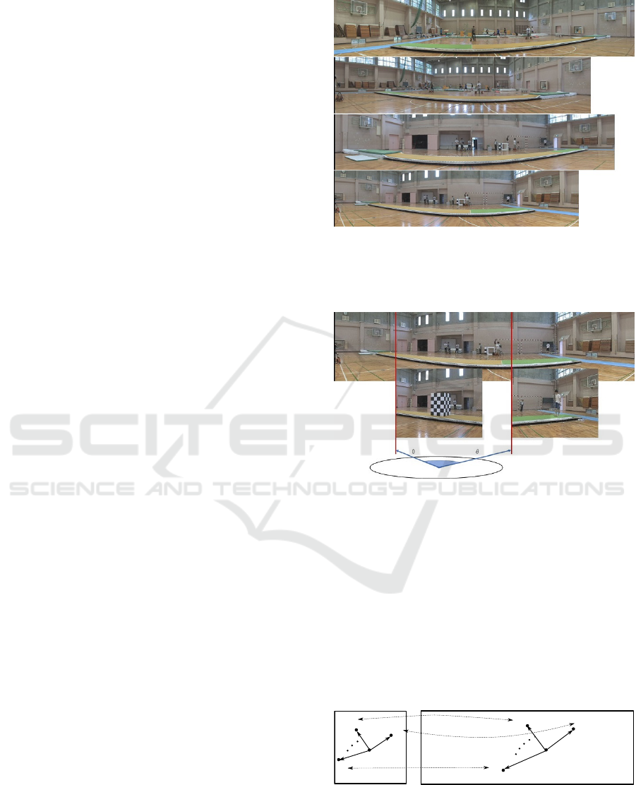
The panoramic images unfoldedfrom the cylindri-
cal surface are shown in the Fig.4. When the camera
at the reference pose was calibrated in the subsection
3.4, the vertical and horizontal angles of view of the
camera are obtained, and the rotation angle per one
pixel is also derived. The horizontal and vertical axes
of the panoramic image can be described as the pan
and tilt rotation angles, respectively.
4 CALIBRATION IN PAN-ZOOM
The subsection 3.4 described camera calibration at the
reference position. This section will describe the cal-
ibration of the camera in pan-zoom.
Figure 4: Panorama images from cameras 1, 2, 3 and 4 in
order from the top.
4.1 Matching with Panoramic Images
Figure 5: Two positions on the panoramic image from cam-
era 1, that match with the camera calibration image taken
at the reference pose and the image taken after panning, re-
spectively.
The camera calibration image taken in the reference
position is collated with the panoramic background
image. The matched position becomes an origin on
the panoramic image. Fig.5 shows the panoramic im-
age of camera 4 selected from the Fig.4, on which
the origin is denoted by matching with the calibration
image. We also obtain the matched position of the
image shot by panning and zooming camera with the
panoramic image as shown in Fig.5.
panorama image
target image
a
2
a
i
a1
b
2
b
i
x
b1
a
0
Figure 6: The left figure denotes a cylindrical image trans-
formed from the perspective image. The right figure de-
notes the panoramic image of the background.
GRAPP 2022 - 17th International Conference on Computer Graphics Theory and Applications
166
When the feature point correspondences between
the target image and the panoramic image and the ori-
gin of the target image are given, the problem is to
obtain the corresponding destination of the origin on
the panoramic image, and zoom ratio. Fig.6 shows
corresponding pair, a
i
= (r
i
,s
i
)
T
and b
i
= (p
i
,q
i
)
T
,
the origin of the target image, a
0
= (r
0
,s
0
)
T
, and the
corresponding destination, x = (p
0
,q
0
)
T
.
4.2 Pan /Zoom Camera Calibration
According to eq.(6), the transformation from a per-
spective image to a cylindrical image is
r = k
u
tan
−1
u−u
0
k
u
f
+ r
0
s = k
u
v−v
0
p
(u−u
0
)
2
+ k
2
u
f
2
+ s
0
(6)
When the focal length f is changed to η times
by zooming, the relative position (u −u
0
,v −v
0
)
T
of the projection point (u,v)
T
for the image center
point (u
0
,v
0
)
T
also changes to η(u
f
−u
0
,v
f
−v
0
)
T
as shown in the Fig.7. Here, (u
f
,v
f
)
T
is the pro-
jection point before zooming. Even if f and (u −
u
0
,v −v
0
)
T
in the eq.(6) are replaced with to η f and
η(u
f
−u
0
,v
f
−v
0
)
T
, the projection position on the
cylindrical surface does not change since the zoom
ratio η is canceled by the numerator and denomina-
tor. This is natural because the focal length of the
perspective transformation has nothing to do with the
cylindrical transformation.
f
f
0 0
0 0
Opt. axis
Line of sight
Projection center
O
Figure 7: Change of the relative position on the perspective
image after zoom up.
However, when a perspective image taken by
zooming and panning is transformed into a cylindrical
image by the eq.(6), the effect of zooming appears on
the cylindrical image. This is because the focal length
is not multiplied by the zoom ratio η. On the contrary,
the zoom ratio can be obtained from this effect.
The transformation to cylindrical coordinates be-
fore zooming is given by the eq.(6), which is repre-
sented by the feature points on the panoramic image.
p− p
0
= k
u
tan
−1
u
f
−u
0
k
u
f
q−q
0
= k
u
v
f
−v
0
p
(u
f
−u
0
)
2
+ k
2
u
f
2
(7)
On the other hand, since the points affected by
the ratio η by zooming are represented by the feature
points on the cylindrical image, we have
r−r
0
= k
u
tan
−1
u−u
0
k
u
f
s−s
0
= k
u
v−v
0
p
(u−u
0
)
2
+ k
2
u
f
2
(8)
Assuming that the image center (u
0
,v
0
) and the scale
k
u
does not change before and after zooming, we have
the projection position as seeing the Fig.7.
u−u
0
= η(u
f
−u
0
)
v−v
0
= η(v
f
−v
0
)
(9)
The position after zooming can be observed, but the
position before zooming cannot be observed. Setting
ν with 1/η,
u
f
−u
0
= ν(u−u
0
)
v
f
−v
0
= ν(v−v
0
)
(10)
Substitute this relationship into the eq.(7) and com-
pare the ratios of the left and right sides of the eqs.
(7) and (8), we have
p− p
0
r−r
0
=
tan
−1
ν(u−u
0
)
k
u
f
tan
−1
u−u
0
k
u
f
q−q
0
s−s
0
= ν
s
ν
2
(u−u
0
)
2
+ k
2
u
f
2
(u−u
0
)
2
+ k
2
u
f
2
(11)
This equation is a non-linear equation with (p
0
,q
0
)
and ν as unknowns.
Let’s linearize this nonlinear equation. Using the
approximate equation tan
−1
θ
∼
=
θ (suppose |θ| to be
small), the first equation of the eq.(11) is
p− p
0
r−r
0
= ν (12)
Since ν is near 1, let’s set ν = 1 + δ, and expand
the right side
√
∗ of the second equation of eq.(11)
with δ into the Taylor series. Ignoring the second and
higher order small terms, we have
s
(1+ δ)
2
(u−u
0
)
2
+ k
2
u
f
2
(u−u
0
)
2
+ k
2
u
f
2
∼
=
1+
(u−u
0
)
2
(u−u
0
)
2
+ k
2
u
f
2
δ
(13)
Pan-zoom Motion Capture in Wide Scenes using Panoramic Background
167
Furthermore, supposing (u −u
0
)
2
≪ k
2
u
f
2
, since the
second term on the right side is a higher-order small
term, we can ignore it. we have
q−q
0
s−s
0
= ν (14)
These approximations hold near the center of the im-
age, where the cylindrical image almost equals the
perspective image.
Arranging the eqs.(12) and (14) as a system of lin-
ear equations,
r−r
0
1 0
s−s
0
0 1
ν
p
0
q
0
=
p
q
(15)
By solving the aboveequations constructed from mul-
tiple corresponding points, the zoom ratio η = 1/ν
and the position (p
0
,q
0
)
T
on the panoramic image can
be obtained. With this solution as the initial solution,
an exact solution can be obtained by solving the non-
linear eqs.(11), but in this paper, the initial solution
is used as the final solution. Of the matched position
(p
0
,q
0
)
T
, q
0
is affected by tilt rotation while p
0
is
affected by pan rotation. Tilt pose can also be cali-
brated, but in our experiment, the tilt rotation was not
performed due to the limit of manual operation of the
camera.
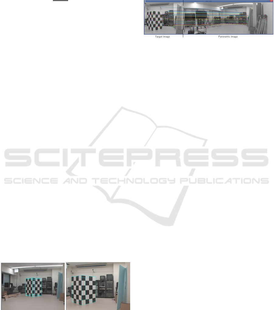
4.3 Experiments of Pan-zoom Camera
Calibration
Let’s show the calibration of pan-zoom cameras in the
experimental laboratory scene. At an initial step, a
calibration object is shot in the center of image, and
check where the calibration object positions. The ref-
erence pose of the camera is obtained from the im-
age of this calibration object. When the model of the
calibrated object is projected using the obtained cam-
era parameters, one can see that the blue line wire-
frame model matches the object, as shown on the left
in Fig.8.
Figure 8: Left: Calibration result at reference pose, Right:
Calibration result after pan / zoom.
A panoramic image of the background is created
from the movie obtained by pan-rotating the cam-
era after removing out the calibration object from the
scene. Next, return the calibration object to its origi-
nal position, then pan the camera to the right to zoom
in and shoot the calibration object. The shot target
image is shown in the right of Fig.8.
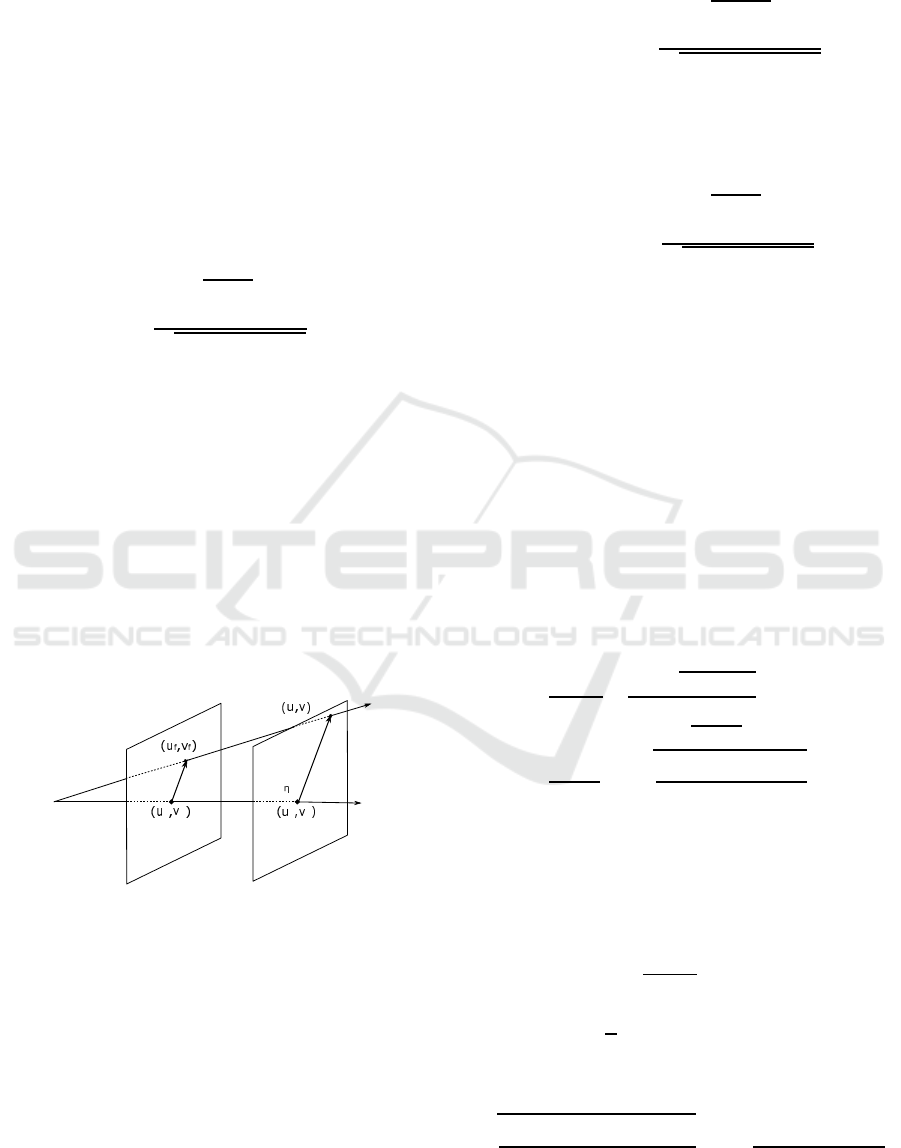
Figure 9: The left end is the image of the target taken af-
ter pan-zooming the camera. The right part is a panoramic
image of the background. The result of matching both by
AKAZE (Alcantarilla et al., 2013) is shown by straight lines
connecting the corresponding feature points.
The target image is collated with the panoramic
image. The matching result is shown in Fig.9.
AKAZE (Alcantarilla et al., 2013) extracts feature
points which are indicated by small circles. Of these
feature points, matched pairs are associated with line
segments. We can obtain the focal length f from the
zoom ratio η calculated from the associated pairs, and
the pan rotation angle from the position (p
0
,q
0
) on
the panoramic image, and update the camera parame-
ters.
Strictly speaking, when zooming, the lens system
moves back and forth, so the projection center may
move and a parallax appears. Moreover, we do not
consider a distortion of the camera lens. We were
worried that these effects would reduce the accuracy
of camera calibration. Using the updated camera pa-
rameters, overlay a model of the calibrated object on
the target image. Fig.8 right denotes the blue line
wireframe model drawn on the calibration object, in-
dicating that the camera is calibrated almost correctly.
5 TRACKING
After obtaining the camera parameters, the next is-
sue is to estimate the body pose in motion. Frame by
frame pose estimation means tracking the body. The
tracking is performed by matching an articulated body
model with each body image of the sequence. We per-
formed the tracking based on the existing differential
approach (Yamamoto et al., 2014; Kobayashi et al.,
2018), where the body model has to be manually
matched with the body image at several keyframes in-
cluding the start and end frames to eliminate a track-
ing drift (Yamamoto, 2005). Tracking experiments
can be seen in videos of (Kobayashi and Yamamoto,
2015; Kobayashi and Yamamoto, 2018).
GRAPP 2022 - 17th International Conference on Computer Graphics Theory and Applications
168

6 EXPERIMENTS
Experiments show the effects of camera panning and
zooming, which are the two advantages of the method
proposed in this paper.
6.1 Panning Effects
Let’s show panning effects by capturing motion of a
gymnastic athlete in floor exercise. After shooting
the exercise, motion capture is performed by offline.
Captured results are overlapped on the panoramic im-
age from camera 3 as shown in the upper row of
Fig.10, where results sampled from 171 frames in to-
tal are represented by the skeleton model. The red-
only skeleton represents the pose given in keyframes,
and the color-coded skeleton for each part represents
the pose calculated by tracking in between keyframes.
The horizontal axis of the panoramic image denotes
pan rotation angle. The middle row of Fig.10 de-
notes the corresponding tracking images in movie
from camera 3. The red arrow indicates position
matching each target image with the panoramic im-
age. The camera 3 is panning from right to left. The
lower row in Fig.10 shows the corresponding CG im-
age of the athlete reconstructed from a camera view
different from any four cameras.
6.2 Zooming Effects
A pedestrian is captured with pan-zoom cameras. At
this time, if the pedestrian moves away, the focal
length is lengthened to zoom in, and if it gets too
close, the focal length is shortened to zoom out, and
the entire body is always adjusted so that it fits within
the image frame. This pan / zoom operation was per-
formed manually.
The top views of the movement of the camera and
the path of the pedestrian are shown in Fig.11 which
shows 4 frames out of 150 tracking frames in total.
The focal length is shown in the Fig.12. In this figure,
the referencefocal length when the camera calibration
object was shot is also drawn with a dotted line. The
calibration object was placed near the center of the
rectangle with the camera position as the apex.
The pedestrian starts from the vicinity of the cam-
era 3 and its path draws an arc to approach the camera
2. Initially, the camera 3 sets the focal length shorter
than the reference focal length in order to capture a
nearby pedestrian, but increases the focal length as
the pedestrian moves away. On the other hand, in the
camera 2, the focal length is shortened because the
pedestrian gradually approaches. For cameras 1 and
4, the focal length is always longer than the reference
focal length because the pedestrian is farther than the
position where the calibration object was placed.
The Fig.13 shows the images taken with the vary-
ing focal length and the images taken with the fixed
focal length for cameras 3 and 4. For each camera,
the upper row is the images at the time of variable
focus, and the lower row is the images at the time
of fixed focus. The shooting time is the first, 50th,
100th, and 148th frames from the left. The captured
skeleton overlaps on the body image. The fixed focus
image in the lower row is estimated from the vari-
able focus image on the upper row. When the vari-
able focal length is f, the projected position (x, y)
T
of
the position (X,Y, Z)
T
in space is given by the eq.(1).
Supposing the fixed focal length to be f
0
which is the
reference focal length, the projection position (x
′
,y
′
)
is given by
x
′
= f
0
X
Z
y
′
= f
0
Y
Z
(16)
From the eqs.(1) and (16), the correspondence from
the variable focus image to the fixed focus image is
x
′
=
f
0
f
x
y
′
=
f
0
f
y
(17)
The fixed focus image is made by this transformation
from the variable focus image.
According to Fig.12, since the ratios f
0
/ f of the
cameras 1 and 4 are always less than 1, the variable
focus image is reduced to make a fixed focus image.
Even objects that look small in the fixed focus image
can be enlarged and easily measured by making the
focal length variable like in camera 4 of Fig.13. On
the other hand, with cameras 2 and 3, the ratio f
0
/ f is
sometimes larger than 1, so the fixed-focus image ex-
tends beyond the angle of view of the camera. In fact,
in the fixed-focus images of the 1st and 50th frames
of the camera 3, the toes of the pedestrian are hidden
outside of the view. By adjusting the focal length, the
body image can be kept within the field of view.
7 CONCLUSION
This paper proposed a motion capture system by pan-
zoom cameras. The camera calibration is performed
by matching the panoramic image of the background
taken in advance with the background of the body im-
age. Using the calibrated multi-view camera system,
it is possible to capture an athlete’s floor exercise in
the wide gymnasium.
Pan-zoom Motion Capture in Wide Scenes using Panoramic Background
169
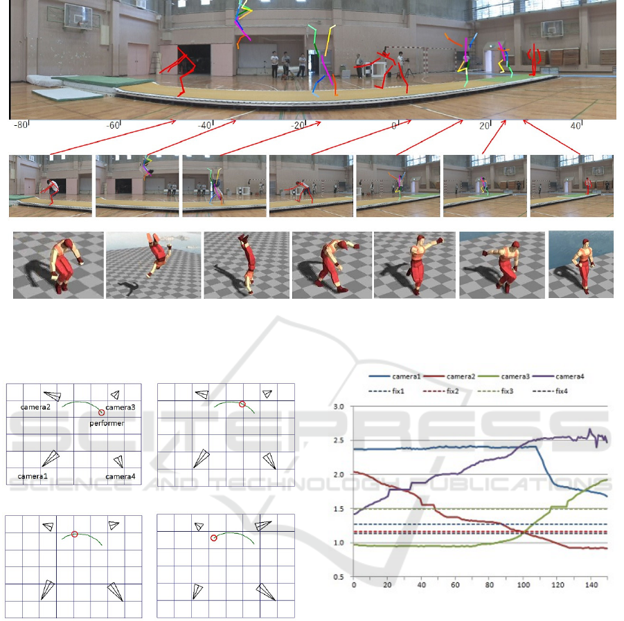
Figure 10: Upper row: The sampled results of motion capture are overlapped on the panoramic images as a stick model.
Middle row: Arrange sampled tracking results which match the panoramic image at position indicated by red arrow. Lower
row: Corresponding CG images of the athlete reconstructed from different camera view.
frame 1 frame 50
frame 100 frame 148
Figure 11: The path of the pedestrian and the pan and zoom
of the camera in tracking on a grid with 2m per one unit.
The camera is represented by an isosceles triangle of which
apex and height denote a viewpoint and focal length, re-
spectively. The pedestrian draws a green arc on which a red
circle denotes a current position.
In the future, we plan to develop a more precise
calibration method that takes into account lens distor-
tion and a motion parallax when zooming, and com-
pare it with other methods (Shum and Szeliski, 2000;
Sinha and Pollefeys, 2006; Wu and Radke, 2013) such
as self-calibration.
Figure 12: The focal length of each camera. A dot line de-
notes the focal length by camera calibration at the reference
pose. The horizontal axis denotes the time by frame num-
ber. The vertical axis denotes the focal length by × 640
pixels.
ACKNOWLEDGEMENTS
I would like to thank Mr. Daisuke Kobayashi, Mr.
Takashi Igarashi and Mr. Shinya Suzuki for their
contributions for the early works, and also thank Mr.
Shotaro Kawaguchi for his gymnastic performance.
This work was supported by JSPS KAKENHI Grant
Numbers 18K11602, 26330190 and 21500161.
GRAPP 2022 - 17th International Conference on Computer Graphics Theory and Applications
170
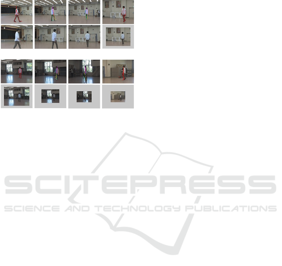
frame 1 frame 50 frame 100 frame 148
camera 3
camera 4
Figure 13: Images taken with the variable focal length and
images taken with the focal length fixed at the reference fo-
cal length are shown for each camera. The upper row is
the images for the variable focal length, where the skele-
ton of the body is superimposed on the image as a motion
capturing result. The lower row is the images for the fixed
focal length where the fixed focus image is made from the
variable focus image. The 1st, 2nd, 3rd and 4th columns
correspond to the 1st, 50th, 100th, and 148th frames, re-
spectively.
REFERENCES
Alcantarilla, P. F., Bartoli, A., and Davison, A. J. (2012).
Kaze features. In ECCV, volume 31, pages 214–227.
Alcantarilla, P. F., Nuevo, J., and Bartoli, A. (2013). Fast
explicit diffusion for accelerated features in nonlinear
scale shapes. In British Machine Vision Conference,
pages 117–126.
Bay, H., Ess, A., Tuytelaars, T., and Gool, L. V. (2008).
Speeded-up robust features (surf). Computer Vision
and Image Understanding, 110(3):346–359.
Cannelle, B., Paparoditis, N., and Tournaire, O. (2010).
Panorama-based camera calibration. In IAPRS, vol-
ume XXXVIII, Part 3, pages 73—78.
Joo, H., Liu, H., Tan, L., Gui, L., Nabbe, B., Matthews,
I., Kanade, T., Nobuhara, S., and Sheikh, Y. (2015).
Panoptic studio: A massively multiview system for
social motion capture. In ICCV.
Kobayashi, D., Igarashi, T., and Yamamoto, M. (2018).
Motion capture from multi-view mobile cameras. In
CVIM (Japanese Edition), volume 2018-CVIM-210,
pages 1–6.
Kobayashi, D. and Yamamoto, M. (2015). Wide-range mo-
tion capture from panning multi-view cameras. In
ACM SIGGRAPH Asia 2015 Posters, page Article 36.
Kobayashi, D. and Yamamoto, M. (2018). Capturing
floor exercise from multiple panning-zooming cam-
era. In Eurographics / ACM SIGGRAPH Symposium
on Computer Animation-Posters.
Kurihara, K., Hoshino, S., Yamane, K., and Nakamura,
Y. (2002). Optical motion capture system with pan-
tilt camera tracking and realtime data processing. In
International Conference on Robotics & Automation,
pages 1241–1248.
Lowe, D. G. (2004). Distinctive image features from scale-
invariant keypoints. International Journal of Com-
puter Vision, 60:91–110.
Nageli, T., Oberholzer, S., Pl¨uss, S., Alonso-Mora, J., and
Hilliges, O. (2018). Flycon: real-time environment-
independent multi-view human pose estimation with
aerial vehicles. volume 37, page Article 182.
Rhodin, H., Richardt, C., Casas, D., Insafutdinov, E.,
Shafiei, M., Seidel, H., Schiele, B., and Theobalt, C.
(2016). Egocap: Egocentric marker-less motion cap-
ture with two fisheye cameras. ACM Trans. Graph.,
35(6):Article 162.
Saini, N., Price, E., Tallamraju, R., and Black, M. J. (2019).
Markerless outdoor human motion capture using mul-
tiple autonomous micro aerial vehicles. In ICCV.
Shum, H.-Y. and Szeliski, R. (2000). Systems and exper-
iment paper: Construction of panoramic image mo-
saics with global and local alignment. International
Journal of Computer Vision, 36(2):101–130.
Sinha, S. N. and Pollefeys, M. (2006). Pan?tilt?zoom
camera calibration and high-resolution mosaic gen-
eration. Computer Vision and Image Understanding,
103(3):170–183.
Sundaresan, A. and Chellappa, R. (2005). Markerless mo-
tion capture using multiple cameras. In Computer Vi-
sion for Interactive and Intelligent Environment.
Tsai, R. Y. (1986). An efficient and accurate camera cal-
ibration technique for 3d machine vision. In CVPR,
pages 364–374.
Ukita, N. and Matsuyama, T. (2005). Real-time cooperative
multi-target tracking by communicating active vision
agents. Computer Vision and Image Understanding,
97(2):137–179.
Wu, Z. and Radke, R. J. (2013). Keeping a pan-tilt-zoom
camera calibrated. IEEE Transactions on Pattern
Analysis and Machine Intelligence, 35(8):1994–2007.
Xu, L., Liu, Y., Cheng, W., Guo, K., Zhou, G., Dai, Q.,
and Fang, L. (2016). Flycap: Markerless motion cap-
ture using multiple autonomous flying cameras. IEEE
Transactions on Visualization and Computer Graph-
ics, 24(8):2284–2297.
Yamamoto, M. (2005). A simple and robust approach to
drift reduction in motion estimation of human body.
The IEICE Transactions on Information and Sys-
tems(Japanese Edition)D-II, J88-D-II(7):1153–1165.
Yamamoto, M., Isono, S., , and Wada, Y. (2014). Determin-
ing pose of intertwisting human bodies from multiple
camera views. The journal of the Institute of Image
Information and Television Engineers(Japanese Edi-
tion), 68(8):J358–J370.
Pan-zoom Motion Capture in Wide Scenes using Panoramic Background
171
