
Assisting Storyboarders in Expressive 3D Pose Creation with a 2D
Sketch-based Interface
Sophia Mouajjah
1,2
and Cedric Plessiet
1
1
INREV, Paris 8 University, Saint-Denis, France
2
Superprod Studio, Paris, France
Keywords:
Gestural Interface, Storyboarding, Character Posing, Co-creative Process, Storytelling, Layout, Feedback
Loop, Sketch-based Interface.
Abstract:
Storyboarding is an ideation and prototyping process that constitutes one of the keystones in visual and nar-
rative productions, such as filmmaking and performing arts. During this step, storyboard artists start giving
poses and expressions to their characters. However, in the case of 3D film making, the final movie will be
transposed from a 2D to a 3D medium, which means that artists do not have an accurate view of the result
of their work. Existing 3D interfaces do not suit the storyboarders’ needs, as their complexity tend to impede
and alter their creative process. This study focus on the development of an intuitive system that allows artists
to pose 3D characters using simple 2D strokes as an interaction method. Our technique combines several
representation modes to let users incrementally develop their poses in a monocular view. We evaluated the
system by posing various characters with different anatomies and levels of details, which showed that it has
the advantage of being flexible and helps in gaining time compared to the classical keyframe method.
1 INTRODUCTION
As a powerful narrative tool, the storyboard depicts
the story’s actions, rhythm and emotions by offer-
ing the first visual aspect of the movie. One of the
main tasks entrusted to storyboarders is the character
staging, acting and the creation of expressions. The
majority of existing storyboard tools provide a 2D
sketching interface, as it allows artists to freely and
intuitively experiment aesthetic and narrative options
by creating expressive visuals. However, these tools
thoroughly ignore the 3D nature of the final work. As
a consequence, a gap appears between the 2D and 3D
media, which generates inaccuracies during the tran-
sition between these steps. Not being able to see any
3D feedback prevents the director from checking if
the narrative and visual ideas put in the storyboard
panels will effectively work when transposed into a
3D environment.
If sketching tools are intuitive, 3D techniques re-
main complex and laborious, especially for non ex-
pert users. In the case of keyframe animation, the
user must manipulate 3D controllers and several pa-
rameters, which is quite unnatural. These constraints
would burden and slacken traditional artists and neg-
atively interfere with their creative process.
The main goal of this study is to facilitate the tran-
sition between preproduction and production in the
case of character posing. To do so, we developed
a 3D posing method that exclusively relies on 2D
sketch gestures. Users are inserted into a feedback
loop where they can operate with three representation
modes to build a 3D pose. This system offers an in-
tuitive interface that allows artists to quickly pose 3D
characters in a fixed 2D panel, respecting the main
constraints of the storyboarders. We begin this paper
by exploring the representation methods established
by previous research on the subject. Then, we define
the challenges that are specific to the field of story-
boarding and we describe the implementation of our
method. Finally, we analyze the results and describe
the improvements to be made in our future works.
2 BACKGROUND
2.1 Abstractions
Poses can be depicted by artists using several repre-
sentation methods that we will call abstractions here,
as you can see in figure 1.
126
Mouajjah, S. and Plessiet, C.
Assisting Storyboarders in Expressive 3D Pose Creation with a 2D Sketch-based Interface.
DOI: 10.5220/0010782000003124
In Proceedings of the 17th International Joint Conference on Computer Vision, Imaging and Computer Graphics Theory and Applications (VISIGRAPP 2022) - Volume 2: HUCAPP, pages
126-133
ISBN: 978-989-758-555-5; ISSN: 2184-4321
Copyright
c
2022 by SCITEPRESS – Science and Technology Publications, Lda. All rights reserved

Figure 1: Examples of abstractions that can be interpreted
by sketch posing methods.
2.1.1 Stick Figure
The vast majority of the sketch posing interfaces re-
quire stick figures as input. Some of them add an
automatic size correction feature, like in (Lin et al.,
2012)’s research. In other methods, stick figures can
be sketched in a totally free-form way, like in (Choi
et al., 2012) and (Mao et al., 2006)’s works. Stick
figures have the advantages of being close to the real
structure of the 3D skeleton, which makes them easier
to parse and to interpret foreshortening effects. The
main drawbacks when using stick figures are that they
imply symmetry ambiguities and don’t provide any
volume hint, nor twist information.
2.1.2 Line of Action
(Guay, 2015) uses abstraction concepts inspired by
traditional artists and animators, such as the line of
action, which is a simple unique curve that indicates
the global stream and dynamic of the pose. Other
systems have integrated this concept to posing oper-
ations such as (Mahmudi et al., 2016), (Low, 2014)
and (
¨
Oztireli et al., 2013). The line of action abstrac-
tion is intuitive, expressive and quick to produce as
it doesn’t involve the process of fully sketching the
character. That makes it particularly suited for incre-
mental processes. However, depth, volume and twist
information can be difficult to interpret directly.
2.1.3 Silhouette
Outline or silhouette representations have the benefit
of helping in the definition of global shapes and de-
termining the area an element should take on screen.
But they tend to be less intuitive to draw for artists
and hard to parse, as they don’t clearly depict the dif-
ferent body elements and produce symmetry ambigu-
ities. This kind of representation is more suited for
procedurally driven parts such as hair, as we can see
in (Seki and Igarashi, 2017)’s study.
2.1.4 Gesture Drawing
(Bessmeltsev et al., 2016) developed an interface that
uses gesture drawings as input, which are intuitive and
suggestive sketches representing a pose in the least
ambiguous way. Gesture drawings are less technical
than stick figures, more natural than outlines and less
abstract and ambiguous than lines of action. How-
ever, unlike these simple abstractions, they need a
complex calculation step to parse the input sketches,
which make it difficult to use in real time.
2.1.5 Shape Decomposition
Characters can also be constructed by dividing their
parts into several shapes, such as squares or spheres,
like in (Thorne and Burke, 2004)’s system. (Hahn
et al., 2015) also uses decomposed outlines to rep-
resent body parts.
2.2 Data Requirements
Sketch posing methods can rely on existing motion
databases, like in (Jain et al., 2009) or (Lin, 2006)
technique. Other research also exploit comparisons
between drawings from users and rendered poses
from databases, such as (Lv et al., 2015) and (Wei
and Chai, 2011). Sketches can be used as queries to
retrieve poses in a large database, like (Choi et al.,
2012) and (Xiao et al., 2015) research. More recently,
learning algorithms have been developed to recognize
or reconstruct 3D poses from sketches using datasets,
like in (Akman et al., 2020). We can also note tech-
niques that require user annotations to specify joints
positions, such as in (Gouvatsos, 2018) .
3 CHALLENGES
Storyboard drawings hold specificities that must be
taken into account when building sketch posing sys-
tems, as they are usually rough and simplified.
Firstly, our tool should minimize the most tedious
and least artistic tasks to let the user focus more on
an aesthetic and narrative works. Therefore, it has to
be fully automated: we do not want to impose any
labeling step to the user.
Storyboard poses tend to be expressive: artists
use exaggerations and emphasis, such as stretch and
squash deformations, to enhance an emotion, which
may create flawed proportions. It should be taken into
account when analyzing sketches.
Our storyboarding system must handle depth am-
biguities, in the most plausible way: given a 2D pro-
jection, several 3D solutions could correspond to the
same 2D representation.
Moreover, we want to integrate the artist into a
retroactive feedback loop with the digital tool. Thus,
Assisting Storyboarders in Expressive 3D Pose Creation with a 2D Sketch-based Interface
127
the algorithms must be fast enough to offer a 3D feed-
back in real time. To let the user refine his work pro-
gressively, the workflow has to remain incremental.
In addition, we don’t want to confuse, disturb
or slow down the storyboarder while conceiving the
panels. Sketching should be the unique interaction
mode. No 3D operations should be needed to pose
the character. As a consequence, the system has to
stay monocular: artists should be able to create the
pose exclusively into their frame view.
Finally, we want the tool to be usable by any kind
of animation production team and for any type of
project. As a consequence, the algorithm should not
be based on any pose or motion database, which tends
to be limited to realistic bipedal characters.
4 OVERVIEW
In our sketch posing method, we provide a combina-
tion of sketching tools the storyboarder can employ
according to his needs. The majority of the interac-
tions with the system are done by sketching. During
the session, the artist is always included in a retroac-
tive feedback loop, as all of his actions are imme-
diately applied to the 3D scene and displayed in the
viewport. The user interface is visible in figure 3-A.
5 IMPLEMENTATION
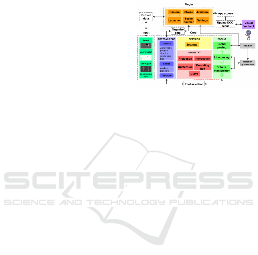
5.1 Architecture
Our sketch posing tool is divided in two sections, as
you can see in figure 2. The first one is the core sys-
tem: it contains several modules that are necessary for
the pose computation. The abstraction modules define
useful objects that will be exploited during the pose
estimation stage, such as the camera, the stroke and
the 3D object armature. The posing modules hold the
three posing tools: global posing, line posing and the
sphere manipulator, their algorithms will be described
in 5.3, 5.4 and 5.5. These tools need the user settings
and geometry modules to perform calculations. The
output data of the core system depends on the posing
tool selected, it can be positions or rotations to up-
date in the scene, with a reference to the labels of the
armature elements to edit.
5.2 Scene Data Management
The first step in our sketch posing system consists in
gathering all the required data from the storyboard
Figure 2: Sketch posing system architecture and modules.
scene and organize them in order to ease the pose cal-
culation. The plugin part of our system extracts re-
quired data from a digital content creation tool, and
the core part structures it to handle pose estimation.
Our system assumes the 3D camera has already
been placed in the 3D scene. Thus, the framework
takes several camera parameters as input, such as the
normalized world transformation matrix and the di-
rection vector.
The second data type we must handle is the 2D
sketch stroke. A stroke is a curve formed by a set
of ordered points, usually created with a graphic pen
tablet. In our system, strokes are drawn on a 2D plane
that is parallel to the camera clipping planes. We ex-
tract the position of each stroke point in the world
space coordinate system, as well as the pen pressure
values.
Regarding the character skeleton, we made the
choice to take joints positions and bones labels as in-
put rig data to our system. Bones are segments that
connect a first joint (head joint) to a terminal joint
(tail joint). They can be rotated by taking the tail joint
as the center of rotation. Joints are the smallest rig
elements and represent the point at which bones are
connected.
5.3 Line Posing
The line posing tool allows artists to set up a character
pose by sketching strokes onto a 3D rigged object. In
our system, the bone length remains constant and the
first joint of the chain is never moved. Line posing
operations consist in selecting the right bone chain to
edit, analyze the curve to identify its type and parse
it to extract landmark points. Then, the tool replaces
the joints in 3D space and computes new bone rota-
tions. The plugin picks this data and applies it to the
armature in the 3D viewport. The following sections
describe the process of line posing.
HUCAPP 2022 - 6th International Conference on Human Computer Interaction Theory and Applications
128

5.3.1 Body Part Selection
The first step of our line posing process consists in
identifying the body part to edit. For now, we decided
to define the editable chain according to its proximity
to the user stroke. To do so, we transpose the stroke
points and each chain’s first joint to screen coordi-
nates. Then, we select the chain for which its top
joint is the closest to the first stroke point. Finally,
the stroke is translated to make its first point lie onto
the chain’s first joint in the camera view.
5.3.2 Stroke Type Analysis
The tool must be able to handle various stroke styles.
According to his needs, the user can trace stiff an-
gular lines, which can be similar to the kind of lines
we find in stick figures. These curves usually have
several marked turning points, which are clues that
can be used to identify joint positions. The second
type of shape handled by our line posing tool gath-
ers smoother and more supple lines that do not have
marked turning points. They are generally used by
artists to indicate slighter and more subtle intentions
in body pose.
Both types of line are represented in figure 3-B
and must be parsed differently to make the posing
system more accurate. However, we think the user
shouldn’t have to manually activate parameters in the
interface to indicate the kind of stroke he intends to
draw. As a consequence, we first analyze the input
curve to automatically identify the curve type we will
have to process.
To do so, we use the sinuosity index theorized by
(Mueller, ). We compare the result with an arbitrary
threshold value ε as illustrated in the inequation 1.
n−1
∑
i=0
k
−−−→
S
i
S
i+1
k
k
−−→
S
0
S
n
k
> 1 −ε (1)
If the ratio is superior to the threshold value, the
stroke will be parsed as an angular stroke. By default,
we set the threshold value as 0.05.
5.3.3 Joint Landmark Detection and
Replacement
Parsing Angular Lines and Replacing Joints. The
system starts by looking for landmarks, which are
points on the 2D stroke that match with the chain
joints. Those points are extracted using a variant
of the Ramer Douglas Peucker algorithm (Douglas
and Peucker, 1973) that takes the number of required
points as input, which corresponds here to the number
of joints.
Once the landmark points have been extracted, we
must inversely project them in the 3D world space and
determine each joint’s new position. For all of the
landmark points, we compute their depth order (see
5.3.4). Then, for each bone in the chain, we build a
sphere with the bone head joint in worldspace coordi-
nates J
ws
j
as center and the bone length Bl
j
as radius.
We also build the segment from the camera position
C
ws
pos
to the tail joint’s matching landmark point on the
stroke L
ws
j+1
. Next, we compute the intersection point
I
ws
j+1
between the line and the sphere to get the current
bone’s tail joint J
ws
j+1
new position in world space. If
several points have been found, we use the depth mask
computed previously to select the nearest or farthest
point from the camera. A representation of this pro-
cess can be viewed in figure 3-C for the first iteration.
Figure 3: User interface screenshot (A). Line types (B). An-
gular line joint repositioning process and bone angle com-
putation at iteration 0 (C). Bone rotation computation when
parallel to the camera clipping plane (D).
If no intersection point could be found, which
means that the segment between the landmarks is
longer than the bone, we consider that the bone is
parallel to the camera clipping plane. In that case,
the system looks for the projection of the tail joint’s
matching landmark point Lpro j
ws
j+1
from the camera
position on the plane that is normal to the camera di-
rection
−−→
C
ws
dir
and passing by the current head joint J
ws
j
.
Then, we search for the point on the line J
ws
j
Lpro j
ws
j+1
that is at the Bl
j
distance from the head joint. The tail
joint position J
ws
j+1
is updated with this new position,
as described in figure 3-D. To handle cases where the
represented bone segment is too long, two modes are
available: by default, the system sticks to the land-
mark positions. Otherwise, if we want the next joints
in the chain to be adjusted to preserve the global shape
of the stroke, we compute the difference from the
original landmark position L
ss
j+1
to the new tail joint
position J
ss
j+1
in screen space coordinates. Then, we
update the following landmarks in the list L
ss
by sub-
tracting their position with the computed difference,
and we set their new world space position L
ws
accord-
ingly. We continue the iterations until the last joint of
the chain has been replaced.
Assisting Storyboarders in Expressive 3D Pose Creation with a 2D Sketch-based Interface
129

Parsing Smooth Lines and Replacing Joints. The
first step, described in figure 4, consists in finding the
new position of the last chain joint J
ws
m
in worldspace
coordinates according to the last stroke point S
n
. We
compute the intersection point I
ws
m
between the line
from the camera position C
ws
pos
to the last stroke point
S
ws
n
with the sphere that has the first chain joint J
ws
0
as center and the chain total cumulative bone length
Cl as radius. If an intersection point is detected, we
replace the last joint position with it.
Figure 4: Calculation and replacement of the last joint of
the chain if the bone is foreshortened.
Else, we consider that the chain is parallel to the
camera clipping plane. The stroke points are pro-
jected on the plane P
ws
0
that is normal to the camera
direction and passing by the first joint J
ws
0
. We have
to find the intersection point between the bone chain
and the projected stroke Spro j
ws
by maximizing its
length. To do so, for each projected stroke segment
Spro j
ws
i
Spro j
ws
i+1
, we compute the intersection point
between the current segment and the circle that has
the first joint J
ws
0
as center and the chain length Cl as
radius, lying on P
ws
0
. We update the position of the
last joint J
ws
m
to the first intersection point found (fig-
ure 5-A).
Figure 5: Replacement of the last joint of the chain if it is
parallel to the camera clipping plane (A). Replacement of
the bone chain to match the stroke shape at iteration 0 (B).
Then, each intermediate joint J
ws
j
in the chain is
replaced on the line from the first to the last joint
J
ws
0
J
ws
m
with respect to each original bone length Bl
j
.
Lastly, we determine the final position of the in-
termediate joints to make them consistent with the in-
put curve (figure 5-B). For each bone in the chain,
the system computes a projection point J pro j
ws
j
of
the bone head joint J
ws
j
on the plane P
ws
j
that is nor-
mal to the camera direction and passing by the bone
tail joint J
ws
j+1
. Thereafter, for each stroke segment
S
ws
i
, we project its terminals onto P
ws
j
. We look for
an intersection point between the projected segment
Spro j
ws
i
Spro j
ws
i+1
and the circle Circle
ws
j
constructed
using the projected joint J pro j
ws
j
as center and the
distance J pro j
ws
j
J
ws
j+1
from the projected head joint to
the tail joint as radius. For each potential intersection
point I
ws
k
, we compute the ratio r
j
between the dis-
tance Spro j
ws
i
I
ws
k
from the stroke segment’s first point
to this point and the distance Spro j
ws
i
Spro j
ws
i+1
from
the stroke segment’s first point to its last point. If sev-
eral intersection points have been found, we take the
point that is associated with the highest ratio r
max
. Fi-
nally, we assign this point position value to the current
tail joint J
ws
j+1
position.
5.3.4 Depth Order
As described in the background section 2, by us-
ing the bone’s real length and the parsed stroke seg-
ment’s length, we can compute the joints’ depth val-
ues. However, if the bone is not normal or parallel
to the camera plane, two solution points are available
for the tail joint: the bone can point towards the cam-
era or in the opposite direction. To resolve this am-
biguity, we decided to establish the depth specifica-
tion in the artist’s workflow. As it has already been
done in (Thorne and Burke, 2004)’s work, we took
inspiration from traditional artists who tend to rep-
resent closer elements with thicker lines. Thus, the
user can indicate the proximity of an element to the
camera using pen pressure. In our algorithm, we first
extract the pressure value P
i
for each individual point
S
i
on the stroke. Then, for each stroke part between
two landmark points L
j
and L
j+1
, we compute the lo-
cal pressure mean pmean
j
of the intermediate stroke
points. Next, we remap the mean rmean
j
from 0 to
1 using the maximum and minimum global pressure
values pmin
j
and pmax
j
, as you can see in the equa-
tion 2. In our system, a pressure threshold α which
defaults to 0.5 is compared with the remapped mean.
If the remapped mean is higher than α, the bone will
be considered pointing forward to the camera. Other-
wise, we will assume it points backwards. The com-
parison values for each bone are stored in a boolean
array to be reused during the joint computation stage.
rmean
j
= remap(
i
end
−1
∑
i=i
start
P
i
i
end
− i
start
, pmin
j
, pmax
j
, 0, 1)
(2)
5.3.5 Bones Rotations
We use the original and the computed joint position
differences to process each bone rotation. Rotation
values are encoded in quaternions to improve the al-
gorithm efficiency, and are sent back to the digital cre-
ation tool to offer visual feedback to the user.
HUCAPP 2022 - 6th International Conference on Human Computer Interaction Theory and Applications
130
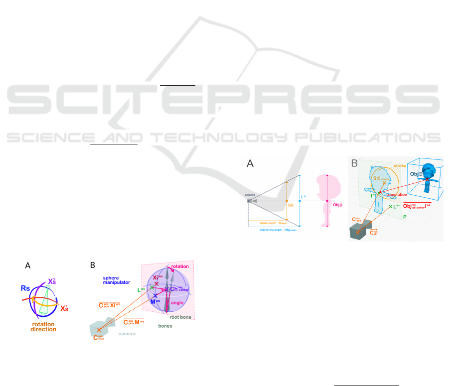
5.4 Sphere Manipulator
The sphere manipulator is constructed of three dif-
ferent strokes: one circle stroke Rs that indicates the
body part to edit and two crossing curved strokes X
1
s
and X
2
s
that show the rotation direction.
5.4.1 Body Part Selection
To select the right chain to edit, we use the same
method as in 5.3.1, but we use the center of the bound-
ing box of the circle stroke in world space Rs
ws
center
and
the center of the bounding box of each editable bone
chain C h
ws
center
instead.
5.4.2 Rotation Computation
Once the right bone chain has been selected, we must
estimate the required bone rotation according to the
user input sketches. First, we correct the position of
the sphere manipulator by translating the three strokes
to make the circle bounding box center Rs
ws
center
over-
lap the selected chain bounding box center Ch
ws
center
.
We also compute the intersection point Xi
ws
between
the two cross strokes X
1
s
and X
2
s
. Then, we calcu-
late the intersection points L
ws
k
between the line from
the camera position to the cross point C
ws
pos
Xi
ws
and
the sphere S with the bone chain bounding box center
Ch
ws
center
as center and the chain length Cl as diame-
ter. We do the same operation to find the intersection
points M
ws
k
of the line from the camera to the bone
bounding box center C
ws
pos
Ch
ws
center
with the previous
sphere S. For now, we select by default the intersec-
tion point M
ws
that is the closest to the camera. The
desired rotation is represented by the angle between
the vector
−−−−−−−→
M
ws
0
Ch
ws
center
going from the intersection
point of the chain bounding box center to the chain
bounding box center and the vector
−−−−−−−→
L
ws
0
Ch
ws
center
that
goes from the intersection point to the chain’s bound-
ing box center. This process is illustrated in figure 6.
Figure 6: Sphere manipulator description (A). Computation
of the bone chain rotation (B).
Using these two vectors, we are able to build a
quaternion representing the required rotation. This ro-
tation is applied back to the root bone of the chain.
5.5 Global Posing
With the global posing tool, artists can set the object’s
global position by drawing the area it should occupy
on the 2D screen. To do so, we compute the accurate
depth of the 3D character according to the size of the
stroke in screen space and the real character size in
world space.
The algorithm extracts the 3D object and the 2D
stroke bounding boxes. Then, it builds a first bound-
ing box vector
−−−→
Ob j
cs
bb
for the 3D object and a sec-
ond one for the stroke
−→
S
cs
bb
in camera space coordi-
nates. Several modes are available to build the bound-
ing box vectors: height, width and full. For exam-
ple, in height mode, we only take the vector from
the lowest (0,y
min
, 0) to the highest bounding box
point (0, y
max
, 0). In width mode, we construct the
vector with the leftmost (x
min
, 0, 0) and the rightmost
(x
max
, 0, 0) points. By default, we select the vector
from the left bottom shallowest point (x
min
, y
min
, z
min
)
to the right top deepest (x
max
, y
max
, z
max
) point of the
bounding box. Modes can be specified for each char-
acter in its JSON description file. According to the
input 3D model, some modes can be more relevant
than others. For example, if the model is particularly
tall and thin, it could be more useful to only take into
consideration the bounding box’s height to compute
the matching depth. On the other hand, if the charac-
ter is significantly longer on the x axis, like the whale
in figure 8, we should use the width mode to make the
computation more accurate.
Figure 7: Computation of the depth of the character in cam-
era space (A). Computation of the final position of the char-
acter and its translation vector (B).
We compute the depth of the character in camera
space Char
cs
depth
by using basic projection rules (figure
7-A). We multiply the norm of the character bounding
box vector
−−−→
Ob j
cs
bb
by the depth of the stroke object in
camera space S
cs
depth
. Then, we divide the result by the
norm of the stroke bounding box vector
−→
S
cs
bb
.
Char
cs
depth
=
k
−−−→
Ob j
cs
bb
k ∗ S
cs
depth
k
−→
S
cs
bb
k
(3)
The system builds a camera centered landmark
Assisting Storyboarders in Expressive 3D Pose Creation with a 2D Sketch-based Interface
131

Figure 8: Comparaison of our posing method with the classical IK-FK method on pose creation tasks. The table surveys the
time required to create the pose, the number of manipulations required and the number of camera angle changes.
point L
cs
(0, 0,Char
cs
depth
) with the previously com-
puted depth. The point is transposed into world space
coordinates L
ws
. To find the final position of the 3D
object, we compute the intersection point I
ws
between
the line C
ws
pos
S
ws
bb center
from the camera position to the
bounding box center of the stroke with the plane par-
allel to the camera clipping plane passing by the trans-
posed landmark point L
ws
. The translation vector
comes from the current bounding box center to the
intersection point
−−−−−−−−−→
Ob j
ws
bb center
I
ws
. This translation is
applied to the 3D object in the digital content creation
tool (figure 7-B).
6 RESULTS AND APPLICATIONS
Our system was integrated into Blender and tested us-
ing a pen tablet on 4 characters (figure 8). We created
the same poses using the classical method with in-
verse and forward kinematic controllers and with our
sketch posing method. The goal was to evaluate the
benefits and the flaws of our technique. We have sur-
veyed the time required to create the pose as well as
the number of manipulations on the character and the
changes of the view angle.
The results showed that our system needs less user
interventions: 12 with our method versus 24 with the
classical method on the third pose. It also requires less
time to create the pose: 6 seconds versus 21 seconds
on a simple pose and 62 seconds versus 296 seconds
on a more complex pose. There were no camera view
changes using our method, as one of the constraints
was to provide a monocular interface.
The work exposed here provides several advances
that make it contribute to the actual state of the art.
Our sketch posing tool is one of the few systems that
integrates 3D notions into the storyboarder’s work-
flow in an intuitive way, while the majority of the ex-
isting tools tend to ignore the issue of 3D, or to impose
unnatural and complex interfaces. By following the
storyboarder’s constraints, we developed a tool that is
more suited to his needs. The user does not have to ro-
tate around the model to add more depth information,
unlike in (Guay, 2015)’s method. In addition, our tool
remains flexible and adaptable, as it can be used with
various morphological types, unlike methods relying
on databases, such as (Akman et al., 2020). As op-
posed to (Gouvatsos, 2018)’s technique, our method
is automatic and works in real time. The originality
of our technique also comes from the combination of
several sketch abstractions integrated into three tools
that the user can pick instantly according to his needs.
In that way, our system can find applications in
the 3D animation industry, as it would be particularly
suited to layout, previz and storyboard departments
where it could form a practical ideation tool.
7 CONCLUSIONS AND FUTURE
WORKS
Although this tool allows to quickly prototype poses,
it does not offer as many levels of precision as the
classical controller based technique, which affects the
quality of the resulting poses. Thus, some points
could be deepened in future works to improve our
method. For now, our sketch posing system doesn’t
consider how the character interacts with the 3D en-
vironment. As (Lin et al., 2012) did in their research,
we should try to implement new constraints in or-
der to avoid collisions with the other 3D objects of
the scene and use them to resolve depth ambigui-
ties. Moreover, our tool doesn’t take into account the
possible movements a character can do according to
his morphology, as described in some studies, such
as (Lee and Chen, 1985). Thus, in the future, we
will pursue the development of our work by adding
constraints to prevent the generation of implausible
poses. Finally, handling the case of facial expression
could be worthwhile. When our method will be sig-
nificantly improved, we will have to make a better
study of its impact on the creative process by orga-
nizing testing sessions with storyboard artists and by
evaluating in a more relevant way the aesthetic and
technical quality of the resulting poses.
HUCAPP 2022 - 6th International Conference on Human Computer Interaction Theory and Applications
132

ACKNOWLEDGEMENTS
We would like to thank Superprod Studio for giving
us the opportunity to experiment our tool on their 3D
asset (figures 2, 3, 7 and 8). We also thank the sto-
ryboarder and layout artists who agreed to participate
in our interviews and offered us important informa-
tion about their way of working. Finally, we thank
the Blender Foundation for the use of the Rain Rig to
test our system (figures 1 and 8).
REFERENCES
Akman, A., Sahilliog, Y., and Sezgin, T. M. (2020). Gen-
eration of 3D Human Models and Animations Using
Simple Sketches. Canadian Human-Computer Com-
munications Society, Proceedings of Graphics Inter-
face 2020:9.
Bessmeltsev, M., Vining, N., and Sheffer, A. (2016). Ges-
ture3D: posing 3D characters via gesture drawings.
ACM Transactions on Graphics, 35(6):1–13.
Choi, M. G., Yang, K., Igarashi, T., Mitani, J., and Lee, J.
(2012). Retrieval and Visualization of Human Motion
Data via Stick Figures. Computer Graphics Forum,
31(7):2057–2065.
Douglas, D. H. and Peucker, T. K. (1973). Algorithms for
the reduction of the number of points required to rep-
resent a digitized line or its caricaturee. Cartograph-
ica: The International Journal for Geographic Infor-
mation and Geovisualization, 10(2):112–122.
Gouvatsos, A. (2018). 3D Storyboarding for Modern Ani-
mation. Thesis, University Bournemouth.
Guay, M. (2015). Animation de personnages 3D par le
sketching 2D. Theses, Universit
´
e Grenoble Alpes.
Hahn, F., Mutzel, F., Coros, S., Thomaszewski, B., Nitti,
M., Gross, M., and Sumner, R. W. (2015). Sketch
abstractions for character posing. In Proceedings of
the 14th ACM SIGGRAPH / Eurographics Symposium
on Computer Animation, pages 185–191, Los Angeles
California. ACM.
Jain, E., Sheikh, Y., and Hodgins, J. (2009). Leveraging the
talent of hand animators to create three-dimensional
animation. pages 93–102.
Lee, H.-J. and Chen, Z. (1985). Determination of 3d human
body postures from a single view. Computer Vision,
Graphics, and Image Processing, 30(2):148–168.
Lin, J., Igarashi, T., Mitani, J., Liao, M., and He, Y. (2012).
A sketching interface for sitting pose design in the vir-
tual environment. IEEE Transactions on Visualization
and Computer Graphics, 18(11):1979–1991.
Lin, Y. (2006). 3D Character Animation Synthesis From 2D
Sketches. page 7.
Low, S. E. (2014). Sketch-Based Animation Tool for
Character Animation Intergrating into a Production
Pipeline. Master’s thesis, Texas A & M University.
Lv, P., Wang, P. J., Xu, W. W., Chai, J. X., Zhang, M. M.,
Pan, Z. G., and Xu, M. L. (2015). A Suggestive Inter-
face for Sketch-based Character Posing. page 11.
Mahmudi, M., Harish, P., Le Callennec, B., and Boulic, R.
(2016). Artist-oriented 3D character posing from 2D
strokes. Computers and Graphics, 57(C):81–91.
Mao, C., Qin, S., and Wright, D. (2006). Sketching-out vir-
tual humans: from 2d storyboarding to immediate 3d
character animation. In Advances in Computer Enter-
tainment Technology.
Mueller, J. E. An Introduction to the Hydraulic and Topo-
graphic Sinuosity Indexes1. Annals of the Association
of American Geographers, 58(2):371–385.
Seki, S. and Igarashi, T. (2017). Sketch-based 3D hair pos-
ing by contour drawings. In Proceedings of the ACM
SIGGRAPH / Eurographics Symposium on Computer
Animation, pages 1–2, Los Angeles California. ACM.
Thorne, M. and Burke, D. (2004). Motion doodles: an in-
terface for sketching character motion. ACM Transac-
tions on Graphics, 23:424–431.
Wei, X. K. and Chai, J. (2011). Intuitive interactive human-
character posing with millions of example poses.
IEEE Computer Graphics and Applications.
Xiao, J., Tang, Z., Feng, Y., and Xiao, Z. (2015). Sketch-
based human motion retrieval via selected 2D geomet-
ric posture descriptor. Signal Processing, 113:1–8.
¨
Oztireli, C., Baran, I., Popa, T., Dalstein, B., Sumner, R.,
and Gross, M. (2013). Differential blending for ex-
pressive sketch-based posing. pages 155–164.
Assisting Storyboarders in Expressive 3D Pose Creation with a 2D Sketch-based Interface
133
