
Real-time Rendering of Indirectly Visible Caustics
Pierre Moreau
a
and Michael Doggett
b
Faculty of Engineering, Lund University, Lund, Sweden
Keywords:
Real-time, Ray Tracing, Caustics Rendering.
Abstract:
Caustics are a challenging light transport phenomenon to render in real-time, and most previous approaches
have used screen-space accumulation based on the fast rasterization hardware of GPUs. This limits the posi-
tion of photon collection points to first hit screen space locations, and leads to missing caustics that should be
visible in a mirror’s reflection. In this paper we propose an algorithm that can render caustics visible via spec-
ular bounces in real-time. The algorithm takes advantage of hardware-accelerated ray tracing support found in
modern GPUs. By constructing an acceleration structure around multiple bounce view ray hit points in world
space, and tracing multiple bounce light rays through the scene, we ensure caustics can be created anywhere
in the scene, not just in screen space. We analyze the performance and image quality of our approach, and
show that we can produce indirectly visible caustics at real-time rates.
1 INTRODUCTION
Caustics are a natural phenomenon created by the
concentration of light as it is reflected and trans-
mitted through objects. While many techniques ex-
ist to generate these lighting effects in images of
three dimensional scenes, generating them in real-
time for interactive applications is challenging. A
popular approach to achieving real-time performance
is the use of screen-space algorithms, but these algo-
rithms come with limitations, in particular not work-
ing well for scenes with reflective surfaces and semi-
transparent objects. For consistent viewing of ren-
dered images, lighting effects like caustics need to
remain constant. Screen-space accumulation tech-
niques can lead to inconsistent renderings with light-
ing effects switching on and off, or even missing in
mirrors, as can be seen in Figure 1 for the technique
by Kim (2019).
Caustics have always been an important feature
of rendering research and go back to early backward
ray tracing techniques (Arvo, 1986). More recent ap-
proaches have used the rasterization pipeline and off-
screen buffers for a range of techniques such as caus-
tic mapping (Hu and Qin, 2007; Shah et al., 2007;
Szirmay-Kalos et al., 2005; Wyman and Davis, 2006).
While these techniques create good approximations,
many issues remain, including sampling rates, large
a
https://orcid.org/0000-0003-3916-1250
b
https://orcid.org/0000-0002-4848-3481
numbers of photons, and potential coherency prob-
lems during animation. With the recent introduc-
tion of hardware-accelerated ray tracing, new ap-
proaches (Kim, 2019; Ouyang and Yang, 2020a; Yang
and Ouyang, 2021) take advantage of this to create
high-quality caustics, but still do not handle caustics
not directly visible.
Screen-space accumulation techniques that only
collect lighting contributions at locations that are di-
rectly visible by the current camera are always lim-
ited in terms of correctly rendering a scene. For the
case of a scene where a caustic is visible via its re-
flection in a mirror, the lighting contributions would
be collected on the mirror itself. This means the pho-
tons responsible for the caustic would need to be re-
flected off the diffuse surface and into one of the col-
lection locations on the mirror. This is unlikely as
the BSDF sampling will have a low chance at return-
ing a direction towards the mirror in most cases and
that direction needs to be within the tight lobe of a
rough mirror, and outright impossible in the case of
a perfectly-specular mirror. Furthermore most real-
time caustic-rendering techniques stop the light path
at the first diffuse hit, preventing the caustic photons
from ever reaching that mirror and being accounted
for; this cut is performed for performance reasons as
caustic paths with two or more diffuse hits will have
a more subtle contribution than caustic paths with a
single diffuse hit.
This paper proposes to collect photons, on dif-
Moreau, P. and Doggett, M.
Real-time Rendering of Indirectly Visible Caustics.
DOI: 10.5220/0010777800003124
In Proceedings of the 17th International Joint Conference on Computer Vision, Imaging and Computer Graphics Theory and Applications (VISIGRAPP 2022) - Volume 1: GRAPP, pages
39-48
ISBN: 978-989-758-555-5; ISSN: 2184-4321
Copyright
c
2022 by SCITEPRESS – Science and Technology Publications, Lda. All rights reserved
39
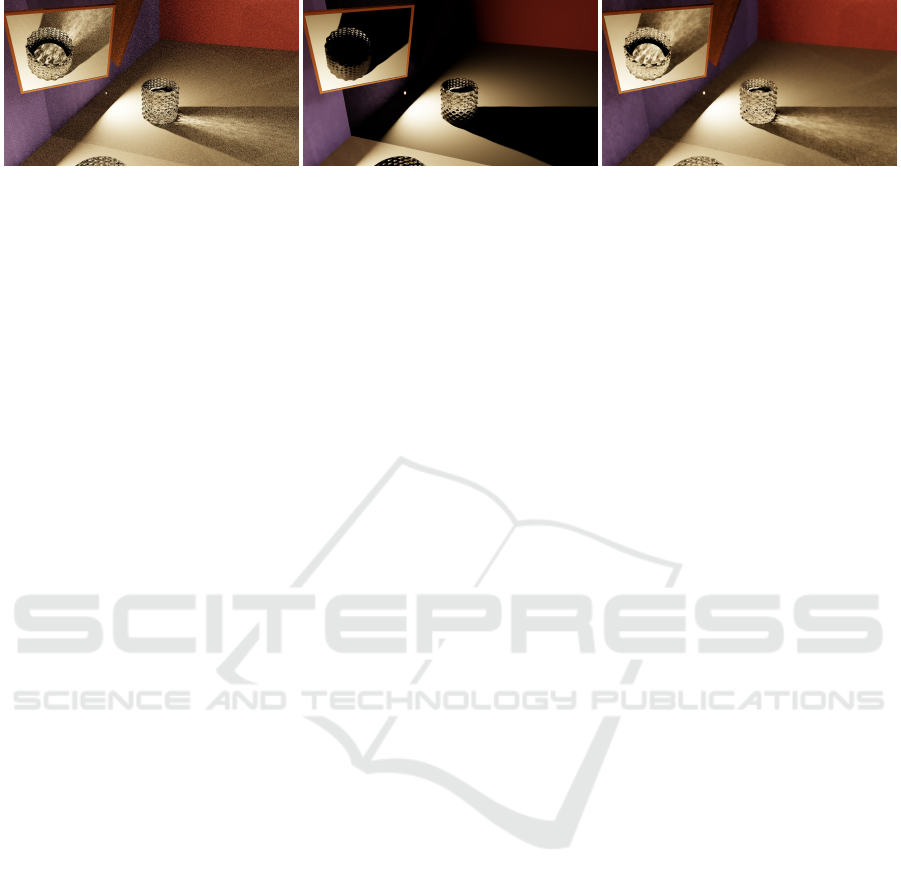
(a) Reference. (b) Kim (2019), 24.7 ms. (c) Our approach, 25.6 ms.
Figure 1: This figure shows a challenging setup for real-time caustics which are only visible via a chain of specular events,
such as mirror reflections. As Kim (2019) accumulates photon contributions in screen space, contributions for anything seen
via this perfectly specular mirror will be collected on the mirror itself requiring them to come from one very specific direction
in order to have any impact; the caustics visible via the different mirrors are completely missing as a result. Our new approach
can handle the caustics since its accumulation is based around a world-space acceleration structure. This scene was rendered
at 1920 × 1080 with a path length of 6 segments using different algorithms; (a) uses 125k samples per pixel (spp), (b) 1 spp
and 14M light paths, and (c), our temporal approach, 1 spp and 1M light paths.
fuse surfaces, at viewing ray hit points, found using
hardware-accelerated ray tracing. At each hit point
for a light path, a Bounding Volume Hierarchy (BVH)
node is created and constructed into a BVH tree using
DirectX Raytracing. By creating a full scene BVH,
the algorithm is not limited to screen-space- or view-
frustum-based images. We then query the BVH us-
ing the algorithm by Evangelou et al. (2021). We also
use ray differentials for appropriate sizing of the BVH
nodes, and use the BVH structure as a temporal cache
for filtering. Our key contribution is enabling real-
time indirect caustics, by combining view and light
rays with a custom BVH, all using ray tracing hard-
ware acceleration.
2 RELATED WORK
Tracing light rays or photons from a light source to
an opaque surface and accumulating light intensity on
a surface has been a common approach to generat-
ing caustics (Arvo, 1986; Jensen, 2001). Generating
caustics in real-time can be done by reproducing pho-
ton mapping on a GPU (McGuire and Luebke, 2009),
but these approaches are expensive and not capable of
generating highly accurate caustics.
Another method for generating caustics in real-
time is caustic maps. Caustic maps are generated by
first making a photon buffer by emitting photons from
the light’s perspective into a two-dimensional buffer
similar to shadow maps. The photons from the pho-
ton buffer are then drawn into the caustic map, which
is projected onto the final image. Szirmay-Kalos
et al. (2005) and Wyman and Davis (2006) improved
quality by increasing photon count and Wyman and
Nichols (2009) created a hierarchical caustic map,
that adaptively processed only the necessary parts of
the photon buffer. But caustic maps still limit the lo-
cations that photons can be captured at, and the pro-
jection of high photon counts into the caustic map
quickly becomes expensive when trying to improve
image quality.
With the advent of hardware accelerated ray trac-
ing, several new approaches to real-time rendering of
caustics have made use of this feature. Kim (2019)
uses projection volumes to direct photons towards
semi-transparent objects to create photon maps lim-
iting visible caustics to these projection volumes.
Gruen (2019) focuses on creating volumetric wa-
ter caustics in single-scattering participating media
where a water surface casts a caustic on an underlying
surface, but it does not handle refracted and then re-
flected light rays. Ouyang and Yang (2020a,b); Yang
and Ouyang (2021) introduce caustic meshes for gen-
eral caustics, but their method requires two passes for
reflected and refracted caustics, and only caustics in
the current viewport can be seen in this case. They
further combine their technique with cascaded caustic
maps for water caustics, but are focused on the caustic
on the surface underlying the water. Wang and Zhang
(2021) only trace rays after intersecting with a semi-
transparent object, at which point it fires photons into
a caustic map to layer onto the final image. By using a
caustic map, their algorithm has similar limitations to
screen-space techniques. While all these recent meth-
ods address caustics, some are screen space limited,
and none of them address the issues of indirect caus-
tics where photons must be accumulated outside the
view frustum to correctly handle reflected caustics,
and caustics behind semi-transparent objects.
Evangelou et al. (2021) present a fast radius search
by mapping the problem to GPU ray traversal and
can therefore take advantage of ray tracing hardware.
In our algorithm, we utilise their approach to query
the BVH used when accumulating photons as well as
when reusing the accumulation results in later frames.
GRAPP 2022 - 17th International Conference on Computer Graphics Theory and Applications
40

They evaluate their algorithm by using it for pro-
gressive photon mapping (Hachisuka et al., 2008) by
building an acceleration structure around the photons
traced from the light, whereas in our algorithm we
build the acceleration structure around the camera ray
hit points, where photons are collected.
3 ALGORITHM
Unlike screen-space techniques, our approach accu-
mulates photons in a world-space caching structure
based on arbitrary points and their surroundings. The
size of that area is uniquely computed at each caching
point, enabling support for fine-detail caustics.
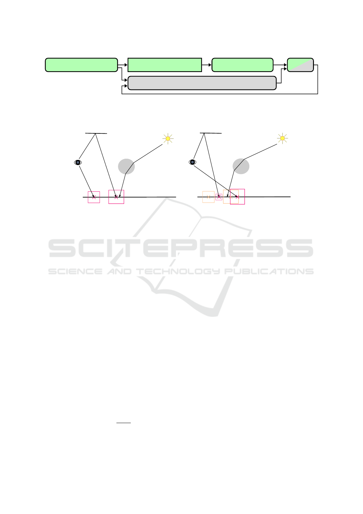
The stages of our algorithm are shown in Figure 2.
The first stage is a path tracer which identifies the first
diffuse hit found along each camera path where light
contributions will later be collected, similar to pro-
gressive photon mapping (Hachisuka et al., 2008). In
our algorithm we refer to these hit points as collec-
tion points. An acceleration structure is then created
around the collection points, and light paths are traced
to accumulate light intensity at each collection point.
Finally the output is resolved before being processed
using a spatiotemporal filter.
We will be using the following notation: c
i
refers to a collection point in frame i, C
i
refers to all collection points present in frame
i. A collection point has the following attributes:
p world position
τ camera sub-path throughput
r search radius
n world normal
I accumulated radiant intensity
m material ID
L
o
exitant radiance
˜
L
o
interpolated exitant radiance
ˆ
L
o
weighted contributions from previous collec-
tion points
Figure 3 shows an overview of our setup with
camera and light paths. When path tracing, the col-
lection points are selected based on the BSDF com-
ponent that was evaluated for generating the reflected
ray at a hit: if a diffuse component was used, then we
create a collection point at the hit point. In Figure 3,
this is the case for p
1
and m
2
but not m
1
as it sampled
the specular component of the mirror.
Selecting a Search Radius. As collecting from a
single point in space is infeasible in practice, we in-
stead gather from a surrounding area. We use the ra-
dius of the disk enclosing the pixel footprint in world
space for the collection points at primary hits, as a
reasonable middle ground between over-blurring and
light leakage, and too restrictive radii that would ig-
nore most light paths.
To compute the pixel footprint for collection
points at secondary hits, we use half the width of ray
cones as described by Akenine-Möller et al. (2021) as
our search radius, and take the BSDF roughness into
account as described in their Section 4. The ray cones
computation is cheaper than ray differentials (Igehy,
1999), and is necessary for texture level of detail cal-
culation.
Creating the Acceleration Structure. We use a
similar approach to Evangelou et al. (2021) for ac-
celerating radius searches. In their work they recom-
mended building the acceleration structure around the
photons rather than around the collection points, as
atomics can then be avoided for updating the accumu-
lated contributions at each collection point, as having
overlapping collection points (for example when the
same area is visible both directly and via a mirror) can
noticeably decrease performance. The overhead from
using atomics is about 5%; please see Section 3.2 for
more details.
In contrast, we build the acceleration structure
around the collection points for the following reasons:
• more predictable quality reduction when decreas-
ing the number of collection points to improve
performance, than reducing the number of pho-
tons stored;
• the light contributions accumulated at collection
points can be easily reused over multiple frames,
as presented in Section 3.1.
• building around photons forces the use of the
largest radius for each of them, which can be
costly as radii depend on location and intersected
shapes and materials;
As numerical precision errors might result in the
hit position being slightly above or below the sur-
face, we gather from a cylinder rather than from a
disk, similarly to most photon mapping methods. The
cylinder is aligned along c
i
.n, uses the same radius
c
i
.r, and has its height set to a tenth of c
i
.r. We then
compute the smallest AABB containing that cylinder
and use it as the primitive around which the accelera-
tion structure is built.
Tracing Light Sub-paths. The algorithm does not
depend on how the set of light sources and individ-
ual light sources are being sampled, so different tech-
niques can be used here such as the recent works by
Kim (2019) or by Ouyang and Yang (2020a); Yang
and Ouyang (2021).
Real-time Rendering of Indirectly Visible Caustics
41
Identify collection points Build collection point AS
Trace light sub-paths
Resolve
Temporal feedback loop
Adapt past accumulations to current collection points
Figure 2: An overview of the different steps of our approach, with all boxes with a green colour constituting the basic algo-
rithm, and the grey ones were either added or modified to support temporal reuse. All steps are performed in programmable
shaders, except for the rectangle with non-rounded corners, which is instead taken care of by the API.
p
1
p
0
q
0
q
1
q
2
q
3
mirror
diffuse
m
0
m
1
m
2
p
1
p
0
q
0
q
1
q
2
q
3
mirror
diffuse
m
0
m
1
m
2
frame i
frame i+1
Figure 3: An overview of our indirect-caustic algorithm. Camera paths, p, m, are traced to the first diffuse surface intersection,
where collection points (shown as red boxes) are created and placed in a BVH. Then light paths, q, are traced via specular
intersections and collected. The path m will generate an indirect caustic in the final image. On the right half of the image
is frame i + 1, which shows how new collection points are created when the camera rays change, but collection points from
previous frames can still be reused.
Regardless of the chosen method(s) for sampling
and tracing the light sub-paths, every time the sub-
path hits a surface we will query and selectively up-
date all collection points that contain this hit. As
we leverage a hardware accelerated BVH and ray
tracing API, this is implemented by tracing a very
short ray (Wald et al., 2019), starting from the hit,
against the acceleration structure storing our collec-
tion points. For each intersected collection point,
we first check that the hit is actually located within
the collection cylinder and that its material identifier
matches the one stored in the collection point, before
accumulating in c
i
.I the flux carried by the photon
into radiant intensity reflected towards the vertex prior
to the collection point in the camera sub-path (e.g. to-
wards m
1
if accumulating at m
2
).
Resolving. Before presenting the results to the user,
the accumulated radiant intensity needs to be trans-
formed into radiance, and take account of the through-
put of the camera sub-path connecting a collection
point to a pixel. This is summarised in the following
equation:
c
i
.L
o
= c
i
.τ
c
i
.I
πc
i
.r
2
(1)
3.1 Temporal Reuse
A benefit of our approach is that we can reuse the ex-
act same accumulated radiant intensity and just mul-
tiply it by the new camera sub-path throughput when
a directly-visible caustic moves behind a transparent
object for example, as only the light sub-path contri-
bution gets accumulated. Whereas this accumulated
data would usually be discarded by filters on occlu-
sions or disocclusions, having the data stored in world
space allows us to reuse it if appropriate.
The reuse happens in two separate steps: first we
gather contributions from all past collection points lo-
cated near current ones, and second, past and present
contributions are combined together during the re-
solve step using an exponential moving average with
α = 0.8:
c
i
.
˜
L
o
= αc
i
.
ˆ
L
o
+ (1−α)c
i
.L
o
(2)
Reusing Past Accumulations. This takes place be-
tween the identification of collection points in the cur-
rent frame and resolve. If keeping two acceleration
structures in memory is an issue, this step should be
performed before updating the collection point accel-
eration structure for the current frame.
GRAPP 2022 - 17th International Conference on Computer Graphics Theory and Applications
42

We query all collection points c
i−1
∈ C
i−1
con-
taining c
i
. p, by tracing a very short ray originating
from c
i
. p against the acceleration structure built dur-
ing the previous frame. For each intersected collec-
tion point c
i−1
satisfying the system of equations (4)
(similar to a bilateral filter), its interpolated radiance
c
i−1
.
˜
L
o
weighted by a Gaussian kernel w(c
i−1
) of
width σ =
3
4
c
i
.r is accumulated into c
i
.
ˆ
L
o
:
w(c
i−1
) = exp
−kc
i
. p − c
i−1
. pk
2
2σ
2
(3)
kc
i−1
. p − c
i
. pk ≤ c
i
.r
c
i−1
.n · c
i
.n ≥ 0.9
c
i−1
.m = c
i
.m
(4)
3.2 Implementation Details
General Constraints. If path tracing is used by
an application, care needs to be taken to avoid
the path tracer evaluating the same paths as the
photon-based approach, or to weigh them appropri-
ately. As we simply add the results from both ap-
proaches, we prevent the path tracer from evaluating
paths containing at least one diffuse and one specu-
lar bounce as those will be handled by the photon-
based approach. Using Heckbert’s light transport no-
tation (Heckbert, 1990), this corresponds to paths of
the form ES*D(S|D)*S(S|D)*L.
In all presented results, the search radius was
capped to 5 mm as a middle ground between perfor-
mance of the light tracing stage and quality.
Performance Improvements. For the first stage of
the pipeline, we found that storing all the data asso-
ciated to our caching approach as soon as a suitable
collection point was identified, rather than at the end
to minimise control flow divergence, improved the
performance of that stage from 20 ms down to about
4 ms. This is due to not having to keep all that data
live accross the tracing of path segments.
As current APIs do not expose atomic additions
for floats, we first implemented the contribution ac-
cumulation using atomic compare-and-swap within a
loop, resulting in a 15% overhead compared to no
atomics. By instead using fixed-point values and in-
teger atomic add, the overhead was reduced to 5%.
As the accumulated values are well below 1, we only
used 4 digits for the decimal part and the remaining
28 for the fractional part.
4 RESULTS
We implemented our approach on top of
Kim’s (2019), inside the Falcor (Benty et al.,
2020) 4.3 framework using the DirectX 12 and
DirectX Raytracing API. All results were obtained
on an NVIDIA Geforce RTX 3080 with NVIDIA’s
471.96 drivers, and rendered at 1920 × 1080 with a
maximum path length of 6 segments and using 1024
2
light paths, unless mentioned otherwise. Spatiotem-
poral Variance-Guided Filtering (SVGF) (Schied
et al., 2017) was used to filter the computed images
before presenting them to the user.
In the following section we will be using the fol-
lowing abbreviations for methods: OurBasic which
refers to our basic algorithm described in Section 3
(i.e. without the temporal component) and integrated
with a path tracer as described in Section 3.2, and
OurTemporal which is our full algorithm (i.e. Our-
Basic plus the temporal component described in Sec-
tion 3.1).
All scenes, besides the ones shown in Figure 7,
use a similar template of a closed box whose left and
back wall and ceiling are specular, with the other parts
being diffuse. This box contains a simple emissive
mesh as the only light source, a transparent object,
and a mirror. Of these scenes, four have animations
of different types: animated camera (AC), animated
light (AL), animated geometry (AG; it is the trans-
parent sphere), and all animated (AA; it combines all
previous animations). They are all 10 seconds long
and animated at 30 fps. Unless mentioned otherwise,
the specular walls and ceiling in the animated scenes
have a roughness R of 0.08.
The Bistro Exterior and Bistro Interior scenes
used in Figure 7 were modified to limit the number
of emissive triangles by setting the emissivity to 0 for
most light sources. Additionally in Bistro Interior,
light paths were only traced from the lamps placed on
tables. To more easily showcase caustics, transparent
objects were added on the tables in Bistro Exterior
while some of the glasses were removed from Bistro
Interior to make more room on the tables. In both
scenes, the windows of the bistro were changed from
a very rough glossy surface into a specular mirror.
The source code and the videos can be found on
the project page
1
.
4.1 Performance
To evaluate the performance of our approach, we ran
it on different types of animations to see their impact.
1
https://fileadmin.cs.lth.se/graphics/research/papers/
2022/indirectly_visible_caustics/
Real-time Rendering of Indirectly Visible Caustics
43
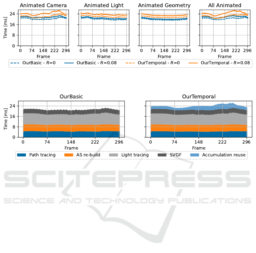
Figure 4: Measuring the total frame time taken by our basic and temporal algorithms for different types of animations. For
comparison a path tracer at equal quality would require about 175 spp and take between 2.5 and 3 seconds; this was measured
for equal
F
LIP-mean on AC@150 and AC@298.
Figure 5: Highlighting the performance of the main stages of the algorithm during the animation in the scene AC. The
identification of collection points is performed during the path tracing step, and the G-buffer generation time (a constant
0.6 ms) was also included under the Path tracing step, while the resolve stage (a constant 0.4 ms) was included under the
SVGF step. 90% of the re-build time is spent on the bottom level acceleration structure. Not part of these plots, there is an
additional 0.27 ms per frame from tonemapping and other miscellaneous operations to reach the timings presented in Figure 4.
Note that accumulation reuse could be run concurrently to re-building the acceleration structure and tracing the light paths.
Looking first at the total frame times presented
in Figure 4, we can see that the cost of our ap-
proaches remains relatively constant throughout the
light and geometry animations. Larger changes can
be observed during the camera animation and seem
to mostly correspond to changes in the number of
bounces before hitting a diffuse surface from the cam-
era. Most of that time variation comes from the pass
reusing the accumulated contributions from previous
frames with the current collection points.
Our approach can extend current path tracing-
based frameworks and as such reuse some of the com-
putations already performed there. For example the
identification of collection points can be added to an
existing path tracer to store additional data without
having to re-trace the same rays in a separate pass.
We noted an increase in the cost of that pass from
about 3 ms to about 4 ms when doing so, for a path
tracer ignoring caustic paths. This combined cost is
presented in Figure 5, along with the cost of the other
steps.
The largest part of the cost of accumulation reuse
and light tracing comes from tracing against the col-
lection point acceleration structure and the invocation
of the intersection and any-hit shader, due to over-
lapping collection points and memory accesses to get
the needed information during the evaluation of the
shaders. For comparison, the same light tracing but
with the accumulation performed in screen space as
presented by (Kim, 2019) takes 1–1.5 ms, as opposed
to the 8.5–9 ms of our approach.
The second most expensive step is rebuilding
the acceleration structure. Rebuilding remains an
expensive operation for any real-time ray tracing-
based workflow, and as such refitting is favoured for
most frames while rebuilding can be performed asyn-
chronously every now and then to keep the tracing
performance optimal. However the location or distri-
bution of collection points seemed to vary too much
between frames, resulting in refitting degrading the
tracing performance by an order of magnitude as soon
as enabled. As the number of collection points de-
pends on the resolution of the rendering and not on the
scene, the cost of this step remained the same in the
Bistro Interior and Bistro Exterior scenes from Fig-
ure 7.
GRAPP 2022 - 17th International Conference on Computer Graphics Theory and Applications
44

Table 1: Average image quality measurements over 10 iterations using SVGF. OurBasic performing slightly better than
OurTemporal after filtering in AL@150 can be explained by both the temporal lag and the contribution of longer paths having
a larger impact on the final image than in the other scenes. Equal Time PT (3 spp) is about the same time as, or slightly more
expensive than, OurTemporal. The standard deviation was at or below 3.7% of the mean in all configurations, except for the
filtered output in AG@10 for OurTemporal which reached 12.7% of the mean.
Scene, FrameID Measure
Equal Time PT (3 spp) OurBasic OurTemporal
Unfiltered Filtered Unfiltered Filtered Unfiltered Filtered
Animated Camera, MAE 0.074 0.041 0.084 0.022 0.065 0.021
Frame 150
F
LIP 0.335 0.292 0.280 0.190 0.241 0.168
Animated Camera, MAE 0.162 0.063 0.150 0.036 0.111 0.028
Frame 298
F
LIP 0.468 0.363 0.410 0.229 0.309 0.179
Animated Light, MAE 0.117 0.084 0.116 0.037 0.088 0.045
Frame 150
F
LIP 0.562 0.520 0.384 0.273 0.335 0.276
Animated Light, MAE 0.077 0.034 0.097 0.029 0.073 0.025
Frame 298
F
LIP 0.323 0.292 0.338 0.261 0.291 0.218
Animated Geometry, MAE 0.127 0.090 0.135 0.036 0.093 0.034
Frame 10
F
LIP 0.465 0.406 0.364 0.204 0.266 0.173
All Animated, MAE 0.077 0.033 0.096 0.020 0.077 0.019
Frame 298
F
LIP 0.228 0.163 0.233 0.110 0.189 0.093
4.2 Quality
As our approach targets real-time applications with
different types of motions, we evaluated the qual-
ity at different points during animations rather than
on still images. We looked at the quality both prior
and after filtering, as well as both numerical (using
mean-absolute error (MAE)) and perceptual (using
F
LIP (Andersson et al., 2020)) methods; all measure-
ments were performed on non-tonemapped outputs.
From Table 1 we can see that both OurBasic and
OurTemporal improve for both metrics in all but one
scene compared to the baseline. OurTemporal fur-
ther improves compared to our basic algorithm in
most scenes, for example in AC@198 the
F
LIP re-
sults are improved by nearly 15%) but also presents
some regressions as can be seen in AG@10 for exam-
ple (though they are within run to run variance).
There are multiple reasons for those regressions
that can be illustrated with results from Table 2. First,
when we reuse accumulated radiance from previous
frames we do not know the length of the light sub-
paths having contributed, so we can end up creating
longer paths than what was specified, as can be seen
for AG@10 in Table 2 at the top of the image where
the mirror contains a reflection of the caustic on the
ground, but that caustic is missing from the refer-
ence. This can be seen as an advantage, as longer
paths can be created at no additional cost. A second
one, which can be seen in the caustic in AA@298 for
OurTemporal, is ghosting artefacts due to the tempo-
ral reuse simply relying on an exponential moving av-
erage; Equal time PT and OurBasic also suffer from
some ghosting introduced by SVGF, but it is not as
noticeable. Finally, there is a conflict between the
two temporal reuse methods, our reuse at the collec-
tion points and the SVGF’s one: as new regions be-
come visible, our temporal reuse will end up creating
two different noise levels for a given surface (the more
converged one, which was visible for several frames,
and the newly uncovered one with very few samples)
which will be interpreted by SVGF as two different
regions making them more visually distinct.
Another important note is that SVGF relies on
motion vectors which are rarely readily available for
light patterns such as caustics or shadows, or reflec-
tions or refractions, all of which are found all over
these scenes. A recent approach by Zeng et al. (2021)
shows promise regarding glossy reflections.
Temporal stability is sometimes improved in real-
time applications by performing the filtering after
tonemapping rather than before, though at the cost
of image quality. This can however result in differ-
ent samples being merged together due to no longer
appearing distinct enough to the filter, such as the
few caustic samples in the second picture of Figure 6
which were mostly blurred out. Thanks to our ap-
proach providing more samples, it can be used along
that filtering trick.
Apart from the previously-mentioned ghosting in
OurTemporal, the temporal quality depends strongly
on the light sampling algorithm used and better results
could be obtained with Ouyang and Yang (2020a);
Yang and Ouyang (2021).
For temporal results, we refer the reader to our
supplemental video which contains all 4 animations
(using filtering post-tonemapping and R = 0) pre-
sented in this paper, as well as additional combina-
Real-time Rendering of Indirectly Visible Caustics
45
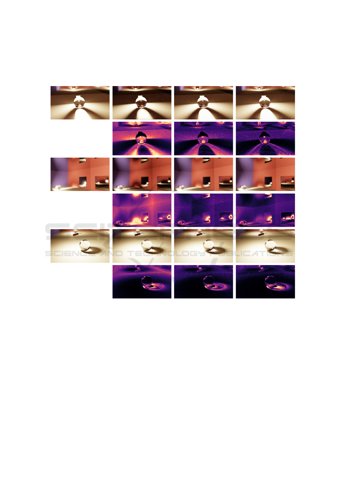
Table 2: Highlighting different scenarios: AC@298 where OurTemporal improved significantly compared to OurBasic,
AG@10 presents a regression for OurTemporal, and AA@298 with an easier to sample caustic for the path tracer. For
each scene, the first row consists of a single frame filtered with SVGF, whereas the second row has error maps generated by
F
LIP (Andersson et al., 2020).
Reference
OurBasic OurTemporalEqual time PT (3spp)
Animated Camera@298Animated Geometry@10All Animated@298
tions for one of the scenes. Additional videos cover-
ing all combinations can be found on the project web-
site (see Section 4).
As mentioned in the introduction, screen-space
accumulation techniques could technically still be
used to collect lighting contributions on glossy sur-
faces. We tried to use the technique by (Kim, 2019)
on such surfaces, but failed to get it to match a ref-
erence unless increasing the roughness past 0.25, at
which point caustics and objects could no longer be
distinguished or seen in the reflections and the mir-
rors.
5 CONCLUSION
Conclusion. In this paper we presented a new al-
gorithm for real-time rendering of detailed caustics
appearing in long specular view paths. Our method
makes use of recent hardware-accelerated ray tracing
for both view and light rays, and for BVH construc-
tion. We create a temporal cache of previous frame
light intensity to improve temporal filtering. Tempo-
ral filtering costs more in frame time, if not performed
asynchronously, but improves image quality in most
cases. Our results show that performance of 20–28 ms
for the box scenes, is possible with temporal filtering
for scenes with reflective surfaces showing caustics
that are not rendered by existing screen-space accu-
GRAPP 2022 - 17th International Conference on Computer Graphics Theory and Applications
46

Figure 6: Unlike path tracing, our approach samples the caustics sufficiently that they do not disappear when filtering after
tonemapping, to improve temporal stability. From left to right:
F
LIP error map for Equal Time PT (2 spp), Equal Time PT
(2 spp), OurTemporal,
F
LIP error map for OurTemporal. These can be compared to the reference image and results obtained
when filtering prior to tonemapping that are found in Table 2.
Figure 7: Our approach can be applied to more complex scenes (left image: 39 ms, path length of 7 segments; centre image:
46 ms, path length of 6 segments) and scales to more intricate caustics (right image, 1 s, path length of 6 segments; 175k spp
for an equal quality path tracer). For the first two images, the main costs are path tracing (17–19 ms), light tracing (8–11 ms),
and AS re-build (6 ms). All three images were rendered using our temporal version, and while the first two were filtered with
SVGF, the last was accumulated over multiple frames.
mulation techniques. Additionally, our approach can
be applied to complex scenes.
Future Work. The variation in collection point lo-
cations from frame to frame depending on the mate-
rial sampling goes against the assumptions made by
current BVH refitting approaches, resulting in low
tracing performance. Temporal filtering of caustics
remains an open issue with one of its challenges be-
ing the obtention of motion vectors for the caustics,
which would help in reducing ghosting artefacts. The
data cached by our approach could be extended to in-
clude, for example, a reservoir to use ReSTIR (Bitterli
et al., 2020) even on surfaces visible via mirror(s).
ACKNOWLEDGMENTS
We thank Jacob Munkberg for valuable insights and
discussions. Pierre Moreau was supported by Veten-
skapsrådet, and Michael Doggett is supported by EL-
LIIT and WASP. The transparent glass used in the
teaser and Figure 7 was made by Simon Wendsche
2
.
The Bistro Interior and Bistro Exterior scenes used in
Figure 7 are courtesy of Amazon Lumberyard (2017).
2
https://byob.carbonmade.com/
REFERENCES
Akenine-Möller, T., Crassin, C., Boksansky, J., Belcour,
L., Panteleev, A., and Wright, O. (2021). Improved
shader and texture level of detail using ray cones.
Journal of Computer Graphics Techniques (JCGT),
10(1):1–24.
Amazon Lumberyard (2017). Amazon Lumber-
yard bistro, open research content archive
(ORCA). http://developer.nvidia.com/orca/amazon-
lumberyard-bistro.
Andersson, P., Nilsson, J., Akenine-Möller, T., Oskarsson,
M., Åström, K., and Fairchild, M. D. (2020).
F
LIP:
A Difference Evaluator for Alternating Images. Pro-
ceedings of the ACM on Computer Graphics and In-
teractive Techniques, 3(2):15:1–15:23.
Arvo, J. (1986). Backward ray tracing. In Developments
in Ray Tracing (SIGGRAPH 86 Course Notes), vol-
ume 12.
Benty, N., Yao, K.-H., Clarberg, P., Chen, L., Kallweit,
S., Foley, T., Oakes, M., Lavelle, C., and Wyman,
C. (2020). The Falcor rendering framework. https:
//github.com/NVIDIAGameWorks/Falcor.
Bitterli, B., Wyman, C., Pharr, M., Shirley, P., Lefohn, A.,
and Jarosz, W. (2020). Spatiotemporal reservoir re-
sampling for real-time ray tracing with dynamic direct
lighting. ACM Trans. Graph., 39(4).
Evangelou, I., Papaioannou, G., Vardis, K., and Vasilakis,
A. A. (2021). Fast radius search exploiting ray trac-
ing frameworks. Journal of Computer Graphics Tech-
niques (JCGT), 10(1):25–48.
Gruen, H. (2019). Ray-guided volumetric water caustics
in single scattering media with dxr. In Ray Tracing
Gems: High-Quality and Real-Time Rendering with
Real-time Rendering of Indirectly Visible Caustics
47

DXR and Other APIs, chapter 14, pages 183–201.
Apress, Berkeley, CA.
Hachisuka, T., Ogaki, S., and Jensen, H. W. (2008). Pro-
gressive photon mapping. In ACM SIGGRAPH Asia
2008 Papers, SIGGRAPH Asia ’08, New York, NY,
USA. Association for Computing Machinery.
Heckbert, P. S. (1990). Adaptive radiosity textures for bidi-
rectional ray tracing. SIGGRAPH Comput. Graph.,
24(4):145–154.
Hu, W. and Qin, K. (2007). Interactive approximate ren-
dering of reflections, refractions, and caustics. IEEE
Transactions on Visualization and Computer Graph-
ics, 13(1):46–57.
Igehy, H. (1999). Tracing ray differentials. In Proceedings
of the 26th Annual Conference on Computer Graph-
ics and Interactive Techniques, SIGGRAPH ’99, page
179–186, USA. ACM Press/Addison-Wesley Publish-
ing Co.
Jensen, H. W. (2001). Realistic Image Synthesis Using Pho-
ton Mapping. A. K. Peters.
Kim, H. (2019). Caustics using screen-space photon map-
ping. In Haines, E. and Akenine-Möller, T., editors,
Ray Tracing Gems: High-Quality and Real-Time Ren-
dering with DXR and Other APIs, chapter 30, pages
543–555. Apress, Berkeley, CA.
McGuire, M. and Luebke, D. (2009). Hardware-accelerated
global illumination by image space photon mapping.
In Proceedings of the Conference on High Perfor-
mance Graphics 2009, HPG ’09, page 77–89, New
York, NY, USA. Association for Computing Machin-
ery.
Ouyang, Y. and Yang, X. (2020a). Generating ray-
traced caustic effects in unreal engine 4, part
1. https://developer.nvidia.com/blog/generating-ray-
traced-caustic-effects-in-unreal-engine-4-part-1/.
Ouyang, Y. and Yang, X. (2020b). Generating ray-
traced caustic effects in unreal engine 4, part
2. https://developer.nvidia.com/blog/generating-ray-
traced-caustic-effects-in-unreal-engine-4-part-2/.
Schied, C., Kaplanyan, A., Wyman, C., Patney, A., Chai-
tanya, C. R. A., Burgess, J., Liu, S., Dachsbacher,
C., Lefohn, A., and Salvi, M. (2017). Spatiotempo-
ral variance-guided filtering: Real-time reconstruction
for path-traced global illumination. In Proceedings
of High-Performance Graphics, HPG ’17, New York,
NY, USA. Association for Computing Machinery.
Shah, M. A., Konttinen, J., and Pattanaik, S. (2007). Caus-
tics mapping: An image-space technique for real-time
caustics. IEEE Transactions on Visualization and
Computer Graphics, 13(2):272–280.
Szirmay-Kalos, L., Aszódi, B., Lazányi, I., and Premecz,
M. (2005). Approximate ray-tracing on the gpu
with distance impostors. Computer Graphics Forum,
24(3):695–704.
Wald, I., Usher, W., Morrical, N., Lediaev, L., and Pas-
cucci, V. (2019). RTX Beyond Ray Tracing: Explor-
ing the Use of Hardware Ray Tracing Cores for Tet-
Mesh Point Location. In High-Performance Graphics
- Short Papers.
Wang, X. and Zhang, R. (2021). Rendering transparent ob-
jects with caustics using real-time ray tracing. Com-
puters & Graphics, 96:36–47.
Wyman, C. and Davis, S. (2006). Interactive image-space
techniques for approximating caustics. In Proceedings
of the 2006 Symposium on Interactive 3D Graphics
and Games, I3D ’06, page 153–160, New York, NY,
USA. Association for Computing Machinery.
Wyman, C. and Nichols, G. (2009). Adaptive caustic maps
using deferred shading. Computer Graphics Forum,
28(2):309–318.
Yang, X. and Ouyang, Y. (2021). Real-time ray traced caus-
tics. In Ray Tracing Gems II, chapter 30, pages 469–
497. Apress, Berkeley, CA.
Zeng, Z., Liu, S., Yang, J., Wang, L., and Yan, L.-Q. (2021).
Temporally reliable motion vectors for real-time ray
tracing. Computer Graphics Forum, 40(2).
GRAPP 2022 - 17th International Conference on Computer Graphics Theory and Applications
48
