Geo-Referenced Occlusion Models for Mixed Reality Applications using
the Microsoft HoloLens
Christoph Praschl
a
and Oliver Krauss
b
Research Group Advanced Information Systems and Technology (AIST), University of Applied Sciences Upper Austria,
Softwarepark 11, 4232 Hagenberg, Austria
Keywords:
Mixed Reality, Augmented Reality, Geo-Referenced Models, Occlusion, CityJson, CityGML, Microsoft
HoloLens.
Abstract:
Emergency responders or task forces can benefit from outdoor Mixed Reality (MR) trainings, as they allow
more realistic and affordable simulations of real-world emergencies. Utilizing MR devices for outdoor situa-
tions requires knowledge of real-world objects in the training area, enabling the realistic immersion of both,
the real, as well as the virtual world, based on visual occlusions. Due to spatial limitations of state-of-the-
art MR devices recognizing distant real-world items, we present an approach for sharing geo-referenced 3D
geometries across multiple devices utilizing the CityJSON format for occlusion purposes in the context of
geospatial MR visualization. Our results show that the presented methodology allows accurate conversion of
occlusion models to geo-referenced representations based on a quantitative evaluation with an average error
according to the vertices’ position from 1.30E-06 to 2.79E-04 (sub-millimeter error) using a normalized sum
of squared errors metric. In the future, we plan to also incorporate 3D reconstructions from smartphones and
drones to increase the number of supported devices for creating geo-referenced occlusion models.
1 INTRODUCTION
The fusion of the real and virtual world is one of
the most crucial aspects, in the context of (outdoor)
Augmented (AR) and Mixed Reality (MR) applica-
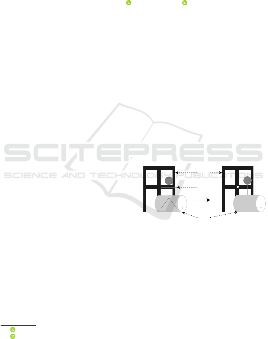
tions. Especially, the visual occlusion of virtual ob-
jects based on the spatial information about the real
world as shown in Figure 1 has a huge impact on
users to completely immerse themselves into the vir-
tual world. For this reason, the present work deals
with methods for exchanging geo-referenced, spatial
information of real world objects between multiple
AR and MR devices to create occlusion models.
Due to the constant development in the field of
AR and MR like head mounted displays (HMD) as
the Microsoft HoloLens 2 (Ungureanu et al., 2020) or
the Magic Leap One (Swaminathan, 2019) more and
more applications in this area became feasible in the
recent years. Especially, when it comes to scopes
like guided working or trainings in indoor scenarios
many workflows have been digitized as product main-
tenance and assembly (Kaplan et al., 2020; Gavish
et al., 2015; Westerfield et al., 2014; De Crescen-
a
https://orcid.org/0000-0002-9711-4818
b
https://orcid.org/0000-0002-8136-2606
Incorrect Occlusion Correct Occlusion
Virtual
Person
Real
World
Barrel
Real
World
House
Figure 1: Occlusion of a virtual person based on the spatial
information of surrounding real world objects, a barrel and
a house. While the barrel is spatially in front of the virtual
person, the house is in the background.
zio et al., 2011) or medical trainings (Ingrassia et al.,
2020; Vergel et al., 2020; Thøgersen et al., 2020;
McKnight et al., 2020). Regardless of that, the uti-
lization of HMDs for MR or AR applications re-
mains largely unaffected for outdoor scenarios. While
nowadays most smartphones are equipped with cellu-
lar as well as GPS modules and for this reason can be
used independently in outdoor scenarios, HMDs as
the before mentioned ones don’t have these technical
features. Thus applications are restricted to local co-
ordinate systems and can’t work with global informa-
tion as geo-referenced objects. In the following, this
Praschl, C. and Krauss, O.
Geo-Referenced Occlusion Models for Mixed Reality Applications using the Microsoft HoloLens.
DOI: 10.5220/0010775200003124
In Proceedings of the 17th International Joint Conference on Computer Vision, Imaging and Computer Graphics Theory and Applications (VISIGRAPP 2022) - Volume 3: IVAPP, pages
113-122
ISBN: 978-989-758-555-5; ISSN: 2184-4321
Copyright
c
2022 by SCITEPRESS – Science and Technology Publications, Lda. All rights reserved
113
also means that information about for example spatial
features can hardly be exchange within a multi-user
setting and every device has to create and update its
own occlusion model of the surrounding environment.
We already tackled the problem of the missing
link to the global position and orientation in a pre-
vious publication (Praschl et al., 2020) by extending
the Microsoft HoloLens with an external GPS, com-
pass and cellular module, which allow us to synchro-
nize the local coordinate systems of multiple devices
within one global system. To the moment, this ex-
tension was only used to synchronize the position of
multiple users and to trigger events based on these po-
sitions in a shared virtual world in the context of out-
door training simulations of emergency response or
disaster operations. Based on the results of this previ-
ous work, we present advanced methodologies to ex-
change geo-referenced information about real world
objects to create occlusion models as the next step to
a spatially unlimited outdoor training system.
2 PROBLEM STATEMENT
While state-of-the-art AR and MR devices as the Mi-
crosoft HoloLens 2 are capable of creating occlusion
models of their surrounding environment in real-time
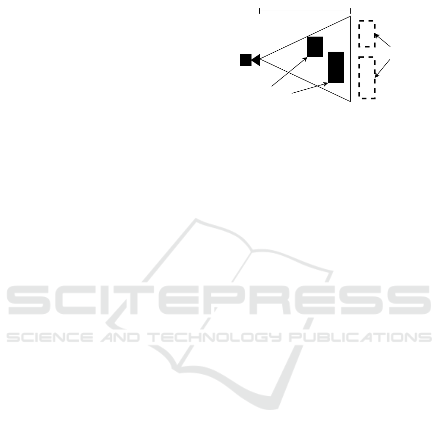
for indoor applications, those devices face their limi-
tations in outdoor scenarios, because of narrow work-
ing distances up to 3.5 meters (H
¨
ubner et al., 2020)
as shown in Figure 2. Next to the working dis-
tances, current head mounted displays in the context
of MR are also not capable of associating their local
coordinate system with a global position and orien-
tation. Therefore such devices face additional lim-
itations for (outdoor) usages in terms of multi-user
purposes, since spatial information can hardly be ex-
changed or merged. This problem can partially be
solved with Microsoft’s MR technology by exchang-
ing the room model (Van Schaik, 2017) or using “Spa-
tial Anchors” (Turner and Coulter, 2019). While the
first approach works well especially for indoor ap-
plications because of many unique and recognizable
spatial features, it does not work that well in out-
door scenarios, where such features are often out of
range of the limited working area. One advantage of
Microsoft’s room models is that the underlying mesh
can be shared across multiple devices, as a trade-off,
it will only be updated within the scan range of the
current device. Scans of other participants as well as
distant, moving objects will not affect the occlusion
model. For this reason, virtual objects may be covered
wrongly. The second concept, the so-called “Spa-
tial Anchors”, allows associating local, visual features
3.5 m
Scan range
Objects out of
range
Objects in
range
Figure 2: Schematic visualization of the scan range with
real world objects in range and such ones that are not in-
cluded into the environment model.
with a decoupled coordinate system and like this en-
ables linking the relative position of other virtual ob-
jects to those anchors. Since “Spatial Anchors” can be
synchronized across multiple devices, it also allows
exchanging associated child objects. One drawback
of this technology is again a spatial limitation of 3 me-
ters to avoid positional errors of referenced virtual ob-
jects. In addition to this problem, “Spatial Anchors”
are dependent on the associated visual features. This
means, that big visual changes of the environment,
will disable the anchor and for this the possibility of
synchronized objects.
Geometry file formats as OBJ (Chen, 2003)
or COLLADA (Khronos Group Inc., 2008) are
commonly used to exchange digital 3D mod-
els amongst various applications, but are not in-
tended to represent global information. For the
purpose of geo-referenced models, other file for-
mats as GML (Portele, 2007), CityGML (Gr
¨
oger and
Pl
¨
umer, 2012), CityJSON (Ledoux et al., 2019a) or
KML (Nolan and Lang, 2014) are available. These
file formats are using global coordinate systems
such as the EPSG::4326 or the WGS::84 system of
the Global Positioning System (GPS) (Kaplan and
Hegarty, 2017) instead of a three-dimensional Carte-
sian system as commonly used in 3D engines as
Unity (Haas, 2014) or by MR devices. The difference
in these systems compared to a Cartesian one is the
representation of coordinates based on angular mea-
surements as longitude and latitude, next to the alti-
tude information to map the global position on earth,
as shown in Figure 3. Because of that, the utilization
of geo-referenced models within a Cartesian applica-
tion requires a projection of the coordinate system
based on e.g. a reference point. Due to the missing
link to the global position of devices such as the Mi-
crosoft HoloLens 2, this reference point is not avail-
able. To overcome this problem, the reference can
be statically defined on system start, for example via
user input with the risk for errors or dynamically by
incorporating an external GPS module.
IVAPP 2022 - 13th International Conference on Information Visualization Theory and Applications
114

x
y
(0,0)
(1,1)
Longitude
Latitude
(48.17°, 14.71°)
Cartesian Coordinate System EPSG::4326 Coordinate System
-90°
+90°
-180° +180°
(0,0)
Figure 3: Comparison of a classic Cartesian coordinate sys-
tem and the EPSG::4326 system.
3 STATE OF THE ART
The creation of virtual clones of real world ob-
jects is strongly connected with the field of 3D re-
construction. Algorithms from the field of Com-
puter Vision and Robotics as the Visual-SLAM al-
gorithm (Taketomi et al., 2017) are well established
and allow to map the real world characteristics based
on monocular images and videos, but also from depth
information in the form of point clouds. While the
first type of information can be obtained with monoc-
ular RGB cameras, the depth data can be created us-
ing specialized depth cameras (Izadi et al., 2011), as
well as Time-of-Flight (Nguyen et al., 2018) or Li-
DAR sensors (Tachella et al., 2019). This heteroge-
neous information can be utilized by different recon-
struction applications, as Bentley’s ContextCapture,
RealityCapture or Agisoft’s Metashape, which allow
combining these sources of data and also incorporate
additional meta information as GPS positions to cre-
ate geo-referenced models (Kingsland, 2020).
Next to such on-premise applications, there are
also specialized 3D scanning devices (Javaid et al.,
2021), but also AR and MR devices that are capa-
ble of reconstructing the surrounding environment.
While 3D scanners are used to create detailed dig-
ital twins of partially distant object surfaces in the
context of e.g. 3D printing (Haleem et al., 2020) or
land survey (Wu, 2021), those devices sometimes also
support geo-referenced scans (Heinz et al., 2015). In
contrast to that, object reconstruction methodologies
in AR and MR devices are commonly used for less
advanced purposes like the determination of compar-
atively rough occlusion models in the near space and
for this don’t require such a high level of detail and
also don’t consider global positions. Due to spatial
limitations, such occlusion models are also updated
one by one within the available scan range and in
the case of the Microsoft HoloLens only for the de-
vice itself. Thus, the environment outside the range
is completely unknown or may be outdated since a
previous scan. To incorporate occlusion models of
multiple devices, they have to be exported and im-
ported. When importing such a model, devices such
as the Microsoft HoloLens compare the model with
the surrounding environment and try to find its po-
sition within it and update the local coordinate sys-
tem based on this knowledge without any global ref-
erence. This process is designed to make use of only
one single occlusion model, and does not allow sup-
plementing additional geo-referenced information or
to adapt individual parts.
4 METHODOLOGY
To overcome the missing link of three-dimensional
occlusion models in the context of AR or MR appli-
cations, we propose the integration of geo-referenced
geometry files in the form of the CityJSON format.
This file format is based on the JavaScript Object No-
tation (JSON) (Bray et al., 2014) and is used for 3D
models within a freely definable coordinate system.
It is focusing on city models to create light-weight
digital representations of e.g. buildings or bridges,
but also supports any generic object. Since CityJ-
SON is a subset of the standardized CityGML data
model and for this purpose supports bidirectional con-
versions between both file formats, it can be widely
used in multiple applications. In addition to that,
CityJSON has less storage requirements as the Ex-
tensible Markup Language (XML) (Bray et al., 2000)
based CityGML format due to the lower overhead of
JSON compared to XML. For this reason, it is more
suitable for exchanging information (Ledoux et al.,
2019b; Zunke and D’Souza, 2014). Listing 1 shows
an excerpt of a geo-referenced object utilizing the
EPSG::4326 coordinate system.
Listing 1: CityJSON sample of a geo-referenced object with
a truncated vertice and bounadries list.
{
" type " : " CityJS ON " ,
" v er si on " : "1 .0 " ,
" m et ad at a " : {
" re f er en ceS ys te m " : " EPS G : :4 3 26" ,
" geo gr aph ic alE xt ent " : [ ... ] ,
" pr es entLo Ds " : { "1 .0" : 1 }
},
" Ci ty Objec ts " : {
" T es tc ub e " : {
" type " : " Ge n er ic C it yO bje ct " ,
" g eo me tr y " : [{
" type " : " S oli d " , " lod " : 1,
" bo un da ri es " :[[ [ [0 , 1,2 ] ]] , ... ]
Geo-Referenced Occlusion Models for Mixed Reality Applications using the Microsoft HoloLens
115
}]
}
},
" v er ti ce s " : [[ 4 8.3 , 14 . 2, 5], ... ]
}
The utilization of CityJSON in the context of lo-
cal, Cartesian coordinate systems as used by most AR
and MR devices as the Microsoft HoloLens, requires
the projection of the coordinates. Therefore, the pro-
posed methodology requires at least one known refer-
ence point in the local coordinate systems with asso-
ciated global information, as well as the knowledge
about the orientation offset α around the applicate
axis between both coordinate systems. To make the
system more tolerant of input mistakes, we suggest
the utilization of a GPS module, that is used to deter-
mine the global position of the used device instead of
manual inputs. Knowing the global referenced posi-
tion with a radiant based latitude φ
1
and longitude λ
1
allows to calculate the local distance δ relative to the
earth radius r with 6378137 meters between the de-
vice d and any local point p of an arbitrary mesh, as
well as the bearing angle θ. This enables the conver-
sion between the coordinate systems with φ
2
and λ
2
as
global counterparts of the local system. The opposite
conversion requires the Haversine formula to calcu-
late the global distance δ
2
using the interim calcula-
tion a and the bearing θ
2
between the geo-referenced
device position and any global coordinate as notated
in Equation 1 to 7 (Veness, 2019).
δ =
q
(p
x
−d
x
)
2
+ (p
y
−d
y
)
2
/r (1)
a = sin
2
((φ
2
−φ
1
)/2) + cos(φ
1
) ·cos(φ
2
)·
sin
2
((λ
2
−λ
1
)/2)
(2)
δ
2
= r ·2 ·atan2(
√
a,
√
1 −a) (3)
θ = atan2(p
y
−d
y
, p
x
−d
x
) + α (4)
θ
2
= atan2(sin(λ
2
−λ
1
) ·cos(φ
2
),cos(φ
1
)·
sin(φ
2
) −sin(φ
1
) ·cos(φ
2
) ·cos(λ
2
−λ
1
)) −α
(5)
φ
2
= asin(sin(φ
1
) ·cos(δ) + cos(φ
1
) ·sin(δ)·
cos(θ))
(6)
λ
2
= λ
1
+ atan2(sin(θ) ·sin(δ) ·cos(φ
1
),
cos(δ) −sin(φ
1
) ·sin(φ
2
))
(7)
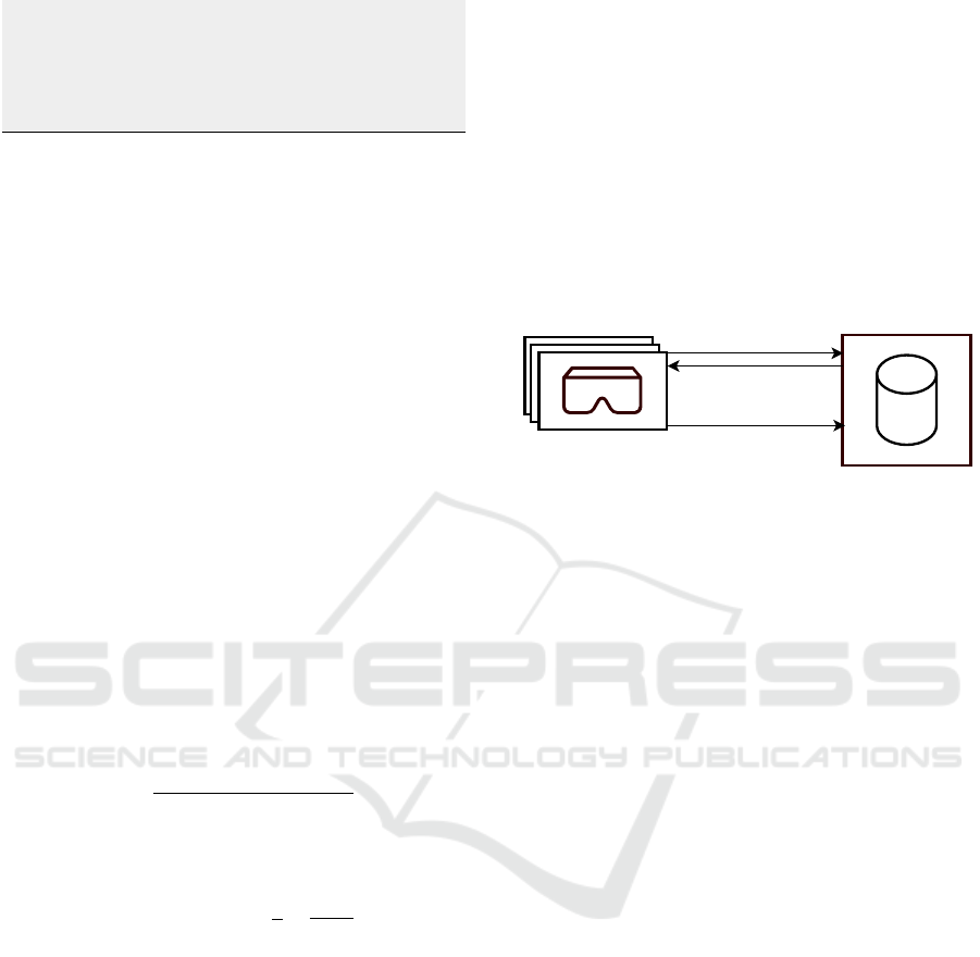
5 IMPLEMENTATION
The implementation of the proposed system is based
on a client-server architecture as shown in Figure
4, with a Python (Van Rossum and Drake Jr, 1995)
based server for persisting as well as exchanging geo-
referenced models using a RESTful (Fielding, 2000)
interface and multiple AR/MR clients utilizing these
models for occlusion purposes. These clients are cre-
ated with the Unity Game Engine for the Microsoft
HoloLens 2 as target platform. The basic concept of
creating geo-referenced models is independent of the
target platform in general, but is intended to import
and export occlusion models created with Microsoft’s
Mixed Reality Toolkit (Microsoft, 2021) and for this
requires a compatible device.
Clients
(Microsoft HoloLens 2)
Server Application
Geo-Referenced
GET-Request
GET-Response
(CityJSONs)
/linz?start=48.305,14.283&end=48.306,14.286
POST-Request
(CityJSON)
/linz
Figure 4: The proposed system architecture with multiple
clients based on the Microsoft HoloLens 2 and a server ap-
plication for exchanging geo-referenced models.
5.1 Client
The client application is based on the Unity Engine in
the version 2019.4.19f1. It is used to (I) request geo-
referenced models from the server application, (II) to
use those models for occlusion purposes, and to (III)
convert arbitrary Mesh objects to CityJSON represen-
tations, which are (IV) again forwarded to the server.
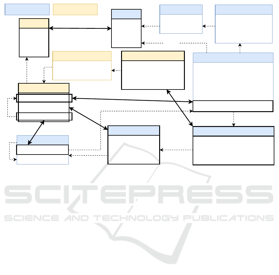
For this reason, CityJSON’s domain model has to be
converted to Unity’s object domain model and vice
versa. The mapping between these domain models
is shown in Figure 5, highlighting the related classes
and properties of both worlds. Based on this class di-
agram, the fundamental differences are visible, start-
ing with single floating point precision coordinates in
Unity’s Vector3, compared to the double-precision
based representation for geo-referenced coordinates
using Position. Single-floating point precision is
not sufficient for representing coordinates with sub-
meter accuracy within longitude, latitude and altitude
based systems as EPSG::4326 or WGS::84 (Reddy
et al., 2000). Note that CityJSON is not limited to
these coordinate reference systems, but this simplifi-
cation is used for the client side conversion process.
Among other differences, it has also to be stated that
Unity is limited to triangular polygons, represented
as a sequence of indices within the triangles prop-
erty of the Mesh class, while CityJSON supports any
type of polygon using its Face representation. This
characteristic requires an additional triangulation pro-
IVAPP 2022 - 13th International Conference on Information Visualization Theory and Applications
116

cess, when translating between both worlds. The con-
version of the two coordinate representations with
Vector3 and Position is shown in Listing 2.
Listing 2: The methods for converting between local and
global coordinates in pseudo code based on the methodol-
ogy presented in Section 4.
lo ca lD is t ( px , py , dx , dy ) {
x = p ow ( px - dx )
y = p ow ( py - dy )
re turn sq uare ( x + y ) / 63781 37
}
gl ob al Dist ( lat1 , lon1 , lat2 , l on2 ) {
a = si n2 (( la t2 - la t1 ) /2) +
cos ( lat1 ) * cos ( lat2 ) *
sin 2 (( lon2 - lon 1 ) / 2)
re turn 63 78 13 7 * 2 *
atan2 ( sq uare ( a ) ,
sq uare (1 - a ))
}
lo cal Be ar in g ( px , py , dx , dy , a ){
re turn atan2 ( py - dy , px - dx ) + a
}
gl oba lB ea rin g ( lat1 , lon1 , lat2 ,
lon2 , a ) {
re turn atan2 ( sin ( l on2 - l on1 ) *
cos ( lat2 ) , cos ( l at1 ) *
sin ( lat2 ) - sin ( lat1 ) *
cos ( lat2 ) *
cos ( lon2 - lon1 ) ) - a
}
di st an tLat ( lat1 , dist , bea ri ng ) {
re turn asi n ( si n ( lat1 )* cos ( di st ) +
cos ( lat1 ) * sin ( dist ) * cos (
be ar ing ) )
}
di st an tLon ( lat1 , lon1 , lat2 , dist ,
be ar ing ) {
re turn lon 1 + a tan 2 ( s in ( be ar ing ) *
sin ( lo cal _d is tan ce ) *
cos ( lat1 ) , cos ( d ist ) -
sin ( lat1 ) * sin ( lat2 ) )
}
Ve ct or3 toLoc al ( Vect or 3 start ,
Po si ti on referenc e , Po si ti on
toConvert , alp ha ){
d = gl ob alD is ta nce ( reference . lat ,
re fe re nc e . lng , t oC on ve rt . lat ,
to Co nv er t . lng )
b = gl ob alB ea ri ng ( r ef er en ce . lat ,
re fe re nc e . lng , t oC on ve rt . lat ,
to Co nv er t . lng , alpha )
re turn start + b * d
}
Po si ti on t oG lo ba l ( Vector 3 start ,
Po si ti on referenc e , Ve ctor3
toConvert , alp ha ) {
d = localDist ( st art .x , st art .y ,
to Co nv er t . x , t oC on ve rt . y )
b = lo ca lB ear in g ( start .x , sta rt .y ,
to Co nv er t . x , t oC on ve rt . y ,
alpha )
lat = di st an tL at ( r ef er en ce . lat , d )
lon = di st an tL on ( r ef er en ce . lat ,
re fe re nc e . lng , lat , d , b )
re turn Posi ti on ( lat , lon ,
to Co nv er t . z - start . z +
re fe re nc e . alt )
}
The proposed system is dedicated for occlusion
models and for this reason doesn’t consider textures.
Instead of that, Microsoft’s MRTK Occlusion ma-
terial is used. Although, the system can be used
for converting any Mesh object to a CityJSON rep-
resentation, it is primarily intended for exchang-
ing geo-referenced environmental models. To ac-
cess such a model in the context of Microsoft MR
devices, the IMixedRealityDataProviderAccess
service can be utilized to retrieve the mesh of the cur-
rent spatial environment. This mesh can be converted
with the proposed methodology to a CityJSON rep-
resentation, which in turn can be sent to the server
and like that exchanged with other system partic-
ipants. The IMixedRealityDataProviderAccess
service allows to access the environment model us-
ing one or multiple coherent meshes. These meshes
are separated based on a maximal number of vertices
and do not consider real world objects, thus parts of
an object may be part of the first mesh, while the re-
maining parts are in another mesh. Due to that, the se-
mantic meaning of a sub-mesh is hardly identifiable,
and so CityJSON’s GenericCityObject type should
be preferred in the conversion process, since it does
not limit the mesh to a specific semantic depiction. In
addition to that, there is also no information about the
level of detail (LoD) so the default value of 1 should
be used. To extract individual objects from the en-
vironment model, we propose a bounding box based
approach. Like this, a user can define the region of in-
terest, which allows filtering for suitable faces of the
environment’s mesh(es) and allows exchanging indi-
vidual sub-meshes.
Geo-Referenced Occlusion Models for Mixed Reality Applications using the Microsoft HoloLens
117
contains
contains
contains
contains
contains
contains
contains
CityJSON Domain Unity Domain
contains
related
related
related
related
CityJsonFile
+ type: string
+ version: string
+ metadata: MetaData
+ cityobjects: Map<string, CityObject>
+ vertices: List<Position>
Extent
+ start : Position
+ end : Position
Geometry
+ type: string
+ lod : int
+ boundaries : Face
Face
+ indices : List<int>
+ children : List<Face>
contains
related
contains
contains
Mesh
+ vertices: Vector3[]
...
+ triangles: int[]
references
references
Vector3
+ x : float
+ y : float
+ z : float
Position
+ lat: double
+ lng: double
+ alt: double
GameObject
- components : Component[]
+ name : string
...
MeshFilter : Component
+ mesh : Mesh
...
CityObject
+ name: string
+ type: string
+ geometries: List<Geometry>
Metadata
+ referencesystem : string
+ extent : Extent
+ lods : Map<string, int>
Figure 5: Domain model comparison between CityJSON and Unity in the context of representing object meshes, highlighting
the semantically related classes and properties.
5.2 Server
Next to the client application, we propose a server
implementation for (I) exchanging and (II) persisting
the created CityJSON models. Our reference imple-
mentation is based on Python 3.7.9 and utilizes two
main frameworks. On the one hand, we are using
PyProj (Pyproj4, 2014) in the version 3.1.0 for han-
dling and converting global coordinates, and on the
other hand Flask (Pallets, 2010) in the version 1.1.4
to realize the server’s RESTful interface. Based on
these frameworks, the server handles requests and
for this allows to exchange CityJSON model between
multiple devices and to manage multiple CityJSON
datasets. In the context of accessing models, the
server uses two parameters to identify suitable files.
First, it uses the dataset name to filter the resulting
objects. Since this type of filtering is not always in-
tended, a specialized “all” dataset can be used, which
ignores the dataset boundaries. Next to this parame-
ter, a start as well as an end coordinate should be pro-
vided to define the region of interest (ROI) in the form
of a bounding box. Based on this ROI the server again
allows to filter the files based on the geographical ex-
tent meta information within the individual CityJSON
files. In addition of filtering complete files, the end-
point also offers the possibility of a finer granularity
on the level of CityObjects and also on Face level.
These parameters are optional and allow to reduce the
amount of transmitted data. While filtering for com-
plete files or objects can be done without any risk, a
user has to consider that filtering for faces can dis-
member the objects and may result in shallow occlu-
sion models.
6 EVALUATION
The proposed methodology is evaluated based on a
bidirectional conversion functionality to translate a
given Unity Mesh object to a CityJsonFile object
and back to the Unity representation. After the con-
version, we are evaluating the error between the input
vertices to the corresponding output vertices. This is
done decoupled from the actual target MR platform
and from the server in order to be able to exclude pos-
sible additional external influences.
This quantitative evaluation is done using multi-
ple three-dimensional models in the form of OBJ files
and the EPSG::4326 coordinate (48.30285, 14.28428,
279.807) as reference point at the origin (0,0,0) of the
local coordinate system. These models are imported
to Unity, converted to a geo-referenced CityJSON
representation, and afterwards back-transformed to
Unity’s Mesh representation. Since the conversion
process preserves the ordering of individual vertices
IVAPP 2022 - 13th International Conference on Information Visualization Theory and Applications
118
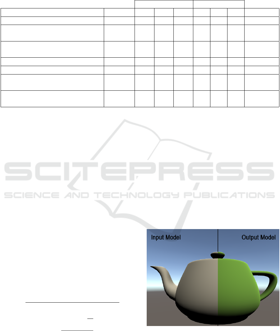
Table 1: Table showing the results of the quantitative evaluation with a minimal error of 1.30E-06 and a maximal one of
2.79E-04 based on the normalized sum of squared errors of the corresponding vertices between the conversion’s input and
output models.
Min Max
Object Vertices x y z x y z Error (m)
Cube 8 -0.5 -0.5 -0.5 0.5 0.5 0.5 2.79E-04
Stanford Bunny
(Turk and Levoy, 1994)
2503 -0.1 0.0 -0.1 0.1 0.2 0.1 1.30E-06
Utah Teapot
(Newell, 1975)
3241 -3.4 0.0 -2.0 3.0 3.2 2.0 3.49E-05
HoloLens Room Model 1 22805 -5.4 -1.9 -6.6 3.0 1.7 5.5 2.89E-05
HoloLens Room Model 2 67173 -4.2 -1.3 -4.5 6.0 1.6 8.8 1.87E-05
Stanford T-Rex
(Principia Inc., 1997)
100002 -0.8 -1.3 -2.1 0.8 1.3 2.1 3.90E-06
Stanford Armadillo
(Krishnamurthy and Levoy, 1996)
106289 -1.3 -1.1 -1.0 1.3 1.9 0.8 2.48E-06
of the mesh, the distances of every corresponding ver-
tex at index i with x
1
i, y
1
i and z
1
i of the input model
and the points of the back transformed mesh with x
2
i,
y
2
i and z
2
i can be used for the evaluation based on
the Pythagorean theorem as shown in Equation 8. We
are using the “sum of squared errors” metric, normal-
ized by the number of vertices, to describe model dif-
ferences based on the individual point distances, as
shown in Equation 9. The results are shown in Ta-
ble 1 with an error range from 1.30E-06 to 2.79E-04,
which can be interpreted as a quadratic offset between
the input and output model in meters, i.e. the error is
located in a sub millimeter range. This error can be
linked to two sources. On the one hand we are using
a spheric earth model, when converting between local
and global coordinates, with an approximated equa-
torial circumference of 6378137 meters and ignoring
ellipsoidal effects. This is ok for small objects, but the
error grows with the spatial expansion of the model.
On the other hand, while we are using a double pre-
cision for the global coordinates, Unity’s local coor-
dinate system is based on a floating point precision.
Because of this, the precision is lost, during the con-
version between the coordinate systems, which also
increases the error.
d
i
=
q
(x
2i
−x
1i
)
2
+ (y
2i
−y
1i
)
2
+ (z
2i
−z
1i
)
2
(8)
error =
∑
vertices
i=0
q
d
2
i
vertices
(9)
To visually highlight the influence of the conver-
sion error the input and the converted models are ex-
emplary compared in Figure 6. The shown model
is the Utah Teapot (Newell, 1975) from the previous
quantitative evaluation. This example shows, that the
minimal conversion errors as described in the quanti-
tative evaluation, are not recognizable by the human
eye, when using the system.
7 RELATED WORK
Keil et al. (2021) are utilizing geo-referenced CityJ-
SON models in combination with information from
OpenStreetMap to create three-dimensional scenarios
for Virtual Reality (VR) applications. To do so, the
models are once converted with the computer graph-
Figure 6: Visual comparison of the Utah Teapot (Newell,
1975) as input mesh model (left side), that is converted to
a CityJSON representation and back-transformed to a mesh
model (right side), showing that the minimal errors as de-
scribed in the quantitative evaluation are visually not recog-
nizable.
Geo-Referenced Occlusion Models for Mixed Reality Applications using the Microsoft HoloLens
119

ics software Blender and then imported into a Unity
application. In contrast to our work, the authors
are not transferring global coordinates to local ones
within their application during run time and don’t use
this approach for occlusion calculations. In addition
to that, they are not creating and sharing environmen-
tal models across devices, but only display existing
data sets.
Buyukdemircioglu and Kocaman (2020) present a
system for visualizing existing urban structures in
combination with future planned buildings based on
CityGML representations and VR devices. The aim
of the system is the virtual exploration of the fu-
ture city model and like this deviates from our work,
where we are focusing on dynamically creating and
sharing environmental models in the context of AR
applications.
Blut and Blankenbach (2020) describe a
smartphone-based system in the context of civil
engineering utilizing CityGML models based
on a previously published mobile CityGML AR
viewer (Blut et al., 2019). The system is intended
for geo-referenced on-site visualization of planned
buildings and is focusing on visually estimating a
user’s pose within the given model by comparing
real-world objects with their digital representations.
Compared to this work, we are not estimating the
pose of the user and are using CityGML, respectively
CityJSON only as source for object occlusion and
information sharing.
Chalumattu et al. (2020) present an approach for
sharing location-based, virtual objects in the context
of outdoor AR applications. To do so, the authors
use a static city model, that is linked with Microsoft’s
Spatial Anchor system and additional visual markers
for Android devices to real world positions. Based on
this basic model and the spatial reference information,
a user can place additional virtual objects, which can
be shared with other participants. The shared objects
are occluded based on the city model. In contrast to
our work, Chalumattu et al. don’t share dynamically
created occlusion models of the user’s environment,
and also don’t incorporate world coordinates.
Multiple publications (Kilimann et al., 2019;
Capece et al., 2016; Ghadirian and Bishop, 2008)
present the utilization of geographic information sys-
tems (GIS) in the context of outdoor AR applications.
The introduced methodologies are used to place vir-
tual counterparts at given global positions, retrieved
from such services. In contrast to our work, the
authors don’t exchange concrete 3D geometries, but
only position and type information and are placing
statically pre-defined models based on this input. In
addition to that, the authors focus on sharing objects
for the visualization of e.g. changes in the local vege-
tation or infrastructural points of interest as electrical
power lines instead of dynamically, created occlusion
models. Due to the utilization of GIS, the approaches
of the before mentioned publications are dependent
on the up-to-dateness of the shared information like
torn down or new constructed buildings in urban sce-
narios.
8 CONCLUSION
The utilization of the CityJSON format for exchang-
ing spatial information in the context of occlusion
models shows promise. The results show that dy-
namically created geo-referenced three-dimensional
geometries can be successfully exchanged over mul-
tiple AR and MR devices in the context of outdoor
scenarios and occlusion models.
As the accuracy of the placed objects’ position
is dependent on one reference point, it is only as
good as the system providing this information. Which
means, that sharing occlusion models across multi-
ple devices, will only result in accurately covered
objects, when all participants have exact knowledge
about their global position. On basis of the server side
filtering methods, the system allows sharing occlusion
models within a spatial restricted region of interest,
leading to a reduced data volume when accessing the
information. Like this, state-of-the-art MR devices
such as the Microsoft HoloLens 2 can exchange up-
to-date environmental information, also with limited
network bandwidths.
9 OUTLOOK
Due to the promising results of sharing geo-
referenced occlusion models across multiple Mi-
crosoft HoloLens 2 devices, we plan to also incor-
porate models from different sources as e.g. cam-
era based 3D reconstructions from smartphones or
drones. This extension will allow us increasing the
size of the available dataset, as well as supported de-
vices, with the aim of improving the occlusion possi-
bilities in outdoor scenarios. Especially, in the area of
task force training, this step will allow us creating dy-
namic training scenarios by integrating not fixed po-
sitioned objects such as boxes or barrels. In addition,
we also plan to partially reduce the dependency to the
global reference position by correcting positional er-
rors based on the comparison of visual features and
the used models.
IVAPP 2022 - 13th International Conference on Information Visualization Theory and Applications
120

ACKNOWLEDGMENT
Our thanks to the Austrian Research Promotion
Agency FFG for facilitating the project MRCC with
the Small Scale Project funding program (program
number: 883742), with research budget provided by
the Federal Republic of Austria. The authors also
thank their project partners of the Austrian Mixed Re-
ality company Realsim
®
, especially Thomas Peterseil,
Erik Thiele and Mario Voithofer, for the close coop-
eration and their efforts.
REFERENCES
Blut, C., Blut, T., and Blankenbach, J. (2019). Citygml
goes mobile: application of large 3d citygml mod-
els on smartphones. International Journal of Digital
Earth, 12(1):25–42.
Bray, T. et al. (2014). The javascript object notation (json)
data interchange format.
Bray, T., Paoli, J., Sperberg-McQueen, C. M., Maler, E.,
Yergeau, F., and Cowan, J. (2000). Extensible markup
language (xml) 1.0.
Capece, N., Agatiello, R., and Erra, U. (2016). A client-
server framework for the design of geo-location based
augmented reality applications. In 2016 20th Inter-
national Conference Information Visualisation (IV),
pages 130–135.
Chen, J. X. (2003). 3d file formats. In Guide to Graphics
Software Tools, pages 127–136. Springer New York,
New York, NY.
De Crescenzio, F., Fantini, M., Persiani, F., Di Stefano,
L., Azzari, P., and Salti, S. (2011). Augmented re-
ality for aircraft maintenance training and operations
support. IEEE Computer Graphics and Applications,
31(1):96–101.
Fielding, R. T. (2000). Architectural styles and the design
of network-based software architectures. University
of California, Irvine.
Gavish, N., Guti
´
errez, T., Webel, S., Rodr
´
ıguez, J., Peveri,
M., Bockholt, U., and Tecchia, F. (2015). Evaluating
virtual reality and augmented reality training for in-
dustrial maintenance and assembly tasks. Interactive
Learning Environments, 23(6):778–798.
Ghadirian, P. and Bishop, I. D. (2008). Integration of aug-
mented reality and gis: A new approach to realistic
landscape visualisation. Landscape and Urban Plan-
ning, 86(3):226–232.
Gr
¨
oger, G. and Pl
¨
umer, L. (2012). Citygml–interoperable
semantic 3d city models. ISPRS Journal of Pho-
togrammetry and Remote Sensing, 71:12–33.
Haas, J. (2014). A history of the unity game engine. Diss.
WORCESTER POLYTECHNIC INSTITUTE.
Haleem, A., Javaid, M., Goyal, A., and Khanam, T. (2020).
Redesign of car body by reverse engineering tech-
nique using steinbichler 3d scanner and projet 3d
printer. Journal of Industrial Integration and Man-
agement, page 2050007.
Heinz, E., Eling, C., Wieland, M., Klingbeil, L., and
Kuhlmann, H. (2015). Development, calibration and
evaluation of a portable and direct georeferenced laser
scanning system for kinematic 3d mapping. Journal
of Applied Geodesy, 9(4):227–243.
H
¨
ubner, P., Clintworth, K., Liu, Q., Weinmann, M., and
Wursthorn, S. (2020). Evaluation of hololens tracking
and depth sensing for indoor mapping applications.
Sensors, 20(4):1021.
Ingrassia, P. L., Mormando, G., Giudici, E., Strada, F.,
Carfagna, F., Lamberti, F., and Bottino, A. (2020).
Augmented reality learning environment for basic life
support and defibrillation training: Usability study.
Journal of Medical Internet Research, 22(5):e14910.
Izadi, S., Kim, D., Hilliges, O., Molyneaux, D., Newcombe,
R., Kohli, P., Shotton, J., Hodges, S., Freeman, D.,
Davison, A., et al. (2011). Kinectfusion: real-time 3d
reconstruction and interaction using a moving depth
camera. In Proceedings of the 24th annual ACM sym-
posium on User interface software and technology,
pages 559–568.
Javaid, M., Haleem, A., Pratap Singh, R., and Suman, R.
(2021). Industrial perspectives of 3d scanning: Fea-
tures, roles and it’s analytical applications. Sensors
International, 2:100114.
Kaplan, A. D., Cruit, J., Endsley, M., Beers, S. M., Sawyer,
B. D., and Hancock, P. (2020). The effects of virtual
reality, augmented reality, and mixed reality as train-
ing enhancement methods: a meta-analysis. Human
factors, page 0018720820904229.
Kaplan, E. D. and Hegarty, C. (2017). Understanding GP-
S/GNSS: principles and applications. Artech house.
Khronos Group Inc. (2008). Collada overview - the khronos
group inc. https://www.khronos.org/collada/. (Ac-
cessed on 07/22/2021).
Kilimann, J.-E., Heitkamp, D., and Lensing, P. (2019). An
augmented reality application for mobile visualiza-
tion of gis-referenced landscape planning projects. In
The 17th International Conference on Virtual-Reality
Continuum and its Applications in Industry, pages 1–
5.
Kingsland, K. (2020). Comparative analysis of digital pho-
togrammetry software for cultural heritage. Digital
Applications in Archaeology and Cultural Heritage,
18:e00157.
Krishnamurthy, V. and Levoy, M. (1996). Fitting smooth
surfaces to dense polygon meshes. In Fujii, J., ed-
itor, Proceedings of the 23rd Annual Conference on
Computer Graphics and Interactive Techniques, SIG-
GRAPH 1996, New Orleans, LA, USA, August 4-9,
1996, pages 313–324. ACM.
Ledoux, H., Ohori, K. A., Kumar, K., Dukai, B., Labetski,
A., and Vitalis, S. (2019a). Cityjson: A compact and
easy-to-use encoding of the citygml data model. Open
Geospatial Data, Software and Standards, 4(1):1–12.
Ledoux, H., Ohori, K. A., Kumar, K., Dukai, B., Labet-
ski, A., and Vitalis, S. (2019b). Datasets — cityj-
Geo-Referenced Occlusion Models for Mixed Reality Applications using the Microsoft HoloLens
121

son. https://www.cityjson.org/datasets/. (Accessed on
08/03/2021).
McKnight, R. R., Pean, C. A., Buck, J. S., Hwang, J. S.,
Hsu, J. R., and Pierrie, S. N. (2020). Virtual reality
and augmented reality—translating surgical training
into surgical technique. Current Reviews in Muscu-
loskeletal Medicine, pages 1–12.
Microsoft (2021). microsoft/mixedrealitytoolkit-
unity: Mixed reality toolkit (mrtk) provides a
set of components and features to accelerate
cross-platform mr app development in unity.
https://github.com/microsoft/MixedRealityToolkit-
Unity. (Accessed on 08/03/2021).
Newell, M. (1975). Utah teapot.
https://graphics.stanford.edu/courses/cs148-10-
summer/as3/code/as3/teapot.obj. (Accessed on
08/05/2021).
Nguyen, T.-N., Huynh, H.-H., and Meunier, J. (2018). 3d
reconstruction with time-of-flight depth camera and
multiple mirrors. IEEE Access, 6:38106–38114.
Nolan, D. and Lang, D. T. (2014). Keyhole markup lan-
guage. In XML and Web Technologies for Data Sci-
ences with R, pages 581–618. Springer.
Pallets (2010). pallets/flask: The python mi-
cro framework for building web applications.
https://github.com/pallets/flask/. (Accessed on
08/06/2021).
Portele, C. (2007). Opengis® geography markup language
(gml) encoding standard. version 3.2. 1. OGC Stan-
dards.
Praschl, C., Krauss, O., and Zwettler, G. A. (2020). En-
abling outdoor mr capabilities for head mounted dis-
plays: a case study. International Journal of Simula-
tion and Process Modelling, 15(6):512–523.
Principia Inc. (1997). Stanford t-rex.
https://www.prinmath.com/csci5229/OBJ/index
.html. (Accessed on 08/05/2021).
Pyproj4 (2014). pyproj4/pyproj: Python interface to proj
(cartographic projections and coordinate transforma-
tions library). https://github.com/pyproj4/pyproj. (Ac-
cessed on 08/06/2021).
Reddy, M., Iverson, L., and Leclerc, Y. G. (2000). Un-
der the hood of geovrml 1.0. In Proceedings of the
fifth symposium on Virtual reality modeling language
(Web3D-VRML), pages 23–28.
Swaminathan, A. (2019). Perception at magic leap. Georgia
Tech Seminars.
Tachella, J., Altmann, Y., Mellado, N., McCarthy, A., To-
bin, R., Buller, G. S., Tourneret, J.-Y., and McLaugh-
lin, S. (2019). Real-time 3d reconstruction from
single-photon lidar data using plug-and-play point
cloud denoisers. Nature communications, 10(1):1–6.
Taketomi, T., Uchiyama, H., and Ikeda, S. (2017). Visual
slam algorithms: a survey from 2010 to 2016. IPSJ
Transactions on Computer Vision and Applications,
9(1):1–11.
Thøgersen, M., Andoh, J., Milde, C., Graven-Nielsen, T.,
Flor, H., and Petrini, L. (2020). Individualized aug-
mented reality training reduces phantom pain and cor-
tical reorganization in amputees: A proof of concept
study. The Journal of Pain, 21(11):1257–1269.
Turk, G. and Levoy, M. (1994). Stanford bunny.
https://graphics.stanford.edu/ mdfisher/Data/Mesh-
es/bunny.obj. (Accessed on 08/05/2021).
Turner, A. and Coulter, D. (2019). Spatial an-
chors - mixed reality — microsoft docs.
https://docs.microsoft.com/en-us/windows/mixed-
reality/design/spatial-anchors. (Accessed on
07/21/2021).
Ungureanu, D., Bogo, F., Galliani, S., Sama, P., Duan, X.,
Meekhof, C., St
¨
uhmer, J., Cashman, T. J., Tekin, B.,
Sch
¨
onberger, J. L., et al. (2020). Hololens 2 research
mode as a tool for computer vision research. arXiv
preprint arXiv:2008.11239.
Van Rossum, G. and Drake Jr, F. L. (1995). Python refer-
ence manual. Centrum voor Wiskunde en Informatica
Amsterdam.
Van Schaik, J. (2017). Using a hololens scanned room
inside your hololens app - dotnetbyexample - the
next generation. https://localjoost.github.io/using-
hololens-scanned-room-inside-your/. (Accessed on
07/22/2021).
Veness, C. (2019). Calculate distance and bearing be-
tween two latitude/longitude points using haversine
formula in javascript. https://www.movable-
type.co.uk/scripts/latlong.html. (Accessed on
08/03/2021).
Vergel, R. S., Tena, P. M., Yrurzum, S. C., and Cruz-
Neira, C. (2020). A comparative evaluation of a vir-
tual reality table and a hololens-based augmented re-
ality system for anatomy training. IEEE Transactions
on Human-Machine Systems, 50(4):337–348.
Westerfield, G., Mitrovic, A., and Billinghurst, M. (2014).
Intelligent augmented reality training for motherboard
assembly. International Journal of Artificial Intelli-
gence in Education, 25(1):157–172.
Wu, Y. (2021). Application research of terrain mapping
based on riegl 3d scanning system. In IOP Confer-
ence Series: Earth and Environmental Science, vol-
ume 719, page 042058. IOP Publishing.
Zunke, S. and D’Souza, V. (2014). Json vs xml: A compar-
ative performance analysis of data exchange formats.
IJCSN International Journal of Computer Science and
Network, 3(4):257–261.
IVAPP 2022 - 13th International Conference on Information Visualization Theory and Applications
122
