
Experimental Investigation of a Novel Dual-mode Power Split System
for Passenger Vehicle
Wei Du, Shengdun Zhao
*
, Liying Jin, Yangfeng Cao, Jinzhou Gao and Hao Li
School of Mechanical Engineering, Xi’an Jiaotong University, Xi’an 710049, China
904416827@qq.com, wojiaolihao114@stu.xjtu.edu.cn
Keywords: Hybrid electric vehicle, Power split, Planetary gear, Input-split, Compound-split.
Abstract: Hybrid systems are becoming ever more widely used because they can improve the fuel economy of
automobiles. This paper proposes a new hybrid system based on the three row planetary gear train, which can
switch between input-split and compound-split mode according to different road conditions. This paper
introduces its structure and operating mode, and uses the 1.8L displacement Toyota Prius as an example.
According to its design parameters, a prototype is designed and a control strategy based on logic threshold is
established. The operating characteristics of the system were analyzed through a bench test. The experimental
results show that compared with the 1.8L Toyota Prius power train, the novel dual-mode power split hybrid
power train system can reduce fuel consumption by 11.4%.
1 INTRODUCTION
In the next 50 years, the world population will grow
from 6 billion to 7 billion, and car ownership will
increase from 700 million to 2.5 billion (chan, 2001).
If all these cars continue to use engines, the
consequent environmental pollution problems will be
unimaginable (chan, 2002), and these factors force us
to rapidly develop alternative energy-driven
automotive technology. At present, hybrid
technology is one effective way to improve fuel
consumption and reduce emissions.
According to the definition, the hybrid electric
vehicle needs to have two power sources of engine
and electric motor, and can achieve high energy
utilization rate through efficient and precise control
system, which makes it have low fuel consumption,
low emission and excellent advantages such as
dynamic performance (Ehsani, 2007; Lin, 2003;
Sciarretta, 2007 ; Pisu, 2007). According to the
connection form of the internal combustion engine
with the motor and the transmission, the hybrid
electric vehicle can be divided into three types: a
series hybrid vehicle (SHEV), a parallel hybrid
vehicle (PHEV) and a series-parallel hybrid vehicle
(SPHEV) (Meisel, 2006).
In the first generation of the Prius, Toyota
creatively proposed the use of a planetary gear power-
split system for hybrid vehicle (Meisel, 2011). The
system consists mainly of an engine, a planetary gear
train and two motors. Using the planetary gear train
as a power coupling device, the decoupling of the
engine rotating speed and torque can be realized by
two motors and a planetary gear train with two
degrees of freedom, and the power of the engine is
divided into two parts: electric power and mechanical
power. However, the power-split mode of this
configuration is relatively simple, and it is not
possible to switch modes to adapt to different road
conditions (Miller, 2006 ; Liu, 2008).
The dual-mode hybrid system is a hot research
problem in the field of hybrid technology because it
has two power-split modes and can improve fuel
economy in a wider range of transmission ratios. This
paper proposes a novel dual-mode hybrid system. The
Prius was used as an example to design a prototype.
The control strategy based on the logic threshold was
used to test the performance of the system. The
experimental results show that the fuel economy of
the novel dual-mode hybrid system is improved
compared with the Toyota Prius powertrain.
108
Du, W., Zhao, S., Jin, L., Cao, Y., Gao, J. and Li, H.
Experimental Investigation of a Novel Dual-mode Power Split System for Passenger Vehicle.
DOI: 10.5220/0011359000003355
In Proceedings of the 1st International Joint Conference on Energy and Environmental Engineering (CoEEE 2021), pages 108-114
ISBN: 978-989-758-599-9
Copyright
c
2022 by SCITEPRESS – Science and Technology Publications, Lda. All rights reserved
2 DESCRIPTION OF THE
SYSTEM STRUCTURE AND
OPERATING MODE
The novel dual-mode hybrid system proposed in this
paper has two power-split modes: input-split and
compound-split. The system works in the compound-
split mode in the middle and low gear ratio range, and
works in the input-split mode in the high gear ratio
range. The mode is switched by the control of the
clutches.
The configuration of the novel dual-mode power-
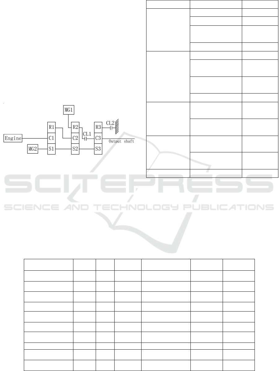
split hybrid system proposed in this paper is shown in
figure 1. The parameters of different parts of the
system are shown in table 1.
Figure 1: Configuration of the novel dual-mode power-split
hybrid system.
Table 1. System parameters.
Component Parameter Value
Vehicle
Weight/kg
1467.4
Wheelbase/mm
2700
Wind resistance
coefficient
0.29
Tire radius/m
0.282
Engine
model
5ZR-FXE
Maximum
power/kW
73
Maximum
torque/Nm
142
Displacement/L
1.8
MG1
MG1 rated
power/kW
30
MG1 rated
speed/rpm
3000
MG2
MG2 rated
power/kW
33
MG2 rated
speed/rpm
3000
Battery
capacity/kWh
1.3
The system has two types of power-split modes:
input-split and compound-split. The corresponding
vehicles have reverse gear, low speed running,
medium and high speed running, rapid acceleration,
braking and other working conditions. The control
system selects different operating modes based on the
power demand signal from the driver, the current
vehicle speed, the battery SOC value, and the current
operating state of the engine and the motors.
According to the working state of the engine, MG1,
MG2 and the engagement or disengagement of the
CL1 and CL2, the system has a total of 10 operating
modes, as showed in table 2.
Table 2: The operating modes of the system.
Operating mode Engine MG1 MG2 Engine and system CL1 CL2
Reverse gear stop stop run disconnected disengaged engaged
Single motor drive stop stop run disconnected disengaged engaged
Dual motor drive stop run run disconnected engaged disengaged
Engine cold start follow run stop connected disengaged engaged
Engine hot start follow run run connected disengaged engaged
Charge run run run /stop connected disengaged engaged
Input-split run run Run connected disengaged engaged
Compoun
d
-split run run run connecte
d
engage
d
disengage
d
Mild brake stop stop run disconnected disengaged engaged
Heavy braking stop run run disconnected engaged disengaged
Experimental Investigation of a Novel Dual-mode Power Split System for Passenger Vehicle
109

3 CONTROL STRATEGY
Control strategies of existing power-split hybrid
vehicle mainly include logic threshold-based control
strategies, genetic algorithm based control strategies,
fuzzy rule based control strategies, and adaptive
dynamic control strategies (Salmasi, 2007; Sciarretta,
2007). In order to make it easier to be compared and
analyze the experimental results, this paper chooses
the control strategy based on logic threshold. The
control strategy based on the logic threshold is
essentially to map all the states that the vehicle may
encounter during driving to different operating modes
of the hybrid system, and at the same time, set the
discriminating conditions and thresholds for the
transition between different modes. For the novel
dual-mode power-split hybrid system proposed in this
paper, there is a total of 10 effective operating modes
as showed in table 2. The control strategy based on
the logic threshold needs to select the corresponding
operating modes according to the set rules and
determine the power distribution of the engine and the
two motors.
The mode switching rules based on the logic
threshold are as follows: The target operating point
and the permissible working range of the engine are
set according to the efficient operating range of the
engine. Set the battery SOC value working range to
ensure its performance and extend its service life.
According to the current gear position information
and torque demand collected by the sensors,
combined with the battery SOC value, select the
operating mode of the system. The heavy braking
energy recovery mode or the mild braking energy
recovery mode is selected according to the vehicle
speed and the battery SOC. The threshold values of
the main parameters are set as follows.
3.1 Battery SOC Value
The SOC (state of charge) value of expresss the
power level of battery, which is usually represented
by a number between 0 and 1. In the process of using
the hybrid vehicle,as to prolong the service time of
battery, it is necessary to shallowly charge it.
Therefore, in the control strategy based on the logic
threshold, the upper limit SOCmax=0.8 and the lower
limit SOCmin=0.4 are respectively set. In any pattern,
if the current SOC of battery is <SOCmin, the engine
is started and enters the charging mode or the hybrid
driving mode. When the vehicle needs to decelerate
braking, according to the real-time SOC of battery,
the proportion of electric brake participation during
braking is determined; when SOC>SOCmax, the full
hydraulic braking mode is adopted.
3.2 Vehicle Speed Threshold V_ref
Both the engine and the MG1 and MG2 have their
maximum speed limits, and each has a speed range
corresponding to the efficient working area.
Therefore, different speed thresholds need to be set so
that the vehicle always runs in the most suitable mode
while driving. Set the vehicle speed threshold
v_ref1=30km/h, v_ref2=60km/h. The engine is
inefficient at idle speed. Therefore, when SOC value
of the battery is greater than its lower limit value, the
engine only run when the vehicle speed is greater than
the threshold value v_ref1. When the vehicle speed is
lower than v_ref1, it operates in pure electric mode.
The input-split mode is suitable for low speed.
Therefore, when the vehicle speed is in the range of
(v_ref1, v_ref2), the input-split pattern is
preferentially chosen; if the vehicle speed is greater
than v_ref2, switch to compound-split mode.
3.3 Demand Torque T_req Threshold
When designing and optimizing a hybrid system, not
only its fuel economy but also the dynamic
performance of the vehicle must be met. The real-
time torque required during vehicle travel is derived
from the opening of the throttle and brake pedals and
represents the instantaneous power demand. The
control strategy of this paper linearly converts the
signal of the accelerator pedal opening and the
demand torque, and assigns it to the engine and two
motors with the goal of fuel economy. While the
engine, MG1 and MG2 have their upper limit of
output torque and the optimal output torque range, so
we should set the threshold for the demand torque as
the evaluation standard for mode switching.
First,it is judged that it is currently in the drive
mode, the parking mode or the braking mode
according to 𝑇_𝑟𝑒𝑞 > 0, 𝑇_𝑟𝑒𝑞 = 0,or T_req<0. In
the drive pattern: if the battery SOC>SOCmin, the
vehicle speed v<30km/h, the vehicle runs in pure
electric drive mode. When 𝑇_𝑟𝑒𝑞 < 30𝑁𝑚, a single
motor drive, when T_req>30Nm, double motor drive.
When the instantaneous torque demand T_req>90
Nm, the engine starts to work and provides torque.
When T_req=0 and the duration is greater than 3s, the
vehicle enters the parking or coasting mode. At this
time, if the battery SOC value is greater than the
lower limit threshold, the engine stops. In the braking
mode, the mechanical brake, single motor auxiliary
electric brake or dual motor auxiliary electric brake
CoEEE 2021 - International Joint Conference on Energy and Environmental Engineering
110
mode is selected rely on the vehicle speed and battery
SOC value.
3.4 Validation Test
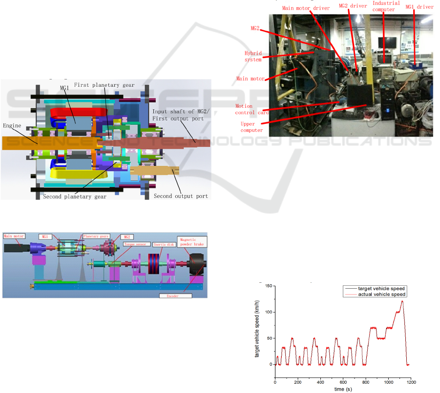
Figure 2 is the model of the novel dual-mode power-
split hybrid system, including MG1, three-row
planetary gear train, engine input shaft and MG2
motor input shaft. In order to simplify the structure,
the MG1 rotor is designed as a hollow structure,
directly connected to the ring gear of the second
planetary gear train. Considering the experimental
verification of the hybrid system, the two clutches
showed in figure 1 need to be equipped with hydraulic
or electronic control units separately, which is
difficult and costly. At the same time, the structure of
the three sets of planetary rows is too complicated.
Therefore, in the structural design and subsequent
experimental research, the structure consisting of two
sets of planetary rows with dual output ports is used,
and the reduction ratio of the third row of planetary
transmissions is realized by the sprocket. During
system testing, the current operating mode can be
selected as input-split or compound-split through
different output port.
Figure 2: The 3D model of the novel dual-mode power-split
hybrid system.
Figure 3: The model of the hybrid system test bench.
In order to test the speed and torque of each
component of the hybrid system under different
working modes and to test the fuel economy of the
system, the experimental platform of the hybrid
system is built according to figure 3. The physical
diagram is shown in figure 4. It includes a main motor
for simulating the engine, an experimental device, a
torque sensor for testing the output speed and torque
signal, an adjustable inertia disk for simulating the
vehicle's driving inertia, and a magnetic powder
brake. The hybrid system includes a flux switching
permanent motor(FSPM) as MG1,a permanent
magnet synchronous motor(PMSM) as MG2, and a
power split device composed of two rows of planetary
gear trains that are connected to the subsequent test
unit through a sprocket of the first or the second
output port. The control system mainly consists of
three servo motor drivers, two upper computers and
one motion control card. The upper computer
connected to the control card sends the speed and
torque control commands to the servo motor driver by
means of the motion control card, and reads the
current and speed signals collected by the driver. The
industrial computer is used to control the magnetic
powder brake, and read the speed and torque signals
measured by the torque sensor.
Figure 4: Hybrid system test bench.
In order to verify the performance of the novel
dual-mode power-split hybrid system, the fuel
economy experiment was carried out on the system.
The fuel economy experiment was carried out under
the NEDC cycle condition (Wang, 2013).The target
and actual vehicle speed in the experimental process
are shown in figure 5. It can be seen from the figure
that the presence of the motor effectively improves
the acceleration and deceleration performance of the
hybrid system, so the actual vehicle speed and the
target speed basically coincide.
Figure 5: Comparison of target speed and actual speed.
Experimental Investigation of a Novel Dual-mode Power Split System for Passenger Vehicle
111
(a)
(b)
(c)
Figure 6: The speed, torque and power of the engine:(a)
variation of engine speed with time;(b) variation of engine
torque with time;(c) variation of engine power with time.
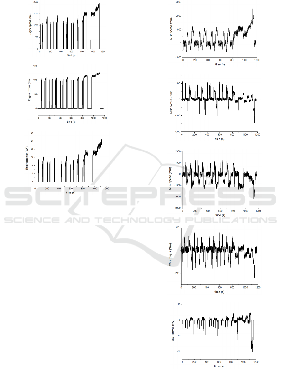
The engine speed, torque and power during the
experiment is shown in figure 6. As we can see from
figure 6(a), since there are two motors in the hybrid
system, the vehicle is mainly driven by the motor at
low speed. Under normal urban conditions, the engine
does not work most of the time, and only starts
charging the battery when the battery SOC value is
low.
In order to analyze the performance of the two
motors, the curves of the speed and torque of the two
motors are obtained during the experiment. As is
shown in figure 7, in low speed case (less than
30km/h), MG1 does not work and torque of it is 0
Nm. In this case, MG2 is used as the drive motor. In
the case of medium speed, when the battery SOC is
greater than 0.4, MG1 and MG2 drive the vehicle
together. When the battery SOC is less than 0.4, the
engine is started. At this time, the engine speed and
torque are adjusted by MG1 and MG2, so that the
engine always works in high efficiency.
(a)
(b)
(c)
(d)
(e)
CoEEE 2021 - International Joint Conference on Energy and Environmental Engineering
112
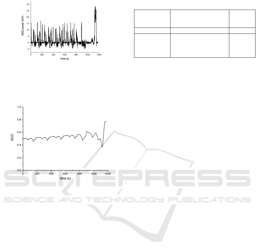
(f)
Figure 7: The speed, torque and power of two motors:
(a)variation of MG1 speed with time; (b) variation of MG1
torque with time; (c) variation of MG2 speed with time; (d)
variation of MG2 torque with time; (e) variation of MG1
power with time; (f) variation of MG1 power with time.
Figure 8: The SOC value of battery.
Limited by the experimental conditions, the
battery is replaced by a simulation model. According
to the measured power of the engine, MG1, and MG2,
theoretical SOC of the battery can be calculated, and
the variation curve is shown in figure 8. In pure
electric mode, the energy of the motor is provided by
the battery, the SOC value decreases, and when the
vehicle speed increases, the system is in the engine
drive mode. If the SOC value is lower at this time,
part of the energy of the engine is used to drive the
car, and the other part is used to charge the battery to
increase the SOC of the battery. When the system is
in a braking state, braking energy is recovered by
MG1 and MG2 and stored in the battery.
In order to evaluate the fuel economy of the
proposed novel dual-mode power-split hybrid
system, the equivalent fuel consumption of the Prius
hybrid system and the novel dual-mode power-split
hybrid system is compared under the same driving
cycle. As showed in table 3, the novel dual-mode
power-split hybrid system can save fuel consumption
by 11.4% compared to the Prius hybrid system. It can
be seen that the novel dual-mode power-split hybrid
system can effectively improve fuel economy.
Table 3. Comparison of fuel consumption rate.
Fuel
consumption(L/100km)
Energy
saving
rate
Prius 4.3
Novel dual-
mode power-
split hybrid
system
3.81 11.4%
5 CONCLUSION
This paper proposes a novel dual-mode power-split
hybrid system based on a three-row planetary gear
train, which is mainly composed of an engine, a three-
row planetary gear train and two motors. After
analyzing the configuration and operating mode of
the system, taking the Toyota Prius as an example, a
prototype was made and a bench test was carried out.
The experimental results show that the fuel economy
of the novel dual-mode power-split hybrid system is
11.4% higher than the Toyota Prius. It can be seen
that the novel dual-mode power-split hybrid system is
a good hybrid solution.
ACKNOWLEDGMENTS
This work was jointly supported by the Fundamental
Research Funds for the National Key Research and
Development Program of China (Grant
No.2017YFD0700200) and the National Natural
Science Foundation of China for key Program (Grant
No. 51335009).
REFERENCES
Chan C, Chau K. (2001). Modern Electric Vehicle
Technology[J]. Power Engineer, 16(5):240-240.
Chan C C. (2002). The state of the art of electric and hybrid
vehicles[J]. Proceedings of the IEEE, 90(2):247-275.
M. Ehsani, Y. Gao, and J. Miller. (2007). “Hybrid electric
vehicles: Architecture and motor drives,” Proc. IEEE,
vol. 95, no. 4, pp. 719–728.
C. C. Lin, H. Peng, J. W. Grizzle, and J. Kang. (2003).
“Power management strategy for a parallel hybrid
electric truck,” IEEE Trans. Control Syst.Technol., vol.
11, no. 6, pp. 839–849.
A. Sciarretta and L. Guzzella. (2007). “Control of hybrid
electric vehicles,” IEEE Control. Syst. Mag., vol. 27,
no. 2, pp. 60–70.
P. Pisu and G. Rizzoni. (2007). “A comparative study of
supervisory control strategies for hybrid electric
Experimental Investigation of a Novel Dual-mode Power Split System for Passenger Vehicle
113

vehicles,” IEEE Trans. Control Syst. Technol., vol. 15,
no. 3, pp. 506–518.
Meisel J. (2006). An Analytic Foundation for the Toyota
Prius THS-II Powertrain with a Comparison to a Strong
Parallel Hybrid-Electric Powertrain[C]// SAE 2006
World Congress & Exhibition.
Meisel J. (2011). Kinematic Study of the GM Front-Wheel
Drive Two-Mode Transmission and the Toyota Hybrid
System THS-II Transmission[J]. Sae International
Journal of Engines, 4(1):1020-1034.
Miller, J.M. (2006). Hybrid electric vehicle propulsion
system architectures of the e-CVT type. IEEE Trans.
Power Electron. 21, 756–767.
Liu, J.; Peng, H. (2008). Modeling and control of a power-
split hybrid vehicle. IEEE Trans. Control Syst. Technol.
16, 1242–1251.
Salmasi, F.R. (2007). Control strategies for hybrid electric
vehicles: Evolution, classification, comparison, and
future trends. IEEE Trans. Veh. Technol. 56, 2393–
2404.
Sciarretta, A.; Guzzella, L. (2007). 2007 Control of hybrid
electric vehicles. IEEE Control Syst. 27, 60–70.
J. Wang, X. Yuan, and K. Atallah. (2013). 2013 Design
optimization of a surfacemounted permanent-
magnetmotor with concentrated windings for electric
vehicle applications, IEEE Trans. Veh. Technol., vol.
62, no. 3, pp. 1053–1064.
CoEEE 2021 - International Joint Conference on Energy and Environmental Engineering
114
