
An Improved Device for the Calibration of Nerve and Muscle
Stimulator
Yang Xu
1a
, Tingting Ren
2b
, Ying Liu
3c
, Yanxiang Fu
4d
and Huijuan Wang
1e
1
Center for Medical Metrology, Chongqing Academy of Metrology and Quality Inspection, Chongqing, China
2
Center for Length Metrology, Chongqing Academy of Metrology and Quality Inspection, Chongqing, China
3
Center for Chemistry and Environmental Metrology, Chongqing Academy of Metrology and Quality Inspection,
Chongqing, China
4
Center for Mechanics Metrology, Chongqing Academy of Metrology and Quality Inspection, Chongqing, China
Keywords: Nerve and Muscles Stimulator, RMS Value of Output Current, Stimulating Signal Frequency, DC
Component, RMS Value of Interference Current, Pulse Duration, Channel Stability, Treatment Time Error,
Calibration Device.
Abstract: Nerve and muscle stimulator is widely used in medical institutions for the diagnosis and/or therapy of
neuromuscular disorders. This article presents a novel design of calibration test device for the calibration of
nerve and muscle stimulator, and studies the essential parameters of the equipment such as "RMS value of
output current", "stimulating signal frequency", " DC component ", "RMS value of interference current",
"pulse duration", "channel stability" and “treatment time error” in order to present a feasible procedure for the
periodic calibration of nerve and muscle stimulator and to establish the metrological traceability system of
the instrument. The calibration result shows that the calibration test device and the calibration procedure
presented in this article can ensure the metrological traceability of nerve and muscle stimulator.
1 INTRODUCTION
Nerve and muscles stimulator is medical electrical
equipment for the application of electric currents via
electrodes in direct contact with patient for the
diagnosis and/or therapy of neuromuscular disorders.
It can provide low and/or intermediate frequency
pulse electrical stimulation for the treatment of
headache, paralysis, renal calculus, sciatica and
angina pectoris. Its working principle is to generate a
variety of different output signals according to the
needs of diagnosis and treatment purposes. The
electrodes are patched to the patient’s skin to
stimulate the rhythmic contraction of nerves and
muscles, so as to delay the atrophy of diseased
muscles and help the compensatory proliferation of
muscle fibers, which will promote the function
recovery of nerve excitation and conduction. Nerve
and muscle stimulator is wildly used in China,
a
https://orcid.org/0000-0001-8385-9790
b
https://orcid.org/0000-0002-6320-0179
c
https://orcid.org/0000-0001-8244-1034
however, applicable national metrological
verification regulation of which has not been issued
so far, and the corresponding traceability system of
which has not been established yet.
The purpose of this paper is to study the
influencing factors on essential technical parameter
such as "RMS value of output current", "stimulating
signal frequency", " DC component ", "RMS value of
interference current", "pulse duration", "channel
stability" and “treatment time error” of nerve and
muscle stimulator, so as to design a novel calibration
device and to establish an applicable calibration
procedure, in order to improve medical treatment
quality, which will ultimately benefit the patients’
health and guard their safety.
d
https://orcid.org/0000-0001-5289-274X
e
https://orcid.org/0000-0001-6633-6453
Xu, Y., Ren, T., Liu, Y., Fu, Y. and Wang, H.
An Improved Device for the Calibration of Nerve and Muscle Stimulator.
DOI: 10.5220/0011184700003444
In Proceedings of the 2nd Conference on Artificial Intelligence and Healthcare (CAIH 2021), pages 69-74
ISBN: 978-989-758-594-4
Copyright
c
2022 by SCITEPRESS – Science and Technology Publications, Lda. All rights reserved
69
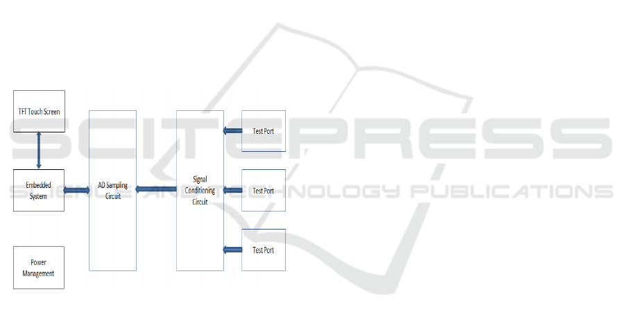
2 DESIGN OF CALIBRATION
DEVICE FOR NERVE AND
MUSCLE STIMULATOR
The calibration device for nerve and muscle
stimulator is mainly composed of channel selection
part, signal conditioning part, high-speed AD
sampling analysis part, power management part and
operating system. The channel selection part selects
one or more different channels to be tested through
CPU control, and adjusts the signal through the
resistance attenuation network and PGA (digital
controllable gain amplifier) of the signal conditioning
part to adapt to AD sampling. The CPU collects the
measured signal through its own high speed signal
sampling channel, obtains the amplitude frequency
parameters of the signal through FFT (fast Fourier
transform), and ultimately gets all the parameters
needed through other algorithms, which will all be
displayed on TFT LCD for reading. The power
management section manages all power supplies of
the device. The system diagram of the calibration
device is demonstrated in Figure 1:
Figure 1: System Diagram of the Calibration Device for
nerve and Muscle Stimulator.
2.1 Channel Selection Part
The device can test three input channels respectively,
and can also test two or three superimposed signals at
the same time, which is realized by CPU controlling
relay network. The relay network is composed of self-
locking relays, and the advantage of which is low
power consumption for the control current only needs
to be applied when the switch pulls in the channel and
there is no need to maintain the current after, which
reduces the power consumption of the whole device.
After channels are determined, channel impedance
can be selected according to the test requirements.
2.2 Signal Conditioning Part
Since the test range of the designed input signal is up
to ± 700V, the input signal must be attenuated to meet
the maximum input range of the system circuit
elements. The attenuation network adopts resistance
attenuation, which attenuates the signal about 148
times.
In order to ensure the measurement accuracy of
the small signal, the system uses PGA (digital
controllable gain amplifier) 280 to amplify the small
signal and improve the accuracy of AD sampling.
PGA280 is a zero drift, HV programmable gain
amplifier. Its excellent electrical characteristics
ensure the stability of the signal measured by the
system.
2.3 High Speed AD Sampling Analysis
The main control unit and high-speed AD sampling
of the system adopt SMT32F407VET6.
SMT32F407VET6 is a microprocessor with
ARMCortex-M4 core specially designed by ST
Microelectronics based on embedded applications
requiring high performance, low cost and low power
consumption. The core contains ARM
®
32-bit cortex
®
- M4CPU of FPU, adaptive real-time accelerator
(ART accelerator
TM
) for realizing no-wait state
operation performance, and MPU with DPS
instruction set for realizing the performance of 210
DMIPS/1.25DMIPS/MHz (Dhrystone 2.1). The
memory is consisted of Flash of up to 1MB and
SRAM of up to 192 + 4 KB including 64-KB CCM
(kernel coupled memory) data RAM and flexible
external storage controllers with up to 32-bit data bus:
SRAM, PSRAM, NOR / NAND memory.
2.4 Power Management Part
The device adopts a single lithium-ion battery to
provide power supply. The power supply voltage of
the digital part of the system is 3.3V, the power
supply voltage of the LCD backlight and relay is 5V,
and the voltage of the analog (PGA) part is ± 5V.
Power supply circuit of digital part: the power
supply of digital part is generated by step-down DC /
DC chip TPS62260 manufactured by TI. This chip is
an efficient DC / DC step-down chip with output
current up to 600mA, switching frequency up to
2.25MHz, input voltage of (2-6)V, and static power
consumption as low as 15μA. Its 100% duty cycle can
provide electricity when the battery voltage is low to
the output voltage, further improving the utilization
of the battery.
CAIH 2021 - Conference on Artificial Intelligence and Healthcare
70
LCD backlight and relay power supply circuit: the
power supply of this part is generated by step-up DC
/ DC chip TPS61040 manufactured by TI. This chip
is an efficient DC / DC step-up chip with an output
current of 400mA, a switching frequency of 1MHz,
an input voltage of (2-6) V, an output voltage of up to
28V and a static power consumption of 28μA.
Analog (PGA) power supply circuit: the power
supply of this part provides analog voltage for PGA,
and its power performance directly affects the
performance index of the whole system, therefore,
higher requirements of this part is necessary. The
power supply of this part is generated by dual output
DC / DC chip TPS65133 manufactured by TI. The
output voltage of the chip is fixed at ± 5V, with the
accuracy of 1%. The output current of the chip from
positive to negative direction is up to 250mA, with
excellent line and load transient response. The power
supply circuit operates in continuous conduction
mode (CCM) to supply noise-free output voltage.
2.5 Operating System
μC / OS II (Micro Control Operation System Two) is
a scalable, preemptive, real-time multitasking kernel
that can run based on ROM. it has high portability,
especially suitable for microprocessors and
controllers. It is a real-time operating system (RTOS)
with the same performance as many business
operating systems. μC / OS II can be roughly divided
into five parts: core, task processing, time processing,
task synchronization & communication, and CPU
transplantation.
1) Core (OSCore. c) is the processing core of the
operating system, including operating system
initialization, operating system operation, leading in
and out of interrupts, clock beat, task scheduling,
event processing and so on. It’s the part that maintains
the basic work of the whole system.
2) Task Processing (OSTask. c) is closely related
to the operation of the task, including task creation,
deletion, suspension, recovery, etc. μC / OS II
dispatches basic unit of task, therefore, this part is
also very important.
c) Clock (OSTime. C) μ The minimum clock unit
in μC / OS II is timetick. Task delay and other
operations are completed here.
d) Task synchronization & communication part is
the event processing part, including semaphore,
mailbox, message queue, event flag, etc. It is mainly
used for the interconnection between tasks and access
to critical resources.
e) The interface with CPU refers to the porting
part of used CPU of μC / OS-II. As a universal
operating system, implementation of key issues still
needs to be transplanted into μC / OS-II according to
the specific contents and requirements of specific
CPU. This part is usually written in assembly
language because it involves system pointers such as
SP. It mainly includes the bottom implementation of
interrupt level task switching, the bottom
implementation of task level task switching, the
generation and processing of clock beat, the related
processing of interrupt and so on.
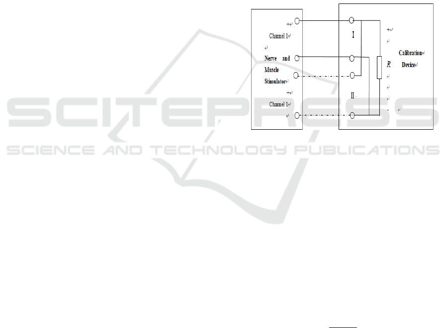
3 CALIBRATION PROCEDURE
Connect the calibration device presented in Chapter 2
with a nerve and muscle stimulator according to
Figure 2:
Figure 2: Schematic Diagram of Calibration for Nerve and
Muscle Stimulator.
3.1 Error of Output Current RMS
Value
Set the impedance of the calibration device to 500 Ω
and the voltage to 700V, select a channel of the
stimulator, adjust the output power of the stimulator
to the maximum value, observe the output signal
waveform, and record the maximum current RMS
value measured by the calibration device after the
signal waveform is stable. The error of output current
RMS value of the stimulator is calculated according
to equation (1):
△I =
%100
0
0
×
−
I
II
(1)
I——Maximum nominal RMS current of nerve
and muscle stimulator, mA;
△ I——Error of Maximum nominal RMS
current;
I
0
——Maximum nominal RMS current measured
by calibration device, mA.
An Improved Device for the Calibration of Nerve and Muscle Stimulator
71

3.2 Stimulating Signal Frequency
Error
Set the impedance of the calibration device to 500 Ω
and the voltage to 700V, adjust the output power of
the stimulator to the half of the maximum value,
observe the output signal waveform, and record the
frequency measured by the calibration device after
the signal waveform is stable. The error of
stimulating signal frequency of the stimulator is
calculated according to equation (2):
△f =
%100
0
0
×
−
f
ff
(2)
f——Nominal stimulating signal frequency of
nerve and muscle stimulator, Hz;
△f——Stimulating signal frequency error;
f
0
——Stimulating signal frequency value
measured by calibration device, Hz.
3.3 DC Component Error
Set the impedance of the calibration device to 500 Ω
(or 2000Ω when the calibrated nerve and muscle
stimulator is applied in Ophthalmic or dental
diagnosis) and the voltage to 700V, adjust the output
power of the stimulator to the maximum value,
observe the output signal waveform, and record the
DC component measured by the calibration device
after the signal waveform is stable. The DC
component error of the stimulator is calculated
according to equation (3):
△I
D
=
%100
0
0
×
−
D
DD
I
II
(3)
D
I
——Nominal DC component of nerve and
muscle stimulator, mA;
△I
D
——DC component error;
0
D
I
——DC component value measured by
calibration device, mA.
3.4 Pulse Duration Error
Set the impedance of the calibration device to 1000 Ω
and the voltage to 700V, select the commonly used
output signal of the nerve and muscle stimulator, and
the electrical stimulation mode channel of the
calibration device, adjust the output power of the
stimulator to the half of the maximum value, observe
the output signal waveform, and record the pulse
duration measured by the calibration device after the
signal waveform is stable. The pulse duration error of
the stimulator is calculated according to equation (4):
△T =
%100
0
0
×
−
T
TT
(4)
T
——Nominal pulse duration of nerve and
muscle stimulator, μs;
△T——Pulse duration error;
0
T
——Pulse duration value measured by
calibration device, μs.
3.5 Treatment Time Error
Select the nominal timing value (5min or 10min) of
the nerve and muscle stimulator, and measure the
actual stimulation treatment time with a stopwatch.
The time error is calculated according to equation (5):
△t =
%100
0
0
×
−
t
tt
(5)
t ——Nominal treatment time of nerve and
muscle stimulator, min;
△t——Treatment time error;
0
t
——Treatment time measured by calibration
device, min.
3.6 RMS Value of Interference
Current
For stimulators with two or more stimulation
channels, it is necessary to measure the interference
current of the stimulator. Select two or three
measured signals with similar frequencies of the
nerve and muscle stimulator, set the impedance of the
calibration device to 500 Ω and the voltage to 700V,
adjust the power output of the stimulator to the
maximum value, observe the output signal waveform,
and record the RMS value of the interference current
measured by the calibration device after the signal
waveform is stable.
3.7 Channel Stability
Set the impedance of the calibration device to 1000 Ω
and the voltage to 700V, select the commonly used
output signal of the nerve and muscle stimulator, and
the electrical stimulation mode channel of the
calibration device, adjust the output power of the
stimulator to the half of the maximum value, observe
the output signal waveform, and record the maximum
and minimum RMS current values under the same
frequency measured by the calibration device within
CAIH 2021 - Conference on Artificial Intelligence and Healthcare
72
30min after the signal waveform is stable. The pulse
duration error of the stimulator is calculated
according to equation (6):
%100
2
minmax
×
−
=
I
II
γ
(6)
max
I
——Maximum RMS value of output
current, mA;
min
I
——Minimum RMS value of output current,
mA;
I
——Average RMS value of output current,
mA;
γ
——Channel stability
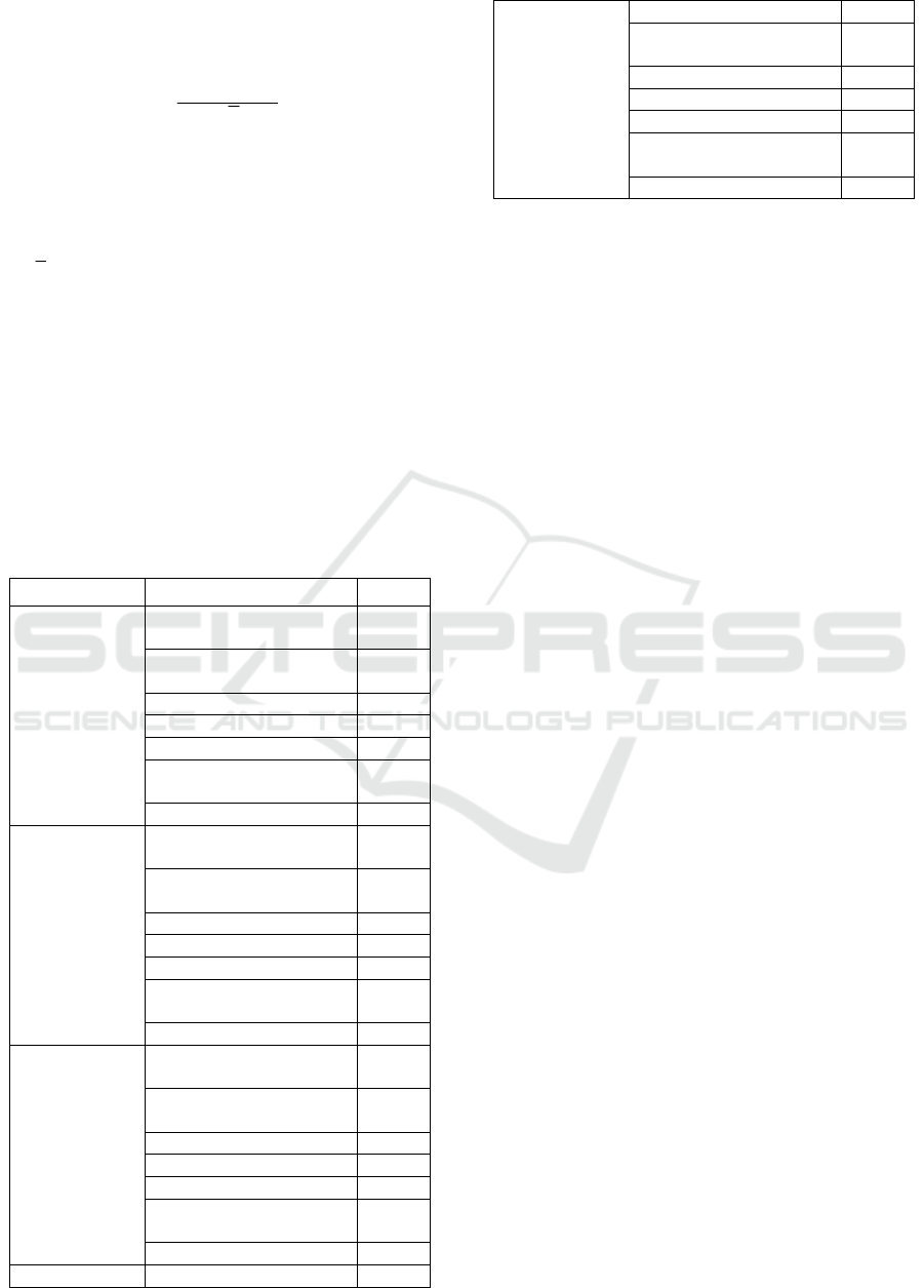
4 CALIBRATION RESULT
Select several typical types of nerve and muscle
stimulators as the calibrated subjects. The
experimental result is demonstrated in Table 1:
Table 1: Calibration Results.
Type Parameter Result
XY-K-SISS-K
Error of Output Current
RMS Value
3.9%
Stimulating Signal
Frequency Erro
r
8.7%
DC Com
p
onent Erro
r
2.8%
Pulse Duration Erro
r
3.1%
Treatment Time Erro
r
1.3%
RMS Value of
Interference Current
70mA
Channel Stabilit
y
2.0%
KT-90A
Error of Output Current
RMS Value
9.9%
Stimulating Signal
Frequency Erro
r
4.2%
DC Component Erro
r
6.8%
Pulse Duration Erro
r
1.0%
Treatment Time Erro
r
1.3%
RMS Value of
Interference Current
64mA
Channel Stabilit
y
1.9%
PHENIXUSB4
Error of Output Current
RMS Value
6.4%
Stimulating Signal
Fre
q
uenc
y
Erro
r
0.0%
DC Component Erro
r
5.9%
Pulse Duration Erro
r
-2.0%
Treatment Time Erro
r
-5.3%
RMS Value of
Interference Current
5.0mA
Channel Stability 1.7%
KWD-808I Error of Out
p
ut Current 3.1%
RMS Value
Stimulating Signal
Fre
q
uenc
y
Erro
r
0.0%
DC Com
p
onent Erro
r
6.8%
Pulse Duration Erro
r
1.0%
Treatment Time Erro
r
-3.3%
RMS Value of
Interference Current
4.5mA
Channel Stability 0.4%
The calibration results have met the metrological
criterion set by YY 9706.210-2021 Test method for
measuring output characteristics of nerve and muscle
stimulators and the enterprise standards of the
calibrated subjects.
5 CONCLUSIONS
The article studies the key technical parameters such
as "RMS value of output current", "stimulating signal
frequency", " DC component ", "RMS value of
interference current", "pulse duration", "channel
stability" and “treatment time error” of nerve and
muscle stimulator, designs the appropriate calibration
device for the measurement of the parameters, and
presents the novel calibration procedure for the
equipment, and the feasibility of which has been
proved by the calibration results.
Therefore, the article presents a feasible
procedure for the periodic calibration of nerve and
muscle stimulator in order to establish the
metrological traceability system of the instrument.
Further work is worth to be done to improve the
calibration method of infant phototherapy incubator.
ACKNOWLEDGEMENTS
Our work was supported by the Science Research
Project of AQSIQ (Grant No. 2015QK184).
REFERENCES
IEC 60601-2-10 (2016) Medical electrical equipment-Part
2-10: Particular requirements for the basic safety and
essential performance of nerve and muscle stimulator.
International Electrotechnical Commission, Geneva.
Vrbová, G., Hudlicka, O. and Schaefer Centofanti, K.:
Electrical stimulation as a therapeutic tool to restore
motor function, in: Vrbová, G., Hudlicka, O. and
Schaefer Centofanti, K.: Application of Muscle/Nerve
An Improved Device for the Calibration of Nerve and Muscle Stimulator
73

Stimulation in Health and Disease, Springer,
Heidelberg, pp. 55-67, 2008.
Ward, A.R.: Biophysical Bases of Electrotherapy,
Butterworth-Heinemann, Oxford, 2006.
YANG Y., et al.. Research on detection of output
characteristics of nerve and muscle stimulators[J].
Medical Equipment, 2016(02):19-22
YY 0696(2021) Test method for measuring output
characteristics of nerve and muscle stimulators.
National Medical Products Administration, Beijing.
YY 9706.210(2021) Particular requirements for the basic
safety and essential performance of nerve and muscle
stimulators. National Medical Products Administration,
Beijing.
CAIH 2021 - Conference on Artificial Intelligence and Healthcare
74
