
Modelling and Simulation of Battery Charger Li-Ion using
CC-CV PI Method
Munir Rifa’i, Novie Ayub Windarko
and Farid Dwi Murdianto
Electrical Engineering Department, Politeknik Negeri Elektronika Surabaya, Surabaya, Indonesia
Keywords: Battery Charger, Buck Converter, Charging, Constant Current, Constant Voltage, PI Controller, Voltage
Threshold.
Abstract:
Damage to the battery is caused by improper and correct charging methods. So it is necessary to have a
system to maintain battery life time. The method is often used to charge batteries is constant voltage by
providing a constant voltage from initial charging to full charge. Charging with constant voltage can provide
a high charging current at the beginning of charging. High charging currents can be dangerous and reduce
battery lifetime. In this seminar paper, charging Li-Ion batteries using Buck Converter with constant current
constant voltage method, namely by providing a constant current before reaching the voltage threshold and
continuing with a constant voltage to full (charging current 3-5% of the capacity of the battery). PI control is
used in the Buck Converter which serves to maintain the stability of the current (constant current) and the
voltage (constant voltage) by output buck converter. With this method the initial current when charging can
be limited according to the ability of the battery, so that more current does not occur and the battery lifetime
will be longer. The PI control on the buck converter can produce a constant current and a constant voltage at
a battery load, with a current ripple of 12.5% and steady state 4A at a constant current and a voltage ripple
of 0.95% and steady state 42V at a constant voltage.
1
INTRODUCTION
In this globalization era, many electrical devices
use
batteries as their energy source. The electrical
devices
in question are like laptops, unmanned aircraft
(UAVs),
even electric vehicles use batteries as their
energy
source. Means of transportation that are
currently
returning to the trend are bicycles, because it
functions
as a means of recreation, sports and short
distance
transportation. Seeing this, an electric bicycle
was
developed as a hybrid vehicle that uses human
power
and an electric motor. This vehicle has a number
of
advantages, including less energy than using human-
powered vehicles, does not consume fuel, does not
cause pollution, is not noisy, low maintenance costs,
does not require special permission to drive and does
not require a large parking area. A battery is a device
that can store electricity. The types of batteries
circulating in the community are as follows Lead Acid,
Ni-CD, Li-Ion, and Li-Po. Overall the batteries
mentioned above, the Li-Ion battery is one of the most
widely used, because Li-Ion batteries have many
advantages such as, large capacity with small
physical size, no memory effect and can supply high
currents up to 20 times its capacity (Thowil and
Ayu, 2015). After the battery is used, it will cause
the battery to decrease
its capacity, to be able to
return to its maximum
capacity the battery must be
charged first. There are
several methods for charging
a battery, one of the
methods is Constant Current
Constant Voltage (CC-
CV), this method is suitable
for Li-Ion batteries
because the age of a Li-Ion
battery is greatly
influenced by overcharging
conditions so that using
this method can extend the
battery's life (Vu and Tran, 2018).
To be able to process the battery charging in
Constant Current Constant Voltage can use Buck
Converter. It is because the buck converter has a
voltage and current output with a small riple (Surya
and Zuhri, 2017). So
it is suitable for use in the
battery charging process.
PI controller is used in
Buck Converter section
which serves to maintain the
stability of the output
current (Constant Current)
and the output voltage
(Constant Voltage) of the
Buck Converter. The
stability of the current released
until the battery
voltage capacity reaches the
voltage threshold.
Furthermore, the stability of the
issued voltage to
full battery capacity with the
current parameter is cut
off.
Rifa’i, M., Windarko, N. and Murdianto, F.
Modelling and Simulation of Battery Charger Li-Ion using CC-CV PI Method.
DOI: 10.5220/0010968000003260
In Proceedings of the 4th International Conference on Applied Science and Technology on Engineer ing Science (iCAST-ES 2021), pages 1501-1506
ISBN: 978-989-758-615-6; ISSN: 2975-8246
Copyright
c
2023 by SCITEPRESS – Science and Technology Publications, Lda. Under CC license (CC BY-NC-ND 4.0)
1501
2
DESIGN OVERALL SYSTEM
2.1 Battery Charger System
The battery is an electric cell in which an
electrochemical process takes place that can be
reversed so that
in the battery there are two
processes namely the discharge process occurs when
the conversion of
chemical energy into electrical
energy while the
charging process occurs when the
conversion of
electrical energy into chemical energy.
The charging
process can occur by means of
regeneration of the
electrodes in it by providing an
electric current in the
opposite direction in the cell
(Rashid, 2011) and (Ashari, 2017).
Constant Current Constant Voltage, which is to
the battery voltage reaches its maximum voltage
then
it is continued with Constant Voltage until the
current decreases according to the cut-off current.
By using this method the battery charging will be in
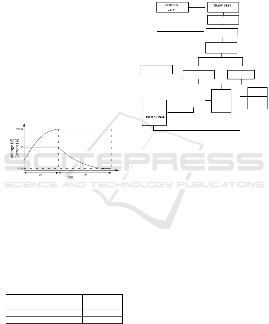
Figure 1: Charging of constant current constant voltage.
Figure 4 above shows the process of charging a
battery using the Constant Current Constant Voltage
method. Charging starts with Constant Current and
continues with Constant Voltage until the battery
capacity is fully charged.
Lithium-Ion batteries used in this paper have a
total of 10 series and 3 parallel cells. The battery
charging process is done simultaneously. The
capacity of the Li-Ion battery used is 10.5 Ah. As for
the design of the Li-Ion battery charger can be seen
in table 2. Where for constant current is set at 4 A
current and for constant voltage is set at 42V.
Table 1: Specification of battery charger.
Parameters Value
Constant Current 4 A
Constant Voltage 42 V
Total Cells 10S 3P
a)
Block Diagram System
Block diagram system of battery charger is
shown in
Figure 2.
Figure 2: Block diagram system of battery charger.
Figure 5 explains that the source for this battery
charger uses 220 VAC / 50 Hz PLN electricity, which
will be reduced using a step-down transformer of
220VAC to 48 VAC. Next will be rectified into a DC
voltage (Direct Current) using the Fullwave
Uncontrolled Rectifier to 67.8 VDC. The output
voltage of the rectifier will be varied using Buck
Converter. The voltage sensor and current sensor are
used to read the voltage and
current
from the battery
which will then be
compared to the value of the
setpoint. The result will be an error signal which will
then be processed by Arduino and produce a PWM
control signal. Then the PWM signal will be
strengthened in the mosfet driver so that the mosfet
can switch.
B) The Flowchart of Constant Current Constant
Voltage (CC-CV)
The flowchart battery charger system of constant
current constant voltage shown in Fig. 3.
DOWN
RECTIFIER
BUCK
KONVERTER
SENSOR
SENSOR
VOLTAGE
SETPOINT
STM32F4
PI
KONTROLLER
-
-
+
LI-Ion
BATERRY
CURRENT
+
SETPOINT
iCAST-ES 2021 - International Conference on Applied Science and Technology on Engineering Science
1502
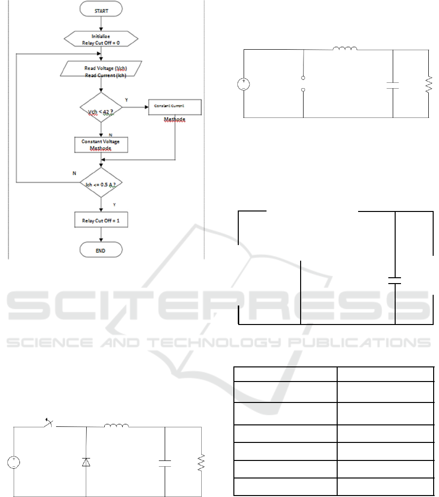
Figure 3: Flowchart system CC-CV.
2.2 Buck Converter
Functions to reduce voltage. The working principle
of the Buck Converter is to use a switch that works
continuously (ON-OFF). As for the so-called PWM
(Pulse Width Modulation) and Duty Cycle in
controlling the speed (frequency) work of the
switch. The choice of buck converter is based on
high efficiency in changing input power to output
power (Pulungan and Sukardi, 2018) and (Wahyu and
Supriono, 2018).
Figure 4: Equivalent of buck converter circuit.
The rating of inductors and capacitors can be
found by following equation (Hart, 2011):
Vo χ (1-D) (1)
Δ iL χf
ΔV =Vo 0.1% (2)
1 - D 8Lrf 2 (3)
Then the switch is in the ON position, diode reverse
bias. Here the inductor starts to absorb some
of the
power from the power supply (Hart, 2011).
Figure 5: Buck converter is ON condition.
When the switch is at the OFF point. Although
not
connected to the source, at this position the
power is
supplied from the inductor which has
absorbed
power as long as the circuit is connected to
the source
(switch position ON).
Figure 6: Buck converter is OFF condition.
Table 2: buck converter parameters.
2.3 PI Controller
Proportional control functions to strengthen the error
signal of the driver (error signal), so that it will speed
up the system output to the reference point. Integral
Control in principle aims to eliminate the error of
steady state (offset) which is usually generated by
proportional control (Suryatini). However, the use of
P controller alone cannot eliminate the steady state
L
S
Vin D C
L
S
VIn
D C
Parameters Value
Input Voltage (Vs) 65 V
Output Voltage (Vo) 42 V
Output Current (Io)
4 A
Switching Frekuensi (fs)
100 kHz
Ripple Current(∆iL)
20%
Ripple Voltage (r)
0.1%
L
Vin
D
Modelling and Simulation of Battery Charger Li-Ion using CC-CV PI Method
1503
error, therefore a PI controller is needed to eliminate
the steady state error. The use of this PI controller can
also reduce rise time and settling time. Just like the P
controller, increasing the Ki value to a certain value
will also increase the overshoot value
(Temel).
Set
Point
E Controlled
ror
Measured
Sensor
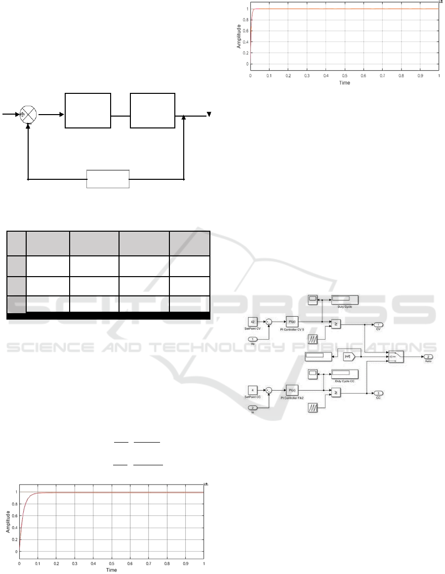
Figure 7: Block diagram of PI controller system.
Table 3: Characteristic of pid controller.
Rise Time
Settling Time
Error Steady
State
Overshoot
p
Decrease Small Change Decrease Increase
i
Decrease Increase Eliminate Increase
d
Small Change Decrease Small Change Decrease
The PI controller that is used in the system is
obtained from the simulation response of the buck
converter which uses the predetermined parameters
(Marian, 2012).
The open-loop transfer function
(OLTF) of the system is shown in equation (4) and the
response of the OLTF
shown in Figure 8 and the closed-
loop transfer function
(CLTF) of the system is shown in
equation (5) and the
response of the CLTF shown in
Figure 9.
F= OLT
.
.
(4)
F= CLT
.
(5)
Figure 8: Step response of Open-Loop Transfer Function
(OLTF).
Figure 9: Step response of Close-Loop Transfer Function
(CLTF).
3
SIMULATION RESULT
Battery charging simulation is done using two modes,
namely constant current and constant voltage modes. The
constant current mode works first by giving a constant
current until the charging voltage
reaches its maximum
value. After the voltage reaches
its maximum value, it
is continued with a constant
voltage mode, which is to
provide a constant voltage
until the current flowing
in the battery reaches its
cut-off value.
PI controller is used to optimize the output
voltage and current to be stable in the setpoint. The
simulation uses Matlab with certain patterns.
Figure 10: PI Controller and switch constant current to
constant voltage.
The simulation results for the battery charging
system using constant current constant voltage are
shown in Figure 11.
4 CONCLUSION
The technical and economic analysis of tracker
based solar power system for remoted islanded has
been presented. The potential of the energy of the
PV system can be generated 3,341 kWh/year. The
test result using three different PV structure
installations - fixed structures, single-axis tracking,
and dual-axis tracking mechanisms, shows that the
Kp +
Ki/s
Buck
Converter
Output
iCAST-ES 2021 - International Conference on Applied Science and Technology on Engineering Science
1504

two-axis tracking system has more profitable in
terms of PV electricity production 3,931 kWh in a
year and had the lowest COE of 0,307 $/kWh. This
system requires less PV module and battery storage,
as well as lowest PV system, cost 2,579 $, and less
space needed for system installation. The analysis of
environmental influence needs to be considered for
future research in order to reduce CO
2
emission.
Figure 11: Simulation result of constant current (CC)
constant voltage (CV) from: (a) output voltage
response,
(b) output current response.
The controller adjusts the duty cycle value
assigned
to the buck converter to match the setpoint.
PI
controller can reach the setpoint value with a time
of
0.004s and maintain the charging current
according
to the setpoint. The constant current setpoint is 4A
and the constant voltage setpoint is
42V.
From Table 4, the simulation results of
battery charging using the constant current constant
voltage method, the percentage of charging current
error at CC is obtained by 0.5%. The constant
current (CC) charging process takes place up to 99%
battery SOC. After that, the charging process
switches to CV mode until SOC is 100%. The
simulation is performed with a discrete signal
(sample times is 1e-6) and starting at the 99% SOC
battery condition with a matlab time of 20.
Table 4: Simulation results.
SO
C (%)
Vb
Open (V)
V
ch
(
V)
ch
(A)
(Ω)
30 36.915
37.3 3. 0.11
76 95 67
35 36.930
37.3 4. 0.11
98 00 67
40 36.943
37.4 4. 0.11
12 02 67
45 36.953
37.4 4. 0.11
20 00 67
50 36.962
37.4 4. 0.11
28 00 67
55 36.971
37.4 4. 0.11
38 00 67
60 36.982
37.4 4. 0.11
50 02 67
65 36.999
37.4 3. 0.11
64 99 67
70 37.030
37.4 3. 0.11
97 99 67
75 37.092
37.5 4. 0.11
60 00 67
80 37.224
37.6 4. 0.11
93 02 67
85 37.505
37.9 4. 0.11
72 00 67
90 38.109
38.5 4. 0.11
77 01 67
95 39.415
39.8 3. 0.11
83 99 67
96 39.820
40.2 3. 0.11
87 99 67
97 40.292
40.7 4. 0.11
60 00 67
98 40.844
41.3 4. 0.11
11 00 67
99 41.487
41.9 4. 0.11
55 00 67
99.235 41.532
42.0 3. 0.11
00 00 67
99.5 41.768 42.00 1.97 0.1167
99.6 41.94 42 0.5 0.1167
Table 5: Switching results.
SOC
S
tart
at
Switch
CC to CV
Setpoint
Output
Mean
Oscillation
99 %
at SOC
Current 4 A 4.022 A 12.5 %
99.1438
%
Voltage 42 V 42.014 V 0.95 %
Table 5 shows the process of switching from
constant current (CC) to constant voltage (CV). The
displacement occurs when the SOC of the battery is
99.14% with a charging voltage (Vch) of 42 V and a
charging current (Ich) of 0.5 A. The allowed
charging voltage of the battery is 42 V (according to
the datasheet). With a CC current of 4 A, it lasts
until the charging voltage is 42 V. So that's when the
CC switches to CV. The oscillations that occur
Modelling and Simulation of Battery Charger Li-Ion using CC-CV PI Method
1505

against the current setpoint are 12.5% and the
oscillations that occur against the voltage setpoint are
± 0.95%. Oscillation can be affected by the buck
voltage source (rectifier), PI control value and
switching frequency.
Figure 12: The simulation results of a full battery cut off.
Fig. 12, shows the charging process is
complete (full). The battery will be considered full
when the charging voltage is 42 V and the charging
current drops to <= 0.5 A. The cut off process occurs
when the SOC of the battery in the simulation is
99.6%. Battery voltage when open circuit after
charging process is 41.94 V.
REFERENCES
M. Ashari. (2017). desain konverter elektronika daya.
Informatika Bandung.
F Suryatini, A Firasanti. Journal of Electrical and
Electronics (JREC) P, PI, And PID Control Ii Settings
DC Motor Speed With ZIEGLER-NICHOLS Tuning.
Vol 6 No 1.
D. W. Hart. (2011). Power Electronics New York:
McGraw-Hill.
M. Thowil Afif dan I. Ayu Putri Pratiwi. (2015).
Analisis Perbandingan Baterai Lithium-Ion, Lithium-
Polymer, Lead Acid dan Nickel-Metal
Hydride pada
Penggunaan Mobil Listrik – Review. Jurnal Rekayasa
Mesin, vol. 6, no. 2, hlm. 95–99.
V.-B. Vu, D.-H. Tran, dan W. Choi. (2018).
Implementation of the Constant Current and Constant
Voltage Charge
of Inductive Power Transfer Systems
With the
Double-Sided LCC Compensation Topology
for Electric Vehicle Battery Charge Applications.
IEEE
Transactions on Power Electronics. vol. 33, no.
9, hlm. 7398–7410.
P. P. Surya, D. Irawan, dan M. Zuhri. (2017). Review and
comparison of DC-DC converters for maximum
power point tracking system in standalone
photovoltaic
(PV) module. International
Conference on Advanced
Mechatronics, Intelligent
Manufacture, and Industrial
Automation (ICAMIMIA). Surabaya, hlm. 242–247.
M. H. Rashid, Ed. (2011). Power electronics handbook:
devices, circuits, and applications. 3. ed. Amsterdam:
Elsevier/BH, Butterworth-Heinemann.
A B Pulungan, Sukardi, T Ramadhani. (2018). Jurnal
EECCIS Buck Converter As A Power Flow Regulator
In Regenerative Braking. Vol 12 No 2.
I N Wahyu Satiawan, Supriono, I B Fery Citarsa. (2018).
Buck Converter Design for Battery Charging On
Various Loads. Vol 5 No 1.
S. Temel, S. Yağli, dan S. Gören. P, PD, PI, PID
CONTROLLERS. hlm. 64.
Marian K Kazimierczuk. ( 2012). Pulse-width
Modulated
DC–DC Power Converters (WILEY). pp 189-237.
iCAST-ES 2021 - International Conference on Applied Science and Technology on Engineering Science
1506
