
Multiple Festo Robotino Navigation using Gazebo-ROS Simulator
I Rokhim, P. Anggraeni and R. H. Alvinda
Automation Engineering Technology, Bandung Polytechnic for Manufacturing, Jln. Kanayakan 21, Bandung, Indonesia
Keywords: Autonomous Robot, Robotino, Robot Operating System (ROS), Gazebo.
Abstract: Two robotino are implemented on this study, the idea is to control two robotino as an Autonomous Robot to
achieve various tasks by using Robot Operating System (ROS) as their platform. Autonomous robots are
widely used in the unstructured environment and a robust system required to safely and efficiently achieve
the various tasks such as logistical task. By having a reliable system, many industries can be benefited by
using autonomous robot especially for open source system. The cost of building the robot itself has become
a burden, by using an open source operating system, maintenance cost can be reduced. The robots are using
motion planning to achieve their goal position using bug algorithm. This system is implemented on Gazebo
simulation workspace and can be developed further to the real robotino or other omnidirectional robot by
providing different namespace on ROS topics. The robots are able to be controlled by a ground station such
as Personal Computer or a Laptop through wireless communication. The result of this study shows
effectiveness of the algorithm that are being used by both robots in a certain environment.
1 INTRODUCTION
Autonomous robot type in this experiment is a land-
based mobile robot that able to traverse the
environment to perform various tasks such as
logistical task, exploration, etc (Ali and Ali, 2015);
(Anggraeni, Mrabet, Defoort, and Djemai, 2018);
(Borenstein and Koren, 1991). Autonomous robots
are widely used on large warehouses in industry to do
a repetitive delivery task that can help human job
easier by covering a large area of warehouse
(Draganjac, Miklić, Kovačić, Vasiljević, and Bogdan,
2016). In the recent years, the usage of autonomous
robots are becoming more often than past years and
many researchers have been studying the autonomous
robot (Klancar, Zdesar, Blazic, and Skrjanc, 2017) to
improve its autonomous behaviour (Sabattini,
Cardarelli, Digani, Secchi, and Fantuzzi, 2016),
safety, and reliability (Ali and Ali, 2015);
(Mylvaganam, Sassano and Astolfi, 2017).
The autonomous robot can be used to perform
various tasks such as material distribution or delivery
on a certain facility (Oltean, Dulău, and Puskas,
2010). The robot will travel the facility or
environment by using a predefined path to complete
their task without any direct control or direct
supervision from an operator on site (Yan, Jackson,
and Dunnett, 2017). As the warehouse grew larger,
more autonomous robots are needed to cover a large
area. This could be a problem because as the number
of robots added to an environment without a proper
system can lead to disastrous management of
materials and the company will have suffered a
financial loss (Borenstein and Koren, 1991).
One of autonomous robot back bones is obstacle
avoidance (Borenstein and Koren, 1991);
(Mylvaganam, Sassano and Astolfi, 2017). This
ability is one of the main reason such vehicle can be
operated on an environment without human
interruption, however for multiple robots the ability to
avoid obstacle becomes a challenge. This challenge is
going to be studied and experimented by using a
simple algorithm to aim the two robots finish their
tasks safely without any losses.
This study focuses on using bug algorithm for
robots to travel from a starting point to another. By
using a simple algorithm, the cost of computational
task can be reduced and this algorithm also can be
used elsewhere to do additional task for robots. The
environment area of 8x9 meters room will be filled
by some obstacles.
The remaining part of this paper will be organized
as follows. The section 2 will discuss kinematics
model of the robots and sensors that are attached on
the robots, and system design, section 3 deal with the
Robot Operating System (ROS) simulation using
Rokhim, I., Anggraeni, P. and Alvinda, R.
Multiple Festo Robotino Navigation using Gazebo-ROS Simulator.
DOI: 10.5220/0010967800003260
In Proceedings of the 4th International Conference on Applied Science and Technology on Engineering Science (iCAST-ES 2021), pages 1491-1495
ISBN: 978-989-758-615-6; ISSN: 2975-8246
Copyright
c
2023 by SCITEPRESS – Science and Technology Publications, Lda. Under CC license (CC BY-NC-ND 4.0)
1491
Gazebo and the algorithm of the motion planning.
The result of the experiment is shown on section 4 and
last section will discuss the conclusion of the
experiment.
2 SYSTEM DESIGN
This section presents the design of the robot, its
component and kinematics model of the robot.
2.1 Festo Robotino
Robotino Festo is one of the holonomics robots that
acts as autonomous robot. The robot has three degree
of freedom which can be controlled by the inputs of
translational velocity and angular velocity. The robots
are driven by DC motor which are equipped with
encoder. Robotino has a maximum velocity of
10km/h.
The Operating System of the Robotino consists of
two layers, the first layer is Linux and the second
layer is Real Time Linux. Linux layer provides a
standard use of Robotino through direct control on the
machine while the Real Time Linux allow usage of
wireless communication control of the robot.
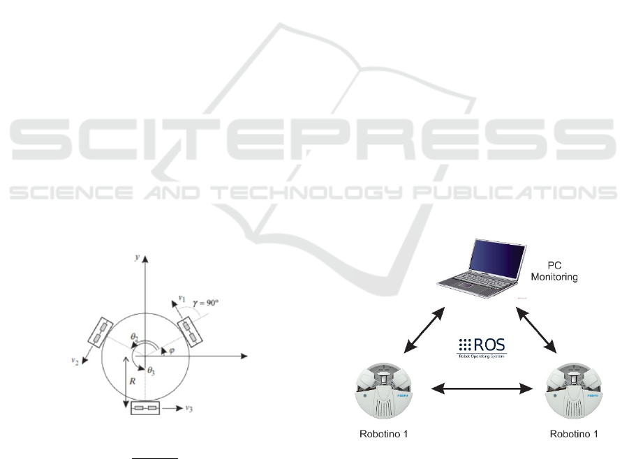
2.2 Kinematics of Robotino
Inverse kinematics on global coordinate are obtain by
calculating the translational velocity.
The final sentence of a caption must end with a
period.
Figure 1: Robotino on its own coordinate.
𝑣=
𝑥
+𝑦
(1
)
And angular velocity 𝜑 The velocity from each
wheel, in this case wheel 1 are defined by this
equation below:
𝑣
=𝑣
+𝑣
(2
)
The wheel velocity is part of the translational velocity
of the robot that are defined by this equation below:
𝑣
=𝑥 sin
𝜑
+𝑦 cos
𝜑
(3
)
A
nd an
g
ular velocit
y
defined as follow:
𝑣
=𝑅𝜑
(4
)
Distribute equation (3) and (4) to equation (2), then
we get the complete equation of the velocity of wheel
1:
𝑣
=𝑥 sin
𝜑
+𝑦 cos
𝜑
+𝑅𝜑
(5)
By using same method, we can calculate the velocity
of wheel 2 and 3 by adding the respective angle for
each wheel ϕ and other configuration of each wheel
respective to the global angle on (x,y) (0,0) of the
robots that are located in the center of the intersection
of robot wheel coordinate.
2.3 Robot Operating System
As stated in the previous sub section, Robotino Festo
were operated by embedded Linux Operation System
in a minicomputer. The linux version in the Robotino
Festo is Ubuntu Xenial. This Ubuntu Xenial has a
middleware called Robot Operating System (ROS)
that allows the robot to be controlled via Nodes that
are available in ROS packages. This Nodes can
publish or subscribe messages to topics. The topic
controls the actuators and sensors on the robot
directly by sending messages from Nodes. ROS
programming using both C++ and python.
Figure 2: General System for multi robotino control.
Robotino on the simulator are controlled by
sending a message from a control program to topics
of the actuator. The topics are in form of the
translational and angular velocity with its own
namespace for each robotino. The positions of the
robotino are known through odometry topics that are
iCAST-ES 2021 - International Conference on Applied Science and Technology on Engineering Science
1492
being published by the robots and subscribe to a
control program.
The detection of the obstacle is known by
subscribing sensors data to control program. Then the
sensors data that are obtained can be used to generate
the map of environment that has been travelled by
each robotino in form of 2D map. In t h i s study, the
environment based on the Robotics Laboratory in
Bandung Polytechnic for Manufacturing. The
generated map will display the path that robot has
been travelled and the obstacle that are detected
during the time of the robot travelled.
The entire system is focused to safely and
efficiently travelled the environment while
generating the information of the environment that
are travelled by robots. This can be further used for
both robots to travel back safely after knowing the
obstacle position is located and using more efficient
path planning and efficient cost trajectory algorithm.
3 GAZEBO ROS SIMULATION
This section discusses the simulation of the multi
robotino system on Gazebo simulator and present the
detailed information about the motion planning
algorithm of the system simulation.
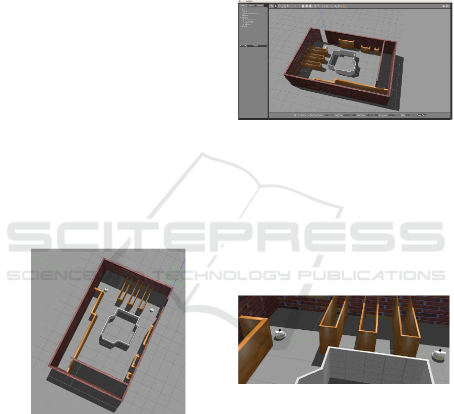
Figure 3: Map Figures in Gazebo.
4 SYSTEM MODEL ON GAZEBO
ROS
Robot Operating System allows to simulate a system
that has been planned on the previous section. There
are two type of simulation, Gazebo and Rviz. Each
simulation has different purpose, Gazebo simulator is
aimed as the visual representation and as the main
workspace to integrate the 3d models of the robotino
and environment to the ROS messages or services. Its
allows to simulate robot on an environment without
the real robot. While Rviz are mainly functioned to
display the data of the messages or nodes that are used
on the Gazebo simulator.
Figure 4: Gazebo Workspace.
The simulation requirement is the description of
the Robotino and environment. This simulation
includes the plugin for each component (sensors and
actuators) to work accordingly as the real component.
The description of the Robotino in ROS is as Unified
Robot Description Format (URDF)form that has the
function to describe the configuration of the robot
such as dimensions and plugins that are needed to
control the robot on Gazebo. The URDF file
formatted as XML file. Meanwhile the environment
of the simulation can be made directly on Gazebo
using building editor and model editor.
Figure 5: Multi Robotino on one environment.
The Rviz workspace that represent 2d map and
topics can be used for navigation planning. After all
environments are explored by the robots, 2d map can
be saved by using a map saver message.
Multiple Festo Robotino Navigation using Gazebo-ROS Simulator
1493
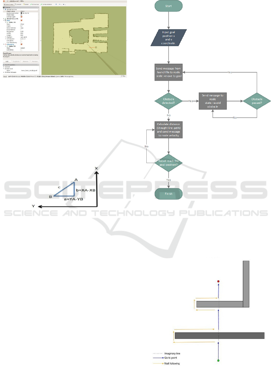
Figure 6: Rviz workspace.
4.1 Motion Planning Algorithm
Motion planning is the key to achieve the travelling
task of robotino on the environment without having
any collision and losses. It is required two
components, the path and the behaviour of Robotino
to avoid any obstacle while moving to the goal
position. The path will be selected as straight line
between the goal and the initial position.
Figure 7: Calculation of the Hypothenuse as the path
between point A and B.
The algorithm that are being used in this study are
Bug Algorithm. This algorithm has a simple thinking
process for each Robotino to be computed on their
system and two behaviours while executed, move to
goal behaviour and avoid obstacle. Move to goal
behaviour will calculate the initial position of each
robotino to their goal position and begin to move the
robot on a straight line between those position, if the
robot detect an obstacle, they begin to change the path
to avoid obstacle by following the contour of the
obstacle. In the same time, the algorithm calculates
the new position and try to maintain the straight line
path that were calculated on the beginning of the
algorithm. This process is repeated until the robots
reach the goal.
Figure 8: Motion Planning Algorithm.
While traversing the environment, each robotino
has to leave a trace of the obstacle that were
encountered and their traversable path. This allows
the robot to return to their original position by
choosing a more effective path and trajectory.
Figure 9: Visualization of the algorithm.
iCAST-ES 2021 - International Conference on Applied Science and Technology on Engineering Science
1494
5 EXPERIMENTAL
In the experiment scenario, each robot will travel to
the goal position on the other side of the room from
their initial position. Both robot will encounter
obstacle and trying to maintain the path that were
defined in the beginning of the algorithm, a straight
line between the initial position and the goal position.
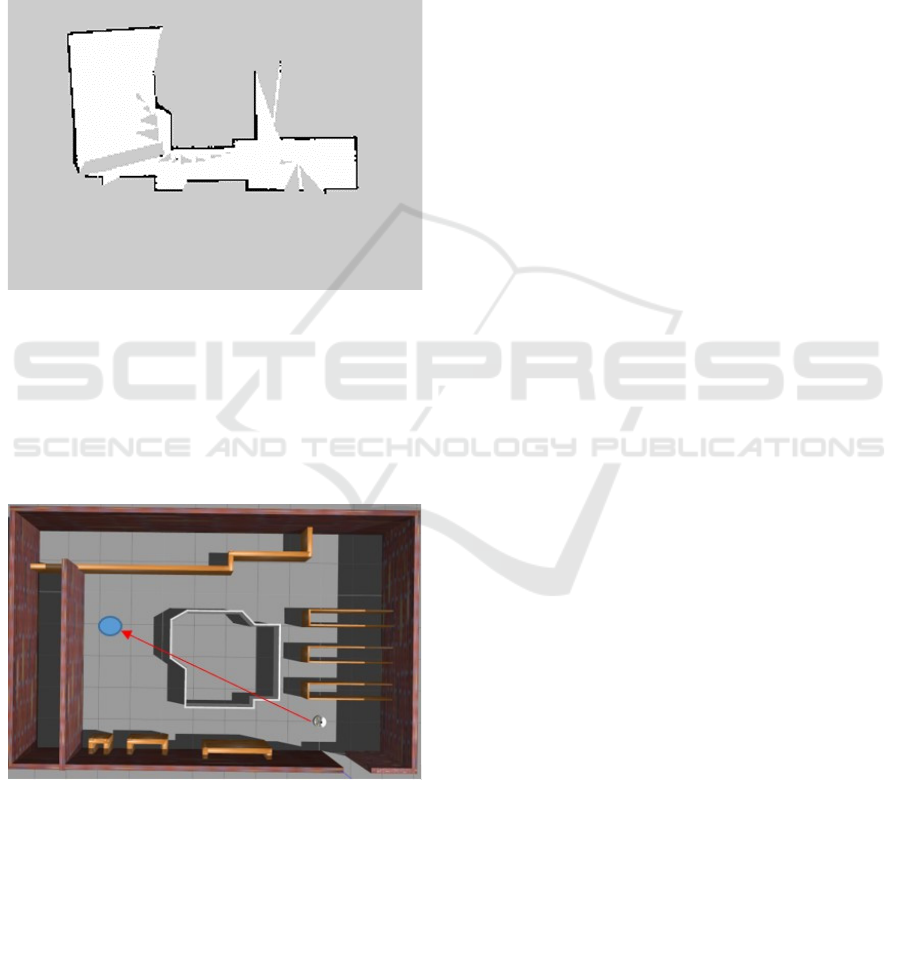
On Rviz, each robot will leave a 2d map along the
way to their goal as shown in Fig. 10.
Figure 10: 2D Map generated from the encounter of the
robot with obstacle.
As shown on the Fig. 11 that the original path (the
straight line) as the reference of the path for the robot.
Thus the robot will try to avoid the obstacle (the block
on the middle of the room) while trying to return the
original path.
Figure 11: Visualization of the algorithm.
6 CONCLUSIONS
The robots are able to travel safely to the goal position
while leaving a trace on the Rviz to visualize the
obstacles that have been encountered. However, the
Gazebo simulation has successfully spawn both
robots on the same environment with each namespace
attached to their topics. Bug Algorithm has its own
limitation, for instance while the robot trapped on U
shape obstacle. However, this can be overcome by
changing the obstacle avoidance behaviour to
circumnavigate the obstacle, therefore the robots will
select the traversable side point of the obstacle to
reach the goal position.
REFERENCES
Ali, T. Y., & Ali, M. M. (2015, November). Robotino
obstacles avoidance capability using infrared sensors.
In 2015 IEEE Jordan Conference on Applied Electrical
Engineering and Computing Technologies
(AEECT) (pp. 1-6). IEEE.
Anggraeni, P., Mrabet, M., Defoort, M., & Djemai, M.
(2018, October). Development of a wireless
communication platform for multiple-mobile robots
using ROS. In 2018 6th International Conference on
Control Engineering & Information Technology
(CEIT) (pp. 1-6). IEEE.
Borenstein, J., & Koren, Y. (1991). The vector field
histogram-fast obstacle avoidance for mobile
robots. IEEE transactions on robotics and
automation, 7(3), 278-288.
Draganjac, I., Miklić, D., Kovačić, Z., Vasiljević, G., &
Bogdan, S. (2016). Decentralized control of multi-AGV
systems in autonomous warehousing
applications. IEEE Transactions on Automation
Science and Engineering, 13(4), 1433-1447.
Klancar, G., Zdesar, A., Blazic, S., & Skrjanc, I.
(2017). Wheeled mobile robotics: from fundamentals
towards autonomous systems. Butterworth-Heinemann.
Mylvaganam, T., Sassano, M., & Astolfi, A. (2017). A
differential game approach to multi-agent collision
avoidance. IEEE Transactions on Automatic
Control, 62(8), 4229-4235.
Oltean, S. E., Dulău, M., & Puskas, R. (2010, May).
Position control of Robotino mobile robot using fuzzy
logic. In 2010 IEEE International Conference on
Automation, Quality and Testing, Robotics
(AQTR) (Vol. 1, pp. 1-6). IEEE.
Sabattini, L., Cardarelli, E., Digani, V., Secchi, C., &
Fantuzzi, C. (2016). Multi-AGV Systems in Shared
Industrial Environments: Advanced Sensing and
Control Techniques for Enhanced Safety and Improved
Efficiency. In Autonomous Industrial Vehicles: From
the Laboratory to the Factory Floor. ASTM
International.
Yan, R., Jackson, L. M., & Dunnett, S. J. (2017).
Automated guided vehicle mission reliability modelling
using a combined fault tree and Petri net approach. The
International Journal of Advanced Manufacturing
Technology, 92(5), 1825-1837.
Multiple Festo Robotino Navigation using Gazebo-ROS Simulator
1495
