
Numerical Analysis of the Effect of Serrated Fin to the Heat Transfer
in the Condenser
Febrian Kusumawardani, Lohdy Diana and Wahyu Nur Fadilah
Power Plant Engineering, Electronics Engineering, Polytechnic Institute of Surabaya, Surabaya, Indonesia
Keywords: Condenser, CFD, Shell and Tube, Fin, Serrated Fin, Annulus Tube.
Abstract: Condenser is one of the most important components in the power generation industry, which serves to
condense the output steam from low-pressure turbine for boiler feed water. Several ways can be used to
improve the performance of the condenser, one way is to add a serrated fin on the outer tube to lower the
temperature of the outlet. A serrated fin that is used has 0° and 30 segments per period, which is installed on
the tube with the diameter of the outer of 0.03175 m. This research was carried out by using the numerical
method of CFD 2D to compare the performance of the heat transfer on the tube without and with a serrated
fin on the variation speed of 7 m/s and 9 m/s. By inputting the parameters of the inlet of 350.15 °K, the
resulting value of the outlet serrated fin tube temperature which is lower than the annular tube (tube without
the serrated fin). On the simulation of the serrated fin tube with an inlet velocity of 7 m/s resulting outlet
temperature of 343.2 °K, lower than in the simulation on the annular tube which produces the outlet
temperature of 344.53 °K.
1 INTRODUCTION
Condenser serves to condense the steam output from
the low-pressure turbine into condensate water which
is then reused as boiler feedwater. In general, steam
power plants use the condenser shell and tube type,
which consist of a collection pipe that are located
inside a shell. Cooling water originating from
seawater will flow in the tube to condense the steam
output from the low-pressure turbine flowing in the
outer tube.
Figure 1: Shell and Tube Heat Exchanger.
The condenser has a very important influence on the
whole success of the series of processes in the steam
power plant, due to damage to the condenser will
result in the failure of mechanics or operational
failures that leads to the cessation of unit operation.
Besides, the decrease in the performance of the
condenser will also have a significant impact on the
efficiency of the fuel used.
Therefore, the condenser is required to have
performance as optimal as possible. A decline in the
condenser performance can be caused by many
factors, ranging from the presence of fouling, the
design of the tube, to the arrangement of the tube
which is less precise. One solution that can be done
to improve the performance of the condenser is to ad
fin on the outer side of the tube that aims to expand
the heat transfer surface. The more surface area and
increased turbulence of the fluid, the more the rate of
heat transfer will be. Based on research by Dian
Nilasari, it is known that the addition of a fin will
make the contour of the flow that occurs in the shell
side the random. Fin tube consists of several kinds,
such as annular, studded, plain, serrated, and others.
Various types of the fin can be affixed on the outer
side of the tube with some means, such as tension
winding using the adhesive bonding, soldered,
brazing, welding, or extrusion. Previous research has
been done by Reggy Arya Putra by comparing the
characteristics of the serrated fin tube and plain tube
using numerical methods of Computational Fluid
Dynamics (CFD). The result is known that the
Kusumawardani, F., Diana, L. and Fadilah, W.
Numerical Analysis of the Effect of Serrated Fin to the Heat Transfer in the Condenser.
DOI: 10.5220/0010966100003260
In Proceedings of the 4th International Conference on Applied Science and Technology on Engineering Science (iCAST-ES 2021), pages 1397-1404
ISBN: 978-989-758-615-6; ISSN: 2975-8246
Copyright
c
2023 by SCITEPRESS – Science and Technology Publications, Lda. Under CC license (CC BY-NC-ND 4.0)
1397
serrated fin has the better heat transfer characteristics,
due to turbulence of flow around the tube increased
compared with the addition of plain tube. Therefore
the author researched by comparing the serrated fin
tube with the annular tube to find out how much the
influence of the addition of fin on heat transfer
performance in the condenser. This study contributes
to the investigation of the flow phenomenon across
the tubes which is not possible experimentally.
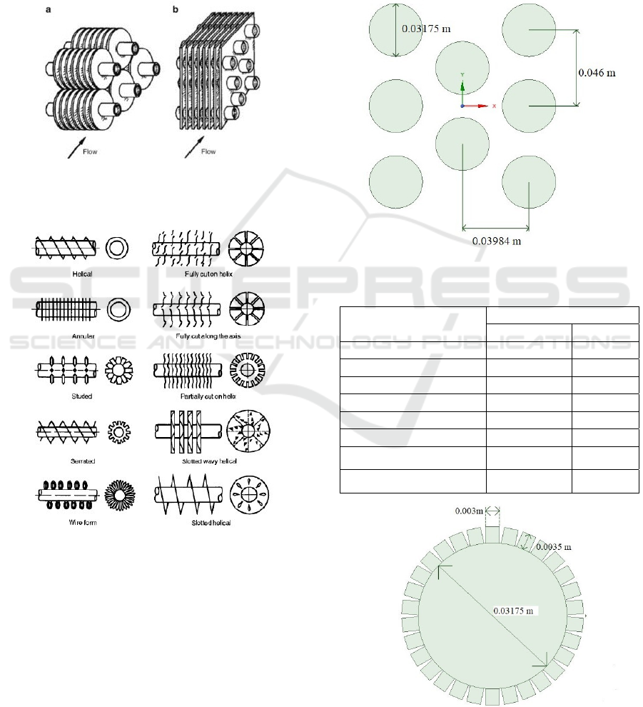
Figure 2: Tube Fin Exchanger Configuration. (a)
Individually Finned Tubes. (b) Flat Fin with Continuous
Form on an Array of Tubes.
Figure 3: Type Fin Tube.
2 RESEARCH METHODE
The author researched by using the numerical
methods of CFD to determine the effect of the
serrated fin to the heat transfer. The simulation is
performed in dimensionless 2D by comparing the
heat transfer that occurs between the annular tube and
serrated fin tube at different speeds, 7 m/s and 9 m/s.
From this research, qualitative and quantitative data
are obtained.
2.1 Tube Design
The making of the design was done in SpaceClaim
with the parameters as in Table 1, using the fins with
0° angle in accordance to researched by Lemouedda
and Franz.
Figure 4: Design of Annulus Tube.
Table 1: Parameter Design of Geometry Serrated Fin Tube.
Design
Design Parameter
Value Unit
Tube OD 0.03175 m
Fin High 0.0035 m
Fin Angle 0
°
Fin Width 0.003
Tube Arrangement Staggered
Tube Bank Angle 60
°
Transversal Pitch 0.046 m
Longitudinal Pitch 0,03984 m
Figure 5: Design of Serrated Tube.
iCAST-ES 2021 - International Conference on Applied Science and Technology on Engineering Science
1398
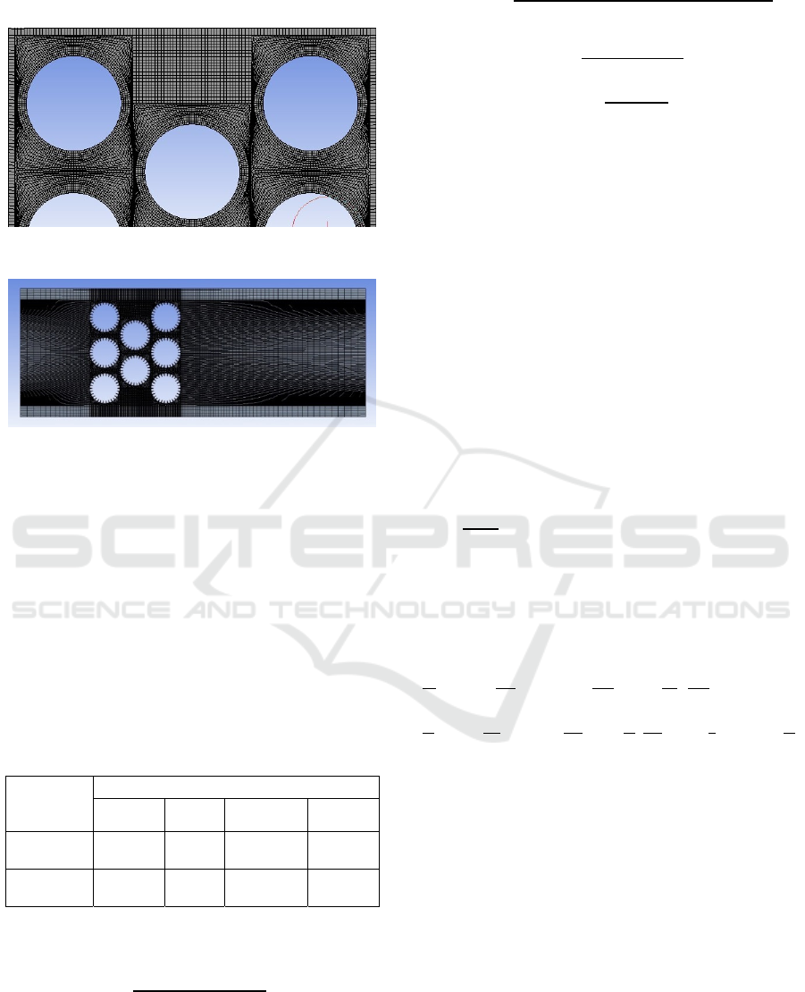
2.2 Meshing
Figure 6: Details of Meshing Annulus Tube.
Figure 7: Meshing Serrated Fin Tube.
Meshing is the enumeration of the geometry into
small parts that will be done the calculations for
computing. Tightly meshing will produce a value
close to the accuracy. Since there are significant
conditions gradation around the tube, such as
decreased temperature, increased speed, and the
other, the meshing around the tube area is done very
tightly. The meshing type used in the simulation is
Quadrilateral-Map. The results of meshing on the
simulation can be seen in Figure 6 and Figure 7 While
the parameters and the quality of the meshing can be
seen in Table 2.
Table 2: Parameter Meshing.
Tube
Type
Parameter Meshing
Element
Mesh
Nodes
Orthogonal
Quality
Skewness
Quality
Annulus
Tube
50704
51960 0,92225
0,17515
Serrated
Tube
40043
42527 0,9859
6,62E-02
Equation 1 is used to get the value of the temperature
of the surface of the tube.
𝑇
=
/
)
(
/
)
(1)
Equation is used to get the value of the temperature
of the surface fin.
𝑇
=
[
(
)
(
/
)]
(
/
)
(2)
𝜂
=
(3)
𝜂
=
(
)
(4)
Furthermore, the method of solution used is
SIMPLEC and spatial discretization on the second
order upwind for all the parameters. To improve
accuracy of the simulation, the value 10
is set in
the residual setting element. The latter initialization is
done using the method of hybrid initialization, before
finally starting the iteration to get the result
convergent in steady conditions.
2.3 Processing
In this stage, processing is done by settings the solver
model, viscous models, the determination of the type
of material, the determination of the boundary
conditions, control & monitoring conditions, and
initial conditions. In the solver model, it enables the
energy equation to support the completion of the heat
transfer, which uses the equation 5 of energy transport
()
+ ∇.[𝑉
(
𝜌𝐸+ 𝜌
)
= ∇. 𝑘
∇𝑇−
∑
ℎ
𝐽
+
𝜏
. 𝑉+ 𝑆
(5)
While for the turbulence modeling of selected k-RNG
(Renormalization Group) for the support of
turbulence in the outer side of the tube is using the
transport equation 6.
(
𝜌𝑘
)
+
(
𝜌𝑘𝑢
)
=
(µ +
µ
)
+ 𝑃
−𝜌𝜀
(
𝜌𝜀
)
+
(
𝜌𝜀𝑢
)
=
(µ +
µ
)
+ 𝐶
𝑃
−𝐶
∗
𝜌
(6)
This simulation is using two materials, one is
water vapor wich flowing in the shell side, the other
is titanium which is used as the material for the tube
and the fin. The value of the properties of water-vapor
and titanium is analyzed based on the average
temperature of the fluid within the shell. Next,
boundary condition is determined. The boundary
conditions set in this simulation are shown in Table 3.
Numerical Analysis of the Effect of Serrated Fin to the Heat Transfer in the Condenser
1399
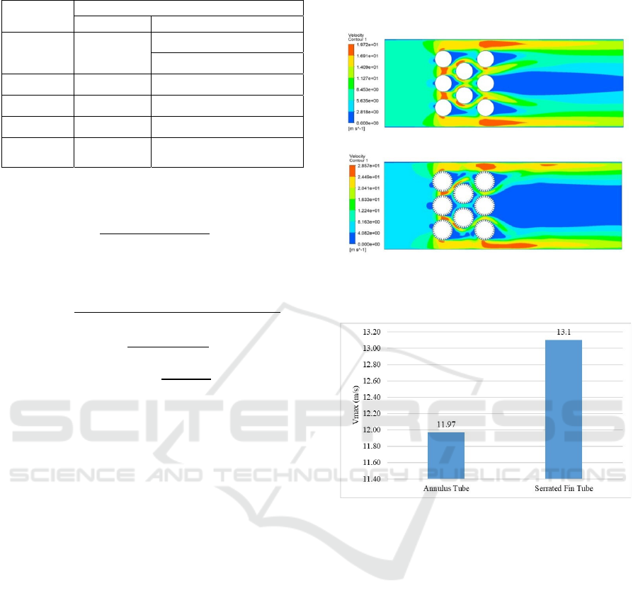
Table 3: Parameter Boundary Conditions.
Boundary
Condition
Boundary Conditions Parameter
Type Parameter
Inlet Velocity
Velocity = 7 & 9 m/s
Temperature = 350.15° K
Outlet Outflow
Tube Wall
Temperature = 315.13° K
Fin Wall
Temperature = 315.9° K
Up and
Down Wall
Symmetry
Equation is used to get the value of the temperature
of the surface of the tube.
𝑇
=
(
/
)
(
/
)
(7)
Equation is used to get the value of the temperature
of the surface fin.
𝑇
=
[
(
)
(
/
)]
(
/
)
(8)
𝜂
=
(9)
𝜂
=
(
)
(10)
Furthermore, the method of solution used is
SIMPLEC and spatial discretization on the second
order upwind for all the parameters. To improve
accuracy of the simulation, the value 10
is set in
the residual setting element. The latter initialization is
done using the method of hybrid initialization, before
finally starting the iteration to get the result
convergent in steady conditions.
2.4 Post-processing
The results of numerical simulations will be analyzed
qualitatively and quantitatively. The qualitative
analysis will be presented in the form of the image
velocity and temperature distribution, while
quantitative analysis will be presented in the form of
a bar chart to determine the effect of serrated fin
against heat transfer characteristics, such as Reynolds
Number, Nusselt Number, and heat transfer
coefficient.
3 RESULT AND ANALYSIS
The research method is a numerical study that is
completed computationally with the results of the
analysis using fluid mechanics theory and heat
transfer.
3.1 Comparison of Speed Distribution
for Annulus and Serrated Fin Tube
(a)
(b)
Figure 8: Comparison of Speed Distribution (a) Annulus
and (b) Serrated Fin Tube.
Figure 9: Vmax Comparison Chart for Annulus and
Serrated Fin Tube.
Image of flow speed contour through tube bank is
taken at the time of a speed of 7 m/s, both for the
simulation of annular tube or serrated fin tube. Based
on Fig. 8 obtained qualitative data in the form of a
contour image of speed with the indicator red
indicates the highest speed and blue color to
represents the speed of the lowest. On the simulation
of annular or serrated fin tube, maximum speed value
is obtained at the area of the transverse rows of the
first, which is due to the occurrence of the narrowing
of the area. While on the part of the transverse rows
of the second and third has been a decreased in the
speed of the fluid flow caused by flow colliding with
the tube in the front (Shah and Sekulic, 2007). Based
on Fig. 8 the back of the tube is blue, both on the tube
line of the first, second or third, which is caused by
the flow of fluid that has passed through the pipe
having the separation of the flow and creates a wake,
which is the area that a deficit of momentum.
iCAST-ES 2021 - International Conference on Applied Science and Technology on Engineering Science
1400
The value of Vmax between the annular tube and
serrated fin tube will be presented quantitatively in
Fig. 9 Based on the simulation results, the addition of
the serrated fin has a Vmax of 13.1 m/s, which is
larger compared to the annular tube, which produces
Vmax value only at 11.97 m/s. The high value of the
Vmax in the simulation of the serrated fin tube due to
the existence of the fin on the outside of the tube will
enlarge the heat transfer surface and narrow the
distance of the transverse and longitudinal between
the tube, causing heat transfer occurring to be better
(Bergman et al.). The existence of the serrated fin will
also further randomize the flow of the fluid, which
causes the value of Reynolds Number is also greater.
The more random or turbulent fluid flow, then the
heat transfer that occurs would be even better.
3.2 Comparison of Temperature
Distribution for Annulus and
Serrated Fin Tube
(a)
(b)
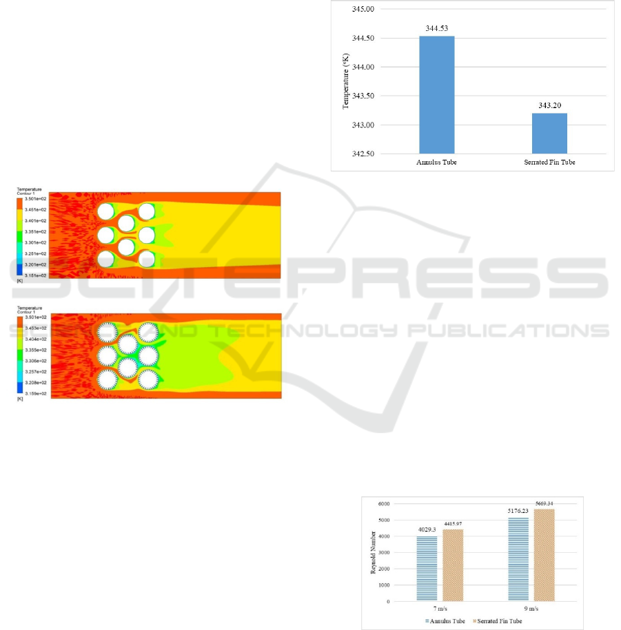
Figure 10: Comparison of Temperature Distribution (a)
Annulus and (b) Serrated Fin Tube.
Image of the temperature contours which passes
through the tube bank is taken at the time of a speed
of 7 m/s, both on the simulation of the annular tube or
serrated fin tube. Based On Fig. 10 obtained
qualitative data in the form of image contour of
temperature with indicator red color represents the
highest temperature and the blue color to shows
lowest temperature. On the simulation, the inlet
temperature parameters input is 350.15°K with the
temperature conditions uniform, either for the
simulation of annular tube or serrated fin tube. While
cooling water temperature is low within the tube,
enabling the decrease of the temperature at the outlet
side because there was a heat transfer arround the tube
bank, which heat will flow from the high
temperatures heading to the low temperatures. Based
on Fig. 10 obtained qualitative data in an annular tube
is dominated by the yellow color on the outlet, thus
indicating that fluid wasted still have high
temperatures. Different from the qualitative data
serrated fin tube which is dominated by light green
color on the side of the outlet, which indicates that the
fluid has a lower temperature because it has happened
more heat transfer around the tube bank.
Figure 11: Temperature Comparison Chart for Annulus and
Serrated Fin Tube.
Based on Figure 11 obtained quantitative data outlet
temperature of the annular tube is 344.53 °K, which
means it has 5.62 °K difference from the temperature
of the inlet. While the outlet temperature serrated fin
tube is 343.20 °K, the difference 6.95 °K from the
temperature of the inlet. Thus, it means the
installation of serrated fin tube makes heat transfer
around the tube bank better, because of the serrated
fin will make the surface of the heat transfer is more
extensive if compared to the annular tube. The greater
the area of the heat transfer surface, the better the heat
transfer occurs.
3.3 Analysis of the Effect of Speed on
Reynold Numbers for Annulus and
Serrated Fin Tube
Figure 12: Reynold Number Comparison Chart for Annulus
and Serrated Fin Tube at 7 m/s and 9 m/s Speed.
In this simulation, the speed is varied by 7 m/s and 9
m/s respectively, both on the annular tube or serrated
Numerical Analysis of the Effect of Serrated Fin to the Heat Transfer in the Condenser
1401
fin tube, to determine the effect of speed changes
against the Reynolds Number. The Reynolds Number
is a dimensionless number used to determine the type
of fluid flow that occurs. The Reynolds Number is
also defined as the ratio between inertia force with the
viscosity force in the boundary layer speed. The low
Reynolds Number value will cause the force of inertia
is not so significant compared to the viscosity force.
While the high Reynold Number value has high
inertial force, which has more significance than
viscocity force. The high value of the Reynolds
Number will make boundary layer of the fluid thinner
because it is depressed by the force of inertia. The
thinness of the boundary layer will increase the
amount of fluid that is high speed so that the process
of heat transfer will occur faster. The value of
Reynolds Number is also very dependent on the value
of Vmax, the greater the value of the maximum
velocity then the value of the Reynolds Number will be
even greater.
𝑅𝑒𝐷=
µ
(11)
𝑉
=
()
𝑉 (12)
Based on Figure 12 The obtained value of Reynolds
Number is different in the simulation of annular and
serrated fin tube. Simulation of serrated fin tube
generates large Reynolds Number, each worth
4415.97 at a speed of 7 m/s and 5669.34 on the speed
of 9 m/s. While the simulation of the annular tube
produces only the value of the Reynolds Number of
4029.3 at a speed of 7 m/s and 5176.23 on the speed
of 9 m/s. The high Reynolds Number in the
simulation of the serrated fin tube shows that the
addition of a serrated fin on the outside of the tube
will make the fluid flow more random. When the inlet
velocity increases, then the value of Vmax will be
greater, so also with the Reynolds Number.
3.4 Analysis of the Effect of Speed
Changes on Nusselt Numbers for
Annulus and Serrated Fin Tube
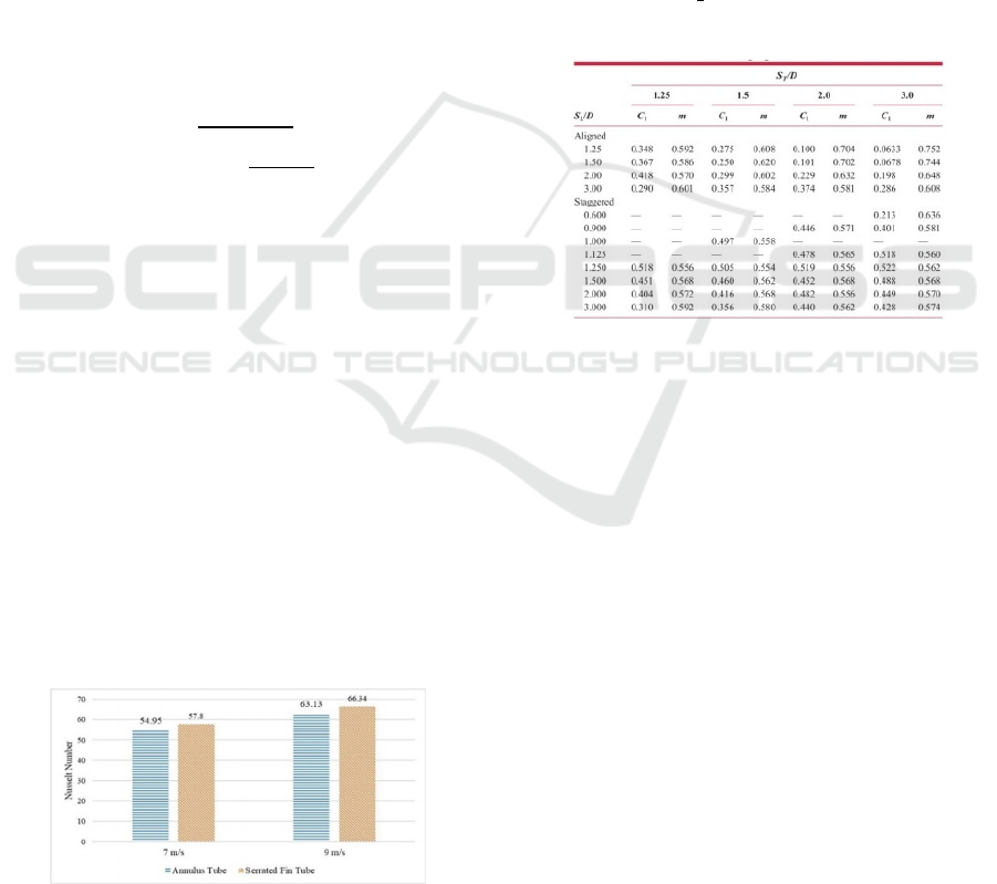
Figure 13: Nusselt Number Comparison Chart for Annulus
and Serrated Fin Tube at 7 m/s and 9 m/s Speeds.
Based on Figure 13 the known Nusselt Number will
change along with the increase of speed. A Nusselt
Number is a dimensionless number of the ratio of heat
transfer by convection and conduction on the
boundary condition of the fluid. Increasing speed will
increase the value of the Reynolds Number because
the thickness of the boundary layer is getting thinner
so the amount of high speed fluid is increasing. The
depletion of the boundary layer of the fluid will cause
an increase in the value of the Nusselt Number, and
vice versa. Therefore, the increasing Nusselt Number
will also make the heat transfer the better. The value
of Nusselt Number is also influenced by the Prandtl
Number.
Nu
=
1,13 C1 ReD
𝑃𝑟
𝑁
10
2000 𝑅𝑒
,
40000
𝑃
0,7
(13)
Figure 14: Constant Value C1 and m.
Based on Figure 13 it can be known that the Nusselt
Number on the simulation of the serrated fin tube is
good compared with the annular tube, both at a speed
of 7 m/s or 9 m/s. On the simulation of the annular
tube with a speed of 7 m/s produces only the Nusselt
Number of 54.95 and at a speed of 9 m/s will produce
a Nusselt Number of 63.13. While in the simulation
of the serrated fin tube will produce a Nusselt Number
of 57.8 at a speed of 7 m/s and will be increased to
66.34 at a speed of 9 m/s. Thus it can be concluded
that the addition of a serrated fin on the outside of the
tube will produce large Nusselt Number and the heat
transfer that occurs in the tube bank is better.
3.5 Analysis of the Effect of Speed
Changes on the Convection
Coefficient for Annulus and
Serrated Fin Tube
In theory the greater the value of the coefficient of
convection means better heat transfer. There are two
types of convection which occur, namely natural
iCAST-ES 2021 - International Conference on Applied Science and Technology on Engineering Science
1402

Figure 15: Graphic Comparison of Convection Heat
Transfer Coefficients for Annulus and Serrated Fin Tube at
7 m/s and 9 m/s Speeds.
convection and forced convection. Natural
convection occurs if there is no fluid velocity that
affects the heat transfer process. While forced
convection occurs when the heat transfer process is
influenced by the speed of the fluid occurs in the
vicinity. In this simulation occurs forced convection
heat transfer, because of the speed of the input on the
inlet. Heat transfer by convection occurs because
water-vapor that has a higher temperature will release
heat to the walls of the fin or the tube that have lower
temperatures. The value of the coefficient of
convection is also affected by the Reynolds Number.
The greater the value of the Reynolds Number, the
greater the process of convection that occurs. Besides,
the value of the coefficient of convection is also
affected by the Prandtl Number and thermal
conductivity of water vapor. The Prandtl Number is
defined as the ratio of diffusivity of momentum to
diffusivity thermal, while thermal conductivity is
defined as the rate of heat transfer by conduction
through the area of the cross-section of the unit
material.
𝐻
=
.
.
.
.
,
.
(14)
Based on Figure 15 it is known that the addition of
the serrated fin will result in the better value of the
coefficient of convection heat transfer compared to
the annular tube, both at a speed of 7 m/s or 9 m/s. On
the simulation of the serrated fin tube with a speed of
7 m/s the convection heat transfer coefficient is
produced at 883.41
°
, and increased to 1000.96
°
at a speed of 9 m/s. While in the simulation the
annular tube produces the convection heat transfer
coefficient is produced at 843.84
°
at a speed of 7
m/s and increased to 956.44
°
at a speed of 9 m/s.
Thus the addition of a serrated fin on the side of the
outer tube can increase the occurrence of heat
transfer, which is proven by the increasing coefficient
of heat transfer by convection.
4 CONCLUSIONS
Based on the simulation results, it can be concluded
that the addition of a serrated fin on the side of the
outer tube can improve the heat transfer that occurs
around the tube banks because the outlet temperature
is low. With the same temperature inlet input 350.15
°K, at a speed of 7 m/s the simulation of an annular
tube produces only the outlet temperature of
344.53°K, while in the simulation of the serrated fin
tube produces the outlet temperature of 343.2 °K.
Besides, the use of serrated fin tube can also increase
the Reynolds Number, Nusselt Number, and
convection heat transfer coefficient around the tube
bank. On the simulation of the serrated fin tube with
a speed of 7 m/s produced a Reynolds Number of
4415.97, Nusselt Number of 57.8, and the convection
heat transfer coefficient of 883.41
°
. While in the
simulation of the annular tube with a speed of 7 m/s
only produces a Reynolds Number of 4029.3, Nusselt
Number of 54.95, and coefficient of convection heat
transfer by 843.84
°
. To further improve the heat
transfer performance of the serrated fins, further
research could increase the number of segments in
each period to expand the heat transfer surface. The
more surface area of an object, the better the heat
transfer that occurs.
REFERENCES
R. W. Serth. (2007). Process Heat Transfer Principles and
Application, First Edit. Elesevier.
D. P. Bergman, Therodore. Lavine, Adrienne S. Incropera,
Frank P. Dewitt, Fundamentals of Heat and Mass Trans-
fer Seventh Edition, Seventh Ed. John Willer & Sons.
D. Nilasari. (2017). Analysis of Pitch Tube Angle
Arrangement Effect in Fluid Flow Characteristics and
Heat Transfer.
Reggy A. Putra. (2017). Fin Shape Analysis for Thermal
Efficiency on High Pressure Economizer Heat Recovery
Steam Generator PLTGU PT. PJB-UP Gresik.
R. K. Shah and D. P. Sekulic. (2007). Fundamentals of Heat
Exchanger Design. New Jersey: John wiley & Sons, Ic.
A. Lemouedda, A. Schmid, E. Franz, M. Breuer, and A.
Delgado. (2011). Numerical investigations for the
optimization of serrated finned-tube heat exchangers.
Appl. Therm. Eng., vol. 31, no. 8–9, pp. 1393–1401.
A. Kumar and A. Layek. (2019). Numerical Analysis for
Nusselt Number and Heat Transfer Augmentation on
Numerical Analysis of the Effect of Serrated Fin to the Heat Transfer in the Condenser
1403

Solar Air Heater Roughened with Square Rib Roughness
on the Absorber Plate,” Agribus. J., vol.13, no.1, pp. 31–
36.
iCAST-ES 2021 - International Conference on Applied Science and Technology on Engineering Science
1404
