
Balancing Control System for Humanoid Robot using
Pressure Sensor
Novian Fajar Satria
1
, Eko Henfri Binugroho
1
and Ibrohim Mujahid Robbaniy
2
1
Politeknik Elektronika Negeri Surabaya, Sukolilo, Surabya, Indonesia
2
Department of Mechanical and Energy, Surabaya, Indonesia
Keywords: Humanoid Robot, Balancing Control System, Pressure Sensor.
Abstract: Balancing the control system becomes one of the important topics in special robots is a humanoid robot. The
sensors used for balance control mostly use the inertia measuring unit (IMU) sensor. The sensor can detect
the value and level of the tilt, displacement, and gravity of the robot. By using the reference from the sensor
data, the value of the data in the balance control system will be made to make the humanoid robot can walk
and move in a balanced manner. Not only the IMU sensor can be used in the application for balance control,
one of which is to use a pressure sensor. The working system of this sensor is the pressure force received from
the sensor that will be used as a reference for the balance data values in the robot humanoid balance control
system. So that the humanoid robot can adjust to the conditions of the road being passed while maintaining
its balance and not falling. the pressure sensor will be placed on the foot of the humanoid robot foot as the
pedestal and the reading of the tilt data each foot of the robot will be installed 2 pressure sensors to get the
value of the slope data which is in the position of the direction forward and back when the humanoid robot
moves and steps. Through a series of testing processes of the balance control system in the humanoid robot,
it was found that the robot can maintain its equilibrium position in the incline to 15 degrees, and the average
error value obtained from reading the data on the pressure sensor is 0.13%.
1 INTRODUCTION
One of the most important things to make a humanoid
robot is balancing control system. It can determine the
success of a humanoid robot in carrying out
movements such as stabilizing the body in an inclined
plane, walking and dancing. Without balancing
control system, the robot will have difficulty making
movement and can cause the robot fall also fail to do
something. Until now, balancing control system of
humanoid robots is still developed, such as static
balance, dynamic even the ability to determine
movement when there is a loss of balance. To make it
real about balancing control system of humanoid
robot there needs a control system can control the
actuator of the robot in order to realize a balanced
condition (Riananda, 2018). Kind of sensors are
usually used for balancing control system is
gyroscopes, accelerometers, and magnetometers.
Now, 3 kind of that sensor be combined into a more
complex sensor module known as IMU (Inertial
Measurement Unit) Sensor.
IMU sensor can’t use in humanoid robot because
the balancing control system difficult to get data
sensor while this robot walking and dancing. The
degree of the sloped surface is set to vary from 5° to
the maximum extent of robot ability. The test results
show the addition of the balance control system gives
ERISA robot capability of walking on the sloped
surface up to 10 degree (Alasiry, 2018).
To resolve this problem, in this research using
pressure sensor and will placed on both sole of foot
the robot to balancing control system. This sensor
consists of load sensor and pressure sensor where
every difference condition in load and pressure of this
sensor will produce different resistance value. From
these differences, it can be used as a reference in
regulating the balance of the robot by means of each
pressure sensor that will be placed on the two legs of
the robot. On each leg there are 2 sensors that function
to measure the load and pressure at the 2 outer points
of the foot to be able know the compressive force at
each point. From that we can draw the resultant force
from each of these points. Result of processing from
the resultant force to these 2 points will bring up a
Satria, N., Binugroho, E. and Robbaniy, I.
Balancing Control System for Humanoid Robot using Pressure Sensor.
DOI: 10.5220/0010965400003260
In Proceedings of the 4th International Conference on Applied Science and Technology on Engineering Science (iCAST-ES 2021), pages 1359-1364
ISBN: 978-989-758-615-6; ISSN: 2975-8246
Copyright
c
2023 by SCITEPRESS – Science and Technology Publications, Lda. Under CC license (CC BY-NC-ND 4.0)
1359

coordinate of the fulcrum on the soles of the robots.
From the displacement of the fulcrum it is used as a
robot balance system.
Figure 1: Humanoid Robot.
2 ROBOT DESIGN
2.1 Mechanical Design
Total Dof (Degree of Freedom) from Robot is 29 and
parts detail from that DoF in Table 1. Robot was made
from CAD software to make the design from the leg
until the neck. And also using CAM software to make
generate code (G-Code) from that design to
realization the model using machine CNC. To make
all of parts from Robot using type of motor is servo
dynamixel MX-28:
Table 1: DoF Part Detail of Humanoid.
No Body Part Number of DoF
1 Hea
d
3 (Neck)
2 Stomach 1 (Stomach)
3 Waist 1
(
Waist
)
4 Hand
6
(
Shoulder
)
2
(
Elbow
)
4 (Wrist)
5 Feet
6
(
Waist
)
2
(
Knee
)
4 (Ankles)
Total Number of DoF 29 DoF
2.2 Electrical Design
To control the overall performance, use ARM
microcontroller, it has frequency up to 168MHz. To
calculate value of kinematic and accessing the sensor
also communicate with PC, robot use the main
controller that is ARM SFM32F4. The data read from
FSR sensor. Since the reading result is analogue data,
it needs to be converted to get the angle value using
ADC.
Figure 2: Electrical System Diagram.
3 CONTROL SYSTEM DESIGN
To keep stabilize balancing of using control system.
This control system will maintain the value COG
from body robot to make the body robot become
upright and stable. This is the basis of stability system
so the robot able to compensate for external
influences (Saputra, 2016). The kinematic model of
pitch and roll position control from show on figure 3.
The kinematic model can be described as two
inverted pendulum which servo motor position in
stomach of robot as roll compensator, and then servo
motor position in the waist of robot as pitch
compensator (Zafar, 2016). Servo motor place in roll
position compensate the right and left. And to control
front and back falling direction is servo position in the
pitch.
Figure 3: Kinematic Model of pitch pose control system.
3.1 Pressure Sensor and Design
Pressure sensors applied in humanoid robots use the
FSR400 FSR model. This FSR is the main sensor used
to measure the force caused due to the pressure acting
on each FSR sensor later. The use of this FSR sensor
is very easy. Because basically the FSR sensor has an
output in the form of an obstacle that changes with the
iCAST-ES 2021 - International Conference on Applied Science and Technology on Engineering Science
1360
changing forces acting on this sensor so that by using
the voltage divider circuit this sensor can be read the
output voltage.
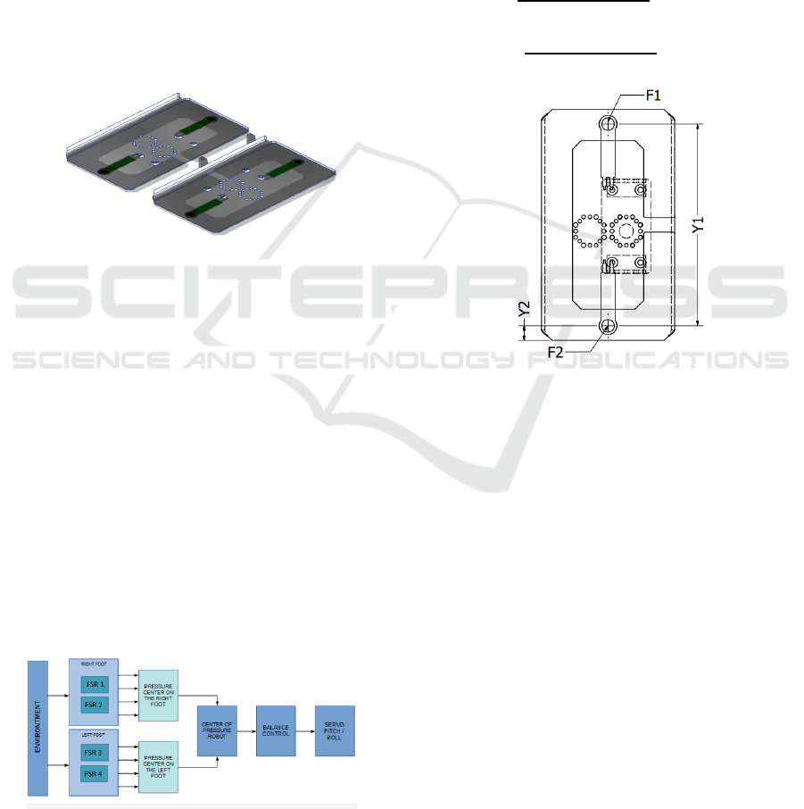
3.1.1 Placement of Pressure Sensors on the
Robot Root
The design of the FSR placement design on robot foot
is in figure 4. From figure 4, it appears that on each
foot there are 2 pieces of FSR attached. This FSR is
placed at the end of each foot. The purpose of laying
2 FSR on the ends of the foot is that the distribution of
the center of pressure is easy and can know the
condition of the pressure sensor that is not tread when
on an uneven surface. The laying of the FSR at the end
of the foot will provide information on the condition
of the robot's pressure when standing.
Figure 4: Layout Design Place of Sensors on the Robot
Root.
From the results of the design, FSR placement on
robot foot was carried out. The results of the
realization of the FSR placement on robot foot are in
figure 34. It appears that in one foot requires 2 FSR,
so that in one robot it requires 4 FSR to get
information on robot pressure. In the design, the area
of foot is made with maximum dimensions.
Determination of the maximum area of robot foot is
determined based on the height of the robot and the
height of the center of mass on the body of the robot.
3.1.2 Pressure Sensor Control Design
From the 2 sensors in each leg the data center pressure
on the foot is then processed to become the center of
pressure on the robot. And then the data will be used
as a parameter for robot balance control.
Figure 5: Layout Design Place of Sensors on the Robot
Root.
3.1.3 Positioning of the Centre of Pressure
on The Foot
To get the center of pressure on the robot, each foot
is calculated first on the value of the pressure pressed
by each foot. After obtaining this value, then the
center of pressure is sought on one of the foot. To get
the center of pressure on one of the foot can use
equations (1) for the position of coordinates for the
left foot and equations (2) for the position of
coordinates for the right foot. Figure 6 shows the
position of each size.
𝑌𝑐𝑜𝑝𝑟=
(
𝐹1.𝑌1 + 𝐹2.𝑌2
)
𝐹1 + 𝐹2
− 𝑌1/2 (1)
𝑌𝑐𝑜𝑝𝑙=
(
𝐹1.𝑌1 + 𝐹2.𝑌2
)
𝐹1 + 𝐹2
− 𝑌1/2 (2)
Figure 6: Positioning of the centre of pressure on foot.
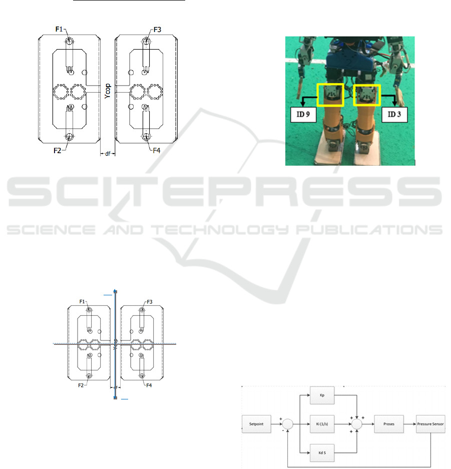
3.1.4 Determining the Position of the CoP
Robots
The location of Center Of Position (COP) can evaluate
the stability when humanoid robot walking. In this
section, how to measurement COP of humanoid robot
is discussed in detail. Style movement walking of
Humanoid robot use single or multiple support phase
and because of that the COP measurement discussions
cover both of them. COP be an important role for the
stability of walking humanoid robot (Sukha, 2015).
The force under the feet during the walking robot can
be estimated by the vertical force reflected from the
ground. More dynamic phenomena needed for ZMP
as long as humanoid robots increase complications
increase gait. Therefore, this study proposes to
simplify the evaluation of stability by using force
sensors to measure COP.
When the position of the center of pressure on
each foot is obtained, then the data is sent to the
controller on the robot body. The data is then
Balancing Control System for Humanoid Robot using Pressure Sensor
1361
processed to obtain the position of the center of
pressure on the robot that is retracing the current
conditions. In addition to the position data center of
pressure, the pressure data on each sensor is also sent
to ensure if there is a data transmission error. In
finding the position of the center of pressure on the
robot you can use Equations (3) for y coordinates.
Figure 7 shows the position of the center of pressure
obtained on the robot.
𝑌𝑐𝑜𝑝=𝑌𝑜
(
𝐹1 + 𝐹2 + 𝐹3 + 𝐹4
)
∗𝑑𝑌
𝐹𝑡𝑜𝑡𝑎𝑙
(3)
Figure 7: Determining the Position of the CoP Robots.
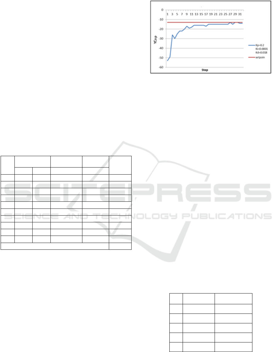
3.2 Balancing Control System
The position of the robot pressure center is in a
balanced condition which is at the position of
coordinates (0; 0) (Al-Shuka, 2016). In these
conditions the robot is at the center of the mass and
gravity of the robot. So that the coordinate point (0;0)
is the setpoint value of the robot.
Y+
Y-
Figure 8: Centre of pressure Robot.
When the position from the robot's center of pressure
is not in the position of coordinates (0; 0), the
condition of the robot would be unstable. The position
of the center of pressure that is read will be reduced
by coordinates (0; 0) which is the setpoint on the
robot, so that the error value is obtained, which will
then be entered into the PID controller as shown in
figure 9. In the PID control tuning Kp, Ki and Kd is
done to get a fast response to reach steady state.
As the concept of the Inverted Pendulum PID
control will drive ID servo 3 and 9 on the ankle part
of the robot. When the position of the robot COP from
the sensor is in front of the sole of the foot, which
means that the robot is leaning forward, the servo will
move backwards so the robot does not fall. Opposite
from that, when the position of the robot COP from
the sensor is behind the sole of the foot, which means
that the robot is leaning backwards, the servo will
move forward so the robot does not fall.
Figure 9: Servo ID.
When the position of the robot's center of pressure is
not in the position of coordinates (0;0), the robot will
be in an unbalanced condition. So it is necessary to
determine the back movement so that the robot
returns to a balanced position. To get back movement
can be calculated using the PID control so that the
response of the given back motion becomes smoother
for the movement of the robot. The position of the
center of pressure that is read will be reduced by
coordinates (0;0) which is the setpoint on the robot,
so that the error value is obtained. The PID control
will determine the back motion which will then be
calculated with the default servo position data to
control the value of the new servo movement. In the
PID control tuning Kp, Ki and Kd is done to get a fast
response to reach steady state.
Figure 10: Control PID Diagram.
iCAST-ES 2021 - International Conference on Applied Science and Technology on Engineering Science
1362
4 EXPERIMENTAL RESULT
Chapter of system testing and analysis, will be
explained about the data obtained from the results of
testing the pressure sensor on the robot during the
process, and analysis of the data obtained.
4.1 Testing the Centre of Pressure in
One Foot
For Testing the center of pressure on one foot in this
case to compare the center pressure data obtained with
the center pressure data obtained through calculations
in Equations (1) and Equations (2). Testing in this
section is done by placing the object on each FSR with
known pressure. Then the error is calculated between
the calculation results and the results obtained. Table
2 show the results of testing the center of pressure on
one right foot.
Table 2: Test Results on Right Foot Tread.
No
.
Force Data
Calculation
Resul
t
Testing
Resul
t
Error
F1 (N) F2 (N) Ycop Ycop
1 0,55 5,34 -46,15 -46,13 0,05%
2 0,26 4,38 -50,39 -50,36 0,06%
3 0 10,16 -56,75 -56,75 0,00%
4 0,18 9,05 -54,54 -54,6 0,12%
5 2,03 5,01 -24,02 -24,06 0,16%
6 5,04 0 56,75 56,73 0,04%
7 5,97 1,2 37,75 37,75 0,01%
8 3,35 2,65 6,62 6,65 0,44%
9 4,59 1,73 25,68 25,65 0,12%
10 5,23 3,56 10,78 10,75 0,30%
Error Average 0,13%
4.2 PID Control Response
This PID control test aims to determine the system
response after applying the PID control to the system.
The test is testing using the PID control where from
several tests that have been carried out the results of
the PID control response as shown in figure 11. From
figure 11 explain about the respon system to reach set
point value using PID parameter. To get the value of
PID parameter using trial and error method, which this
method input value parameter from zero until get the
best respon from system to reach set point was
declared. From the experiment get the best PID
parameter for this system is Kp = 0.2, Kd = 0.018 and
Ki = 0.0001. With this control method that is PID
control, control system can be more stabilize and no
more oscillation when the robot in condition unstable.
Figure 11: PID Control Response.
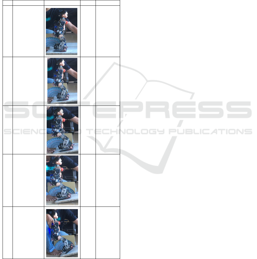
4.3 Balancing Control using Pressure
Sensor
The next test is testing the balance of the robot.
Testing in this case is to find out whether the robot is
able to balance itself when it is in a sloping and
uneven field condition with information from the
pressure center or Center Of Pressure (COP). In this
test the test was carried out to see the robot's response
when it was in the inclined plane. When tilted the
value of Ycop will be displayed through the serial
monitor on the PC / laptop. In the previous research
the balance of the robot using the IMU sensor. The
feedback used to control the balance of the robot lies
in the hand. This is because the hand response is more
efficient to make the robot stable in walking without
interfering with walking planning in walking. But in
the Dance Robot hand movements are very varied and
are needed in beautifying the dance so that in the art
robot the feedback dance with hand control becomes
inefficient. In these conditions robotic testing is
carried out in standing in a sloping condition. Table 3
shows the results of testing the condition of the robot
when in the inclined plane with no balance and with
the balance of the hand when tilted towards the front
and back.
Table 3: Test Results Robots Without Balancing Control.
No Slope Angle Notes
1 0 Not Falling
2 5 Not Falling
3 10 Falling
4 15 Falling
5 20 Falling
From the results of these tests, it can be seen that in
conditions without balance, the robot can only stand
up to a slope of 5 degrees. From these data, changes
in the robot's response were made using the foot
Balancing Control System for Humanoid Robot using Pressure Sensor
1363
response. After that, testing the slope of the robot is
carried out with a balance of information on the
position of the center of pressure. The next test is by
testing the inclined plane, but it is done by using the
Control with robotic pressure center information.
Table 4 shows the results of testing the robot's
response when tilted with a balance from the
information position of the robot pressure center.
Table 4: Test Results Robot with Balancing Control.
No Slope Angle Robot Condition Ycop Notes
1 0
1 Not Falling
2 5
-14 Not Falling
3 10
-29 Not Falling
4 15
-42 Not Falling
5 20
-56 Falling
5 CONCLUSIONS
From testing canter of pressure on the right and left
foot with the result an average error of 0.13% using
FSR sensor can be declared to work well. The use of
the FSR Sensor to measure any pressure on the sole
of the robot's foot can be done and can be
implemented for balance data the robot beside of
using IMU Sensor. With balancing control system
using PID control method, robot can stand and
adaptation by itself during difference slope from the
plane until 15 degrees. Result from this research can
be another sensor option for the balance of humanoid
robots. It is hoped that the development of humanoid
robots can be combined with other inertial sensors to
become a better balancing control system.
ACKNOWLEDGEMENTS
If any, should be placed before the references section
without numbering.
REFERENCES
D. P. Riananda, A. Wijayanto, A.H. Alasiry, A.S.
Khalilullah (2018). Walking Trajectory Optimization
Algorithm for Robot Humanoid on Synthetic Grass.
EMITTER International Journal of Engineering
Technology 6 (1), 35-61.
Al-Shuka, H., Corves, B., Zhu, W., & Vanderborght, B.
(2016). Multi-level control of zero-moment point-based
humanoid biped robots: A review, Robotica, 34(11),
2440-2466. Cambridge University Press 2015
M. Zafar and H. I. Christensen (2016). Whole body control
of a wheeled inverted pendulum humanoid. IEEE-RAS
16th International Conference on Humanoid Robots
(Humanoids), Cancun, pp. 89-94.
A. A. Saputra, I. A. Sulistijono, A. S. Khalilullah, T. Takeda
and N. Kubota (2014). Combining pose control and
angular velocity control for motion balance of
humanoid robot soccer EROS. IEEE Symposium on
Robotic Intelligence in Informationally Structured
Space (RiiSS), Orlando, FL, pp. 1-6.
A. H. Alasiry, N. F. Satria and A. Sugiarto (2018). Balance
Control of Humanoid Dancing Robot ERISA while
Walking on Sloped Surface using PID. International
Seminar on Research of Information Technology and
Intelligent Systems (ISRITI), Yogyakarta, Indonesia,
pp. 577-581, doi: 10.1109/ISRITI.2018.8864447.
iCAST-ES 2021 - International Conference on Applied Science and Technology on Engineering Science
1364
